P H Y S I C S Copyright © 2018 The Authors, some rights reserved; exclusive licensee American Association for the Advancement of Science. No claim to original U.S. Government Works. Distributed under a Creative Commons Attribution NonCommercial License 4.0 (CC BY-NC).
Near-field strong coupling of single quantum dots
Heiko Groß,1Joachim M. Hamm,2Tommaso Tufarelli,2* Ortwin Hess,2†Bert Hecht1†
Strong coupling and the resultant mixing of light and matter states is an important asset for future quantum technologies. We demonstrate deterministic room temperature strong coupling of a mesoscopic colloidal quan-tum dot to a plasmonic nanoresonator at the apex of a scanning probe. Enormous Rabi splittings of up to 110 meV are accomplished by nanometer-precise positioning of the quantum dot with respect to the nanoresonator probe. We find that, in addition to a small mode volume of the nanoresonator, collective coherent coupling of quantum dot band-edge states and near-field proximity interaction are vital ingredients for the realization of near-field strong coupling of mesoscopic quantum dots. The broadband nature of the interaction paves the road toward ultrafast coherent manipulation of the coupled quantum dot-plasmon system under ambient conditions.
INTRODUCTION
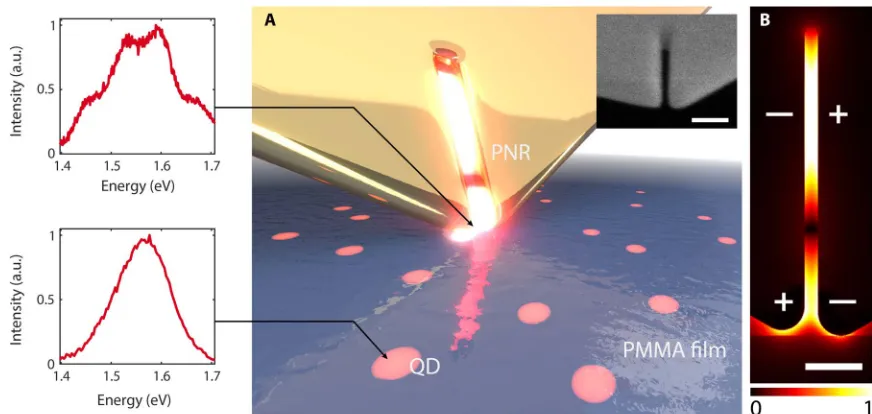
Strong coupling (SC) of light and matter occurs if photons stored in a cavity with mode volumeVand quality factorQare repeatedly ex-changed with electronic excitations in matter. Under these conditions, light and matter give up their separate identities and new dressed states arise, which modulate the response of the system to external stimuli de-pending on the coupling strength and photon number. To achieve SC withnemitters, the interaction rategºpffiffiffiffiffiffiffiffiffin=Vneeds to exceed the cav-ity loss ratekº1/Qand the total emitter decay rateG. Yet, SC of only a single quantum emitter to a cavity mode is of particular interest because it results in single-photon nonlinearities for quantum gates (1) and ef-ficient single-photon sources (2). In high-Qcavities, this single-emitter SC has successfully been achieved, but only at cryogenic temperatures by coupling to single-emitter zero-phonon lines (3). Conversely, by re-ducing the mode volume in plasmonic resonators and by using large numbers of emitters, SC has also been achieved at room temperature (4–9), with recent experiments reaching the single-emitter limit (10,11). Here, we demonstrate tunable SC of single colloidal semiconductor quantum dots (QDs) and a broadband plasmonic nanoresonator (PNR) at room temperature. We use a slit-like PNR fabricated at a corner of a single-crystal gold flake (fig. S1), which serves as a scanning probe (Fig. 1A). Nanometer-precise raster scanning of these probes across a sample containing single colloidal QDs allows us to precisely tune and optimize the coupling strength and to measure the corresponding intriguing changes in the fluorescence spectrum due to SC (see Fig. 1A, insets).
According to the standard theory (12), the coupling rate of a point dipole emitter and a resonator mode is defined as
gðrÞ ¼m⋅E0ðrÞ=ℏ ð1Þ
wheremis the dipole moment of the emitter andE0(r) is the mode’s vacuum field, evaluated at the emitter positionr. In Eq. 1, the mode field and the emitter’s dipole moment are assumed to be inde-pendent properties of the cavity and the emitter, respectively. This assumption is perfectly valid for systems whose characteristic length
scales are larger or comparable to the photon wavelength. However, coupling of emitters to subwavelength localized plasmonic modes, known to enhance local electromagnetic fields at optical frequencies, inevitably entails close proximity of the emitter and resonator, which will lead to near-field effects such as image and influential charging due to Coulomb interactions (near-field proximity effect). As we will show in this work, Eq. 1 is therefore expected to underestimate the actual value ofgbut is still useful to guide the experiments.
The PNR’s particular shape was chosen for three reasons. (i) The resonant modes (see instantaneous charge distribution in Fig. 1B) have multipolar character, giving rise to reduced radiative losses with Qfactors as high as 30 (fig. S4), corresponding to comparatively low decay rates of 13 THz (13). Photons emitted to the far field by the slit resonator are strongly polarized (13) along the transverse axis of the resonator. (ii) A gap mode is sustained even for very narrow gaps down to the subnanometer range (14). Because the gap width is reduced, the mode energy is increasingly localized in the dielectric gap rather than in the gold (15), whereas radiation is further suppressed. (iii) The open end of the slit resonator is an ideal location to position an emitter because here the modal field distribution leaks out of the enclosed space of the slit resonator in ways similar to scanning near-field optical microscopy probes.
RESULTS
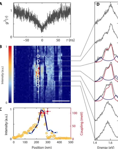
We apply scanning probe technology to reliably and repeatedly position single QDs with nanometer precision beneath the slit opening (16). The coupling strength of a single quantum emitter to the resonator mode can therefore be varied dynamically and reversibly by changing the po-sition of the QD with respect to the PNR. We investigate colloidal CdSeTe/ZnS nanocrystals (QDot800, Thermo Fisher Scientific Inc.) with an average emission wavelength of 800 nm dispersed on a glass coverslip and embedded in a 10-nm-thin polymethyl methacrylate (PMMA) film (Supplementary Materials). Before coupling with a PNR, we verify that the isolated emitter is a single QD by confirming that the intensity autocorrelationg2(0) is below 0.5 (Fig. 2A). Figure 2B shows a photoluminescence (PL) map obtained by scanning a single QD beneath the PNR (fig. S14) within the focus of an inverted confocal microscope (lexc= 532 nm, excitation rateL= 10 MHz; fig. S3). Because
of a slight asymmetry in the position of the slit at the probe apex or possibly a small overall tilt of the probe, only one of the tines contributes significantly to the near-field intensity enhancement, resulting in a single localized enhancement spot. The telegraphic on/off behavior, as 1
Nano-Optics and Biophotonics Group, Experimentelle Physik 5 and Röntgen Research Center for Complex Material Systems, Universität Würzburg, Am Hubland, 97074 Würzburg, Germany.2The Blackett Laboratory, Department of Physics, Imperial
College London, London SW7 2AZ, UK.
*Present address: School of Mathematical Sciences, University of Nottingham, Nottingham NG7 2RD, UK.
†Corresponding author. Email: hecht@physik.uni-wuerzburg.de (B.H.); o.hess@imperial. ac.uk (O.H.)
S C I E N C E A D V A N C E S |
R E S E A R C H A R T I C L E
on March 6, 2018
http://advances.sciencemag.org/
the scan image is recorded line by line, provides further proof for the coupling of a single QD to the PNR (17,18). The broad diffraction-limited background in Fig. 2B is dominated by an intense 60-nm-wide peak. Figure 2C shows a vertical line cut of the PL map (yellow open circles) at the peak position indicated by two arrows. Because the exci-tation rate (10 MHz in this measurement) is below the saturation rate, the increase of the absorption cross section in the presence of the probe dominates the fluorescence enhancement and the shape of the line cut (fig. S12). We investigate the coupling with the PNR and the occurrence of SC by recording emission spectra as a function of the QD’s position with respect to the PNR, as indicated by the white circles in Fig. 2B. To ensure that the drift of the tip between the recording of the PL map and the spectra is negligible during this process, we compare the intensity of the integrated spectra (blue line) with the spectrally integrated PL map and observe good agreement. Next, we analyze the particular shapes of the spectra because they reveal the coupling between the electronic states of the QD and the PNR. Figure 2D displays the recorded spectra, which have been normalized for better comparison. For large QD probe separations, the shape of the spectrum matches the fluorescence spec-trum of a weakly coupled system. With increasing coupling strength, we observe pronounced changes of the emission spectrum of the coupled system. At the position of maximum resonant field strength, we discern a transition into the SC regime, but contrary to the characteristic two-peak splitting of conventional SC, an unexpected appearance of four peaks is observed. When the PNR is moved further away from the QD, the coupling strength decreases and the spectrum transforms back to that of a weakly coupled QD, signifying a truly reversible and con-trollable process.
We now show that the appearance of four peaks can be attributed to the charged and neutral QD states, which both couple strongly with the PNR, therefore contributing a Rabi doublet each. On the first glance, it is tempting to interpret the two doublets appearing jointly as signatures of the first and second rung of the Jaynes-Cummings ladder. However, because the interplay of excitation, coupling, and loss rates in our
exper-iment are prohibitive for populating higher photon states, the two doublets must relate to the SC of the PNR mode to different QD states. This is possible because, in contrast to high-Qresonators with very nar-row resonances, a“broadband”PNR with a 78-meV bandwidth can co-herently cover multiple exciton resonances, giving rise to simultaneous probing of both QD charge states (19). The QD has a diameter of about 8 nm, leading to a small energy separation of less than 20 meV between the neutral exciton and the charged exciton (20). Charge carrier trapping of hot electrons upon incoherent excitation is a common process in QDs, leaving behind a positively charged nanocrystal core (21–25). Typically, however, this charged exciton (trion) is optically dark due to highly efficient nonradiative Auger decay (18,26). Yet, here, SC via plasmons provides a radiative decay channel, which is significantly faster than the Auger processes, rendering the charged trion state optically active (27). Consequently, the QD states in-volved in the spectral response are the neutral and positively charged QD (trion) states (17). Because in general an additional charge in the QD causes increased electron-hole interaction leading to a reduced wave function overlap (28), we assign the neutral state to the outer Rabi doublet and the charged state to the inner one. The relative Rabi splitting of both states is a direct measure of the relative magnitude of the involved total transition dipole moments. We also note that re-cent dark-field spectroscopy experiments on QDs in bowtie nanoan-tenna gaps did not show four peaks (11). We ascribe this behavior to the resonant excitation via the antenna and the resulting absence of hot electrons as the main source of charging events at low excitation rates.
[image:2.594.77.513.54.261.2]A simple coupled oscillator model is sufficient to predict plasmon-exciton hybridization on a semiclassical level but does not allow the cal-culation of emission spectra without an (artificial) addition of stochastic noise terms. Thus, to explain the measured spectra, we formulate a quantum optical model based on the Lindblad master equation. Our model describes the interaction of a quantum emitter represented as a five-level quantum system with a broadband cavity to capture
Fig. 1. SC via precise nanopositioning of a resonator probe.(A) Illustration of the PNR probe interacting with QDs embedded in a polymer film. Left panel: The spectrum of a QD changes significantly when coupled to the slit-like PNR at the tip apex. Inset: SEM image of a nanoresonator at the apex of a probe tip. Scale bar, 100 nm. a.u., arbitrary unit. (B) Map of the electric field distribution of the resonator mode used in the experiment. The slightly different lengths of the two tines account for fabrication imperfections. The + and−signs indicate the instantaneous charge distribution highlighting the mode’s weakly radiative quadrupolar character. Scale bar, 50 nm.
on March 6, 2018
http://advances.sciencemag.org/
the essential transitions of neutral and charged QD states (two levels each) and a multiple charged state (single level; fig. S15). The evolu-tion of the density matrixris given by
r:¼ i½HI;r þ 1 2
∑
kð2LkrL†kL†kLkrrL†kLkÞ
where the HamiltonianHIdescribes the coherent interaction of the cavity with two transitions in the QD (see the Supplementary Materials for details). With the jump operatorsLk, we take into account all in-coherent processes including pumping, dephasing, radiative and non-radiative decay, and population transfer between neutral and charged QD states. Because most of the photons emitted from the strongly coupled system reach the far field via the cavity, the emission spectra are calculated via
SðwÞº2Re
∫
∞0a†ðtÞað0Þeiwtdt
whereais the annihilation operator of the cavity mode. The calculated spectra are shown in Fig. 2D (solid lines), in direct comparison with
measured data, and reveal a coupling strength of 110 and 44 meV for the neutral (gn) and charged (gc) exciton, respectively, resulting in a cou-pling strength ratiogc/gnof 0.4.
The coupling strengthgc, extracted from a best fit to the
experimen-tal spectra, is plotted for each QD-PNR separation in Fig. 2C (red dots). We observe that the three spectra with the highest coupling strength are recorded close to the QD emission peak. The spectrum with the highest coupling strength exhibits a comparably small emission intensity, an effect caused by the spatial displacement of the near-field intensity max-ima of the nonresonant excitation field (532 nm) and the resonant mode field (800 nm) at the tip apex of the PNR (fig. S8).
The model correctly describes the experimental data in the SC re-gime, where coherent light-matter quantum dynamics are dominant and allow the reproduction of the shape and intensities of all four peaks. However, when extended to the weak coupling regime, it tends to underestimate the width of the spectral features. This is not surprising because modeling a QD as a five-level quantum emitter will always sim-plify several intrinsic QD dynamical degrees of freedom, which are re-sponsible for its broad emission spectrum but which do not significantly contribute to SC. Using a well-established pure dephasing model with a dephasing rate ofgd= 160 fs for the QD, our quantum optical master
equation accurately reproduces the spectra in the SC regime, where coherent coupling dominates over phononic processes. In the weak coupling regime, the emission properties of the QD are heavily affected by phonons in a way that may not be accurately described by a pure dephasing model (29). Furthermore, the spectral width can also be influenced in the experiment due to the reduced charge fluctuations induced by the presence of the metallic probe as a function of dis-tance between QD and PNR (30,31). We have experimentally veri-fied the effect of tip-induced spectral narrowing independently using an unstructured gold tip (fig. S10).
Uncoupled CdSeTe/ZnS nanocrystals display a blue shift for higher excitation intensities as the contribution of biexciton emission increases (32). This spectral shift also occurs for the QDs used in the present experiment and is shown in Fig. 3A for three different excitation inten-sities (fig. S9). Under SC conditions, this blue shift causes an intensity-dependent detuning of the QD with respect to the PNR. Figure 3B shows a series of normalized SC spectra for increasing excitation rate (bottom to top; see fig. S17 for reversibility). The increasing detuning to higher energies causes characteristic changes of the amplitudes and shifts of the Rabi peaks. The quantum model (solid line) reproduces this behavior by changing the individual resonance energy of the neutral and charged states while keeping the cavity resonance fixed. Note that we observe a saturation in fluorescence intensity due to multicharged QD states (fig. S20). In Fig. 3C, we plot the peak energies for increasing pump rate (blue shift) for several QDs showing different tuning ranges. The red markers include the peak positions of the spectra in Fig. 3B. For comparison, we show the peak energies of the neutral and charged state (black and gray solid line, respectively) extracted from the quantum model for varying detunings (dashed line) with respect to the PNR (dotted line), demonstrating spectral anti-crossing of both QD states with the PNR spectrum—a well-known manifestation of SC.
DISCUSSION
[image:3.594.39.288.53.367.2]To understand why we observe SC with QDs, which are normally not bestowed with the largest dipole matrix elements, we have to focus in more detail on the coupling mechanism between colloidal QDs and the PNR at the scanning probe apex. The coupling strength, Eq. 1, depends
Fig. 2. Separation-dependent coupling strength.(A) Second-order auto-correlation of the photons emitted by a single QD in the absence of the probe. (B) PL map of the QD scanned beneath a PNR. The white circles indicate the positions in which the spectra have been recorded. Scale bar, 100 nm. (C) Open yellow circles: Normalized line cut of the PL map in (B) (arrow). Full blue circles: Integrated spectral amplitude recorded at the positions indicated by white circles in (B). Red circles: Coupling strength (right axis) used to model the SC spectra in (D). (D) Gray lines: Normalized spectra recorded for different coupling strengths. Solid lines: Spectra obtained from the quantum optical model with contribution of neutral state (blue) and charged state (red).
S C I E N C E A D V A N C E S |
R E S E A R C H A R T I C L E
on March 6, 2018
http://advances.sciencemag.org/
on the vacuum field strength and the related effective mode volume (fig. S5), as well as the emitter’s dipole moment. Regarding the dipole moment, colloidal QDs are known to exhibit a fine-structure splitting due to their crystal lattice anisotropy and electron-hole interaction, leading to eight different (partially degenerate) states near the band edge (28), with the lowest state usually being optically dark (Fig. 4A, top). The lowest optically active statefbrightis thermally populated and determines
the optical emission properties such as the resonance energy and excited state lifetime of uncoupled QDs (33). The measured lifetime of (58 ± 4) ns corresponds, on the basis of the Weisskopf-Wigner approximation, to an electric dipole moment of 5 Debye (Supplementary Text). However, because the plasmon resonance widthDwis larger than the total fine-structure splittingD, it can interact with all band-edge statesfk
simulta-neously (Fig. 4A, bottom), some of which are also reported to exhibit larger transition oscillator strengths thanfbright(34,35). As shown in the
Fig. 2D measurement, the slight asymmetry of the spectra in Fig. 2D is attributed to a blue shift of the QD emission when entering the SC regime. This indicates the transition from pure emission of the lowest optically active state at the band edge to the blue-shifted effective con-tribution of all available statesfk. In addition, the near-field intensity
close to the tip shows a significant gradient of one order of magnitude over length scales of the QD dimensions. In combination with a non-spherical QD shape, the plasmonic mode is therefore expected to also couple to multipolar transitions (36–38). A quantum optical model, which incorporates a nondegenerate multilevel emitter strongly coupled with a broadband resonator (fig. S19), explains and quantifies this boost of coupling strength due to collective coupling to band-edge states. The importance of the fine structure in cavity quantum electrodynamics (cQED) experiments has been recently studied in photonic crystal cav-ities (39), and the boost of the coupling constant is expected to be even more effective in plasmonic cavities due to a spectral width that is orders of magnitude larger. Our quantum model shows that the coupling strength is effectively tripled by collective coupling of eight active transi-tions at the band edge, veritably revealing the full potential of colloidal QDs as excitonic material for strong light-matter interaction.
In addition to the QD dipole moment, the evaluation of the vacuum field strength also requires a thorough study. In the dipole approxima-tion, the coupling rate as described in Eq. 1 is proportional to the vac-uum field strength, which depends on the mode volumeVeff(r) via
E0ðrÞ ¼
ffiffiffiffiffiffiffiffiffiffiffiffiffiffi ħw
2e0VeffðrÞ
q
, whereris the position of the point-like emitter.
We performed finite-difference time-domain simulations based on quasi-normal modes, taking into account the local field factor (40) by including a spherical semiconductor particle mimicking the QD inter-action with the PNR. The resulting coupling strength map (fig. S5) shows large variations ofg(r) especially in close proximity to and also inside the semiconductor particle. This observation demonstrates that because of the finitely sized QD, determination of the coupling rate in the dipole approximation via Eq. 1 is no longer applicable. It also strengthens the assumption that multipolar transitions and therefore all fine-structure statesfkare optically accessible. The occurrence of a
[image:4.594.115.480.51.246.2]hot spot between the semiconductor particle and the gold already indicates the importance of short-ranged influential confinement effects (41) even in the absence of a QD exciton. We therefore argue that because of a strong, distance-dependent polarization of the metal surface for resonant interaction, the resonator and the (mesoscopic) QD can no longer be treated as independent entities if the emitter is in close proximity to the PNR (Fig. 4B). This is not only important in experiments such as ours but also of general significance. Let us thus demonstrate the role of near-field proximity-enhanced coupling for a system of two coupled gold nanorods exhibiting classical mode splitting (fig. S6). We can immediately see that for larger nanorod separations, the coupling strengths can be determined according to Eq. 1 using the near field of an isolated nanorod. However, for smaller separations in the presence of influential charging, the coupling strength according to Eq. 1 underestimates the observed coupling strength determined via the observed mode splitting. The occurrence of this near-field proximity coupling consequently challenges the applicabil-ity of the standard dipolar SC formalism of cQED, which assumes that the mode field and the related effective mode volume can be
Fig. 3. QD detuning at high excitation rates.(A) Fluorescence spectra of uncoupled QDs. With increasing excitation rate (bottom to top), the peak intensity indicates a blue shift. (B) Spectra for increasing pump rate (gray lines, bottom to top) overlaid with calculated spectra (solid lines) for different detunings. (C) Peak positions for a range of detunings induced by different excitation rates of three different QDs. The Rabi peak positions of the neutral (charged) QD state based on the quantum model are indicated by the solid black (gray) lines. The gray dashed (dotted) line indicates the QD (PNR) resonance.
on March 6, 2018
http://advances.sciencemag.org/
determined independently and, in particular, in the absence of the emitter.
The experiments presented in this work highlight the ability of the scanning probe setup used in the present study to use a PNR to probe a larger number of different single QDs, offering an advantage in compar-ison to conventional multistep lithographic techniques (42,43). Exper-imental uncertainties regarding (time-)varying properties of quantum emitters and exact positioning do not have to be counteracted by statis-tical analysis. We find that if a particular PNR can achieve SC (3 of 30 PNR probes), then the characteristic spectral changes can be measured for most of the QDs. Assuredly, the SC spectra of different single QDs obtained with the same PNR exhibit a qualitatively similar behavior. Nevertheless, variations in coupling strength and detuning parameters are observed, owing to structural differences of the colloidal QDs as well as to their orientation with respect to the electric field polarization at the apex of the PNR (fig. S18). For most of the PNR probes, weak coupling was observed, which is characterized by the well-known Purcell en-hancement (fig. S11). These findings underline that our system is capa-ble of performing a characterization of single QDs via SC spectroscopy under ambient conditions.
CONCLUSION
We have demonstrated SC of a scanning PNR probe to a single semi-conductor QD under ambient conditions. This allows us to deliberately undergo the transition into (and out of) the SC regime for any chosen QD in range. A hierarchy of quantum models accurately predicts the SC dynamics and the resulting spectral response. Detailed analysis of the plasmonic field and the electronic structure of the semiconductor
nano-crystal challenges the current understanding of SC. In particular, we identify collective coupling of a band-edge multiplet of states as a novel formula to achieve single-emitter SC. We reveal that near-field proxim-ity coupling requires a reconsideration of the direct applicabilproxim-ity of stan-dard SC theory in dipole approximation to PNRs.
Advances in nanofabrication, such as helium ion milling, will help to further reduce the width of the nanoslits well below 10 nm, which may lead to the development of polaritonic devices, and to eventually facil-itate entering the realm of ultrastrong coupling. The direct applicability of the presented methodology to any zero-dimensional (0D), 1D, and 2D quantum system promises a vast impact on the investigation of light-matter interaction on the nanometer scale.
MATERIALS AND METHODS
For our measurements, we customized commercially available contact mode cantilevers by placing hexagonal single-crystalline gold flakes at the end of the cantilever. We then used focused ion beam (FIB) lithog-raphy to fabricate a PNR at one of the corners of the hexagon. This modified corner serves as the probe tip, which is used to raster scan across a surface covered with CdSeTe/ZnS QDs embedded in a thin PMMA film.
Cantilever preparation
In the first process step, the tip at the end of a contact mode cantilever (doped silicon and no reflective coating, Contact-G-50, NanoAndMore GmbH; see fig. S1A) is cut off via FIB milling (fig. S1B). Single-crystalline gold flakes are synthesized in solution based on a recipe by Guoet al. (44) and directly grown on a glass substrate (45). A flake (typical thickness, 60 nm) is picked up with a needle attached to a micromanipulator and placed at the end of the tipless cantilever such that one corner juts out 5 to 10mm beyond the cantilever (fig. S1C). Next, the PNR is fabricated at the protruding corner of the flake via FIB lithography with gallium ions by performing a single line cut (fig. S1D). Consistent results can be achieved for different flake thicknesses by adjusting the ion dose. We did not observe any issues regarding gallium ion implantation because it mainly (if at all) concerns the substrate (46). Because in our case the etching takes place on a free-standing gold flake, we assume negligible gallium contamination. Subsequent large-area ion irradiation of the protruding gold flake close to the cantilever induces strain and causes the gold flake to bend down (fig. S1, E and F). This ensures that the resonator becomes the foremost part of the probe that touches the sample first (fig. S1G).
[image:5.594.51.275.54.277.2]Figure S2A shows a scanning electron microscopy (SEM) image of the modified contact mode cantilever with a gold flake mounted on the back side before flake bending. The PNR location is marked by a circle. The inset (fig. S2B) displays a variety of PNRs fabricated for different scanning probes. Because the flake thickness and edge geometry are dif-ferent for each flake, the PNR gap width and the overall geometry can vary. By adjusting the length of the cut, we can tune the cavity to any desired resonance wavelength. FIB milling a PNR on a free-standing gold sheet creates symmetrically rounded edges inside the resonator si-milar to the gap geometry observed in self-assembled gold dimers. These types of structures show excellent field confinement and small mode volumes (14). In comparison, top-down structuring on substrates always leads to asymmetric structures, which are narrow at the top and broad close to the substrate. Single-crystal gold flake features excellent mechanical elasticity and durability. In combination with the soft polymer-coated sample, PNR probes can be scanned in contact mode force
Fig. 4. Enhanced coupling of QD and PNRs due to collective coupling of band-edge states and near-field proximity effect.(A) Diagram of energy levels of a CdSeTe/ZnS nanocrystal weakly coupled (top) and strongly coupled (bottom) to a resonator. Fine-structure splitting into bright (black lines) and dark states (gray lines). Incoherent excitation from the ground state G into a pump state P and subsequent relaxation to the band edge E. (B) Top: Sketch of the near-field distribution at the apex of the resonator (pure mode). Bottom: Strongly coupled mesoscopic emitter influences the pure mode field via near-field proximity inter-action (influential and image charging).
S C I E N C E A D V A N C E S |
R E S E A R C H A R T I C L E
on March 6, 2018
http://advances.sciencemag.org/
feedback without signs of wear. Probes can be stored under ambient conditions and reused for further experiments.
QD substrate preparation for SC experiments
We spin-coated an aqueous solution (8 nM) of CdSeTe/ZnS QDs (QDot800 ITK Q21571MP, Thermo Fisher Scientific Inc.) on cleaned microscope coverslips (#1, Gerhard Menzel GmbH). Further spin coating of a 0.4% PMMA solution preserves the nanocrystal in a thin air-dried PMMA matrix to inhibit shell oxidation and to protect the QDs from being picked up and pushed away by the probe. We mea-sured the height of the PMMA layer using atomic force microscopy (AFM) by scratching locally with a razor blade. The average PMMA thickness was measured to be 12 nm and completely covers the em-bedded CdSeTe/ZnS QDs. At the same time, a QD diameter of about 8 to 11 nm ensures a minimum distance between the PNR and the emitter. We found the QDs to be highly stable over a period of at least 3 months. Comparison with a fresh sample did not show any dif-ference of the optical performance. SEM images of the QDs (for SEM purposes prepared on a conducting substrate) are displayed in Fig. S2C and confirm the size and shape distribution observed in pre-vious transmission electron microscopy studies (47,48).
Optical setup
Figure S3 sketches the optical setup. We used a continuous-wave laser diode (frequency-doubled Nd:YAG) with an emission wavelength of 532 nm to illuminate the sample via a beam splitter (ratio, 50:50) and a high numerical aperture (NA) objective (Plan APO TIRF 100×, NA 1.45, Nikon). The AFM (Bioscope, Bruker) is mounted on a customized stage on top of the sample holder stage. A 720-nm low-pass (LP) filter is used to filter the fluorescence light and to suppress the light of the broad AFM deflection laser (685 nm). To further reduce any residual light of the excitation laser, we used an additional 540-nm LP filter. The fluo-rescence light passes a beam splitter (ratio, 90:10), in which 90% of the transmitted light is focused via a lens (f= 300 mm) on the entrance slit of a spectrometer (Acton SpectraPro 2300i, 300 lines/mm), where it is detected by a Peltier-cooled charge-coupled device camera (Andor DU401A BR-DD). The remaining 10% of the light is directed to a po-larizing beam splitter, resulting into two orthogonally polarized beam paths, which are detected individually by two single-photon counting modules (SPCM-AQR, Perkin and Elmer). Exchanging the polarizing beam splitter with a nonpolarizing beam splitter allows us to perform Hanbury-Brown and Twiss autocorrelation measurements.
SUPPLEMENTARY MATERIALS
Supplementary material for this article is available at http://advances.sciencemag.org/cgi/ content/full/4/3/eaar4906/DC1
Supplementary Text
fig. S1. Scanning probe fabrication. fig. S2. SEM characterization. fig. S3. Schematic of the optical setup.
fig. S4. Simulated mode profiles and far-field spectra of PNRs for different gap widths and slit lengths between 80 and 440 nm.
fig. S5. Calculating the coupling strength. fig. S6. Near-field proximity coupling. fig. S7. Purcell factor of PNR.
fig. S8. Emission and excitation near-field distribution. fig. S9. QD resonance shift for high excitation rates. fig. S10. Coupling of a QD to an unstructured gold tip. fig. S11. Weak coupling PNR scanning probe.
fig. S12. Difference between excitation and emission enhancement.
fig. S13. Calculated fluorescence peaks for different excitation rates for an emitter scanned through a Gaussian field profile with a Purcell factor reaching up to 1000.
fig. S14. Cavity characterization. fig. S15. Five-level diagram of the QD.
fig. S16. Decomposing the emission of a strongly coupled QD. fig. S17. Reversible blue shift for increased excitation rates during SC. fig. S18. Collection of spectra of five different QDs in SC with the PNR. fig. S19. Collective coupling of a multilevel emitter with a resonant cavity. fig. S20. Saturation of the strongly coupled system.
References (49–99)
REFERENCES AND NOTES
1. A. Reiserer, N. Kalb, G. Rempe, S. Ritter, A quantum gate between a flying optical photon and a single trapped atom.Nature508, 237–240 (2014).
2. Y.-M. He, Y. He, Y.-J. Wei, D. Wu, M. Atatüre, C. Schneider, S. Höfling, M. Kamp, C.-Y. Lu, J.-W. Pan, On-demand semiconductor single-photon source with near-unity indistinguishability.Nat Nanotechnol.8, 213–217 (2013).
3. J. P. Reithmaier, G. Sek, A. Löffler, C. Hofmann, S. Kuhn, S. Reitzenstein, L. V. Keldysh, V. D. Kulakovskii, T. L. Reinecke, A. Forchel, Strong coupling in a single quantum dot–semiconductor microcavity system.Nature432, 197–200 (2004).
4. A. E. Schlather, N. Large, A. S. Urban, P. Nordlander, N. J. Halas, Near-field mediated plexcitonic coupling and giant Rabi splitting in individual metallic dimers.Nano Lett.13, 3281–3286 (2013).
5. Y. Sugawara, T. A. Kelf, J. J. Baumberg, M. E. Abdelsalam, P. N. Bartlett, Strong coupling between localized plasmons and organic excitons in metal nanovoids.Phys. Rev. Lett. 97, 266808 (2006).
6. G. Zengin, M. Wersäll, S. Nilsson, T. J. Antosiewicz, M. Käll, T. Shegai, Realizing strong light-matter interactions between single-nanoparticle plasmons and molecular excitons at ambient conditions.Phys. Rev. Lett.114, 157401 (2015).
7. G. Zengin, G. Johansson, P. Johansson, T. J. Antosiewicz, M. Käll, T. Shegai, Approaching the strong coupling limit in single plasmonic nanorods interacting with J-aggregates.Sci. Rep.3, 3074 (2013).
8. M. Wersäll, J. Cuadra, T. J. Antosiewicz, S. Balci, T. Shegai, Observation of mode splitting in photoluminescence of individual plasmonic nanoparticles strongly coupled to molecular excitons.Nano Lett.17, 551–558 (2017).
9. M.-E. Kleemann, R. Chikkaraddy, E. M. Alexeev, D. Kos, C. Carnegie, W. Deacon, A. C. de Pury, C. Große, B. de Nijs, J. Mertens, A. I. Tartakovskii, J. J. Baumberg, Strong-coupling of WSe2in ultra-compact plasmonic nanocavities at room temperature.
Nat. Commun.8, 1296 (2017).
10. R. Chikkaraddy, B. de Nijs, F. Benz, S. J. Barrow, O. A. Scherman, E. Rosta, A. Demetriadou, P. Fox, O. Hess, J. J. Baumberg, Single-molecule strong coupling at room temperature in plasmonic nanocavities.Nature535, 127–130 (2016).
11. K. Santhosh, O. Bitton, L. Chuntonov, G. Haran, Vacuum Rabi splitting in a plasmonic cavity at the single quantum emitter limit.Nat Commun.7, ncomms11823 (2016). 12. P. Törmä, W. L. Barnes, Strong coupling between surface plasmon polaritons and
emitters: A review.Rep. Prog. Phys.78, 013901 (2015).
13. I. M. Hancu, A. G. Curto, M. Castro-López, M. Kuttge, N. F. van Hulst, Multipolar interference for directed light emission.Nano Lett.14, 166–171 (2013).
14. J. Kern, S. Großmann, N. V. Tarakina, T. Häckel, M. Emmerling, M. Kamp, J.-S. Huang, P. Biagioni, J. C. Prangsma, B. Hecht, Atomic-scale confinement of resonant optical fields.Nano Lett.12, 5504–5509 (2012).
15. A. Chandran, E. S. Barnard, J. S. White, M. L. Brongersma, Metal-dielectric-metal surface plasmon-polariton resonators.Phys. Rev. B85, 085416 (2012).
16. J. N. Farahani, D. W. Pohl, H.-J. Eisler, B. Hecht, Single quantum dot coupled to a scanning optical antenna: A tunable superemitter.Phys. Rev. Lett.95, 017402 (2005).
17. M. Nirmal, B. O. Dabbousi, M. G. Bawendi, J. J. Macklin, J. K. Trautman, T. D. Harris, L. E. Brus, Fluorescence intermittency in single cadmium selenide nanocrystals.Nature 383, 802–804 (1996).
18. A. L. Efros, M. Rosen, Random telegraph signal in the photoluminescence intensity of a single quantum dot.Phys. Rev. Lett.78, 1110–1113 (1997).
19. M. Winger, A. Badolato, K. J. Hennessy, E. L. Hu, A. Imamoğlu, Quantum dot spectroscopy using cavity quantum electrodynamics.Phys. Rev. Lett.101, 226808
(2008).
20. D. Oron, M. Kazes, I. Shweky, U. Banin, Multiexciton spectroscopy of semiconductor nanocrystals under quasi-continuous-wave optical pumping.Phys. Rev. B.74, 115333 (2006).
21. K. L. Knappenberger Jr., D. B. Wong, Y. E. Romanyuk, S. R. Leone, Excitation wavelength dependence of fluorescence intermittency in CdSe/ZnS Core/Shell quantum dots.
Nano Lett.7, 3869–3874 (2007).
on March 6, 2018
http://advances.sciencemag.org/
22. K. L. Knappenberger, D. B. Wong, W. Xu, A. M. Schwartzberg, A. Wolcott, J. Z. Zhang, S. R. Leone, Excitation-wavelength dependence of fluorescence intermittency in CdSe nanorods.ACS Nano2, 2143–2153 (2008).
23. L. A. Padilha, I. Robel, D. C. Lee, P. Nagpal, J. M. Pietryga, V. I. Klimov, Spectral dependence of nanocrystal photoionization probability: The role of hot-carrier transfer.ACS Nano5, 5045–5055 (2011).
24. J. A. McGuire, M. Sykora, I. Robel, L. A. Padilha, J. Joo, J. M. Pietryga, V. I. Klimov, Spectroscopic signatures of photocharging due to hot-carrier transfer in solutions of semiconductor nanocrystals under low-intensity ultraviolet excitation.ACS Nano4, 6087–6097 (2010).
25. C. Galland, Y. Ghosh, A. Steinbrück, M. Sykora, J. A. Hollingsworth, V. I. Klimov, H. Htoon, Two types of luminescence blinking revealed by spectroelectrochemistry of single quantum dots.Nature479, 203–207 (2011).
26. V. I. Klimov, A. A. Mikhailovsky, D. W. McBranch, C. A. Leatherdale, M. G. Bawendi, Quantization of multiparticle auger rates in semiconductor quantum dots.Science287, 1011–1013 (2000).
27. K. T. Shimizu, W. K. Woo, B. R. Fisher, H. J. Eisler, M. G. Bawendi, Surface-enhanced emission from single semiconductor nanocrystals.Phys. Rev. Lett.89, 117401 (2002).
28. A. L. Efros, M. Rosen, M. Kuno, M. Nirmal, D. J. Norris, M. Bawendi, Band-edge exciton in quantum dots of semiconductors with a degenerate valence band: Dark and bright exciton states.Phys. Rev. B54, 4843–4856 (1996).
29. D. P. S. McCutcheon, A. Nazir, Model of the optical emission of a driven semiconductor quantum dot: Phonon-enhanced coherent scattering and off-resonant sideband narrowing.Phys. Rev. Lett.110, 217401 (2013).
30. K. Wilma, A. Issac, Z. Chen, F. Würthner, R. Hildner, J. Köhler, Tracing single electrons in a disordered polymer film at room temperature.J. Phys. Chem. Lett.7, 1478–1483 (2016).
31. J.-M. Segura, G. Zumofen, A. Renn, B. Hecht, U. P. Wild, Tip-induced spectral dynamics of single molecules.Chem. Phys. Lett.340, 77–82 (2001).
32. A. Avidan, D. Oron, Large blue shift of the biexciton state in tellurium doped CdSe colloidal quantum dots.Nano Lett.8, 2384–2387 (2008).
33. C. de Mello Donegá, M. Bode, A. Meijerink, Size- and temperature-dependence of exciton lifetimes in CdSe quantum dots.Phys. Rev. B.74, 085320 (2006).
34. C. de Mello Donegá, R. Koole, Size dependence of the spontaneous emission rate and absorption cross section of CdSe and CdTe quantum dots.J. Phys. Chem. C113, 6511–6520 (2009).
35. K. Gong, Y. Zeng, D. F. Kelley, Extinction coefficients, oscillator strengths, and radiative lifetimes of CdSe, CdTe, and CdTe/CdSe nanocrystals.J. Phys. Chem. C117, 20268–20279 (2013).
36. A. M. Kern, O. J. F. Martin, Strong enhancement of forbidden atomic transitions using plasmonic nanostructures.Phys. Rev. A.85, 022501 (2012).
37. J. R. Zurita-Sánchez, L. Novotny, Multipolar interband absorption in a semiconductor quantum dot. I. Electric quadrupole enhancement.J. Opt. Soc. Am.19, 1355–1362 (2002).
38. M. L. Andersen, S. Stobbe, A. S. Sørensen, P. Lodahl, Strongly modified plasmon-matter interaction with mesoscopic quantum emitters.Nat. Phys.7, 215–218 (2011). 39. K. H. Madsen, T. B. Lehmann, P. Lodahl, Role of multilevel states on quantum-dot
emission in photonic-crystal cavities.Phys. Rev. B.94, 235301 (2016).
40. Z.-J. Yang, T. J. Antosiewicz, T. Shegai, Role of material loss and mode volume of plasmonic nanocavities for strong plasmon-exciton interactions.Opt. Express24, 20373–20381 (2016).
41. P. Biagioni, J.-S. Huang, B. Hecht, Nanoantennas for visible and infrared radiation.
Rep. Prog. Phys.75, 024402 (2012).
42. A. Kinkhabwala, Z. Yu, S. Fan, Y. Avlasevich, K. Müllen, W. E. Moerner, Large single-molecule fluorescence enhancements produced by a bowtie nanoantenna.
Nat. Photonics3, 654–657 (2009).
43. A. G. Curto, G. Volpe, T. H. Taminiau, M. P. Kreuzer, R. Quidant, N. F. van Hulst, Unidirectional emission of a quantum dot coupled to a nanoantenna.Science329, 930–933 (2010).
44. Z. Guo, Y. Zhang, Y. Mao, L. Huang, N. Gu, Synthesis of microsized gold nanoplates by a self-seeding method in ethanol solution.Mater. Lett.60, 3522–3525 (2006).
45. X. Wu, R. Kullock, E. Krauss, B. Hecht, Single-crystalline gold microplates grown on substrates by solution-phase synthesis.Cryst. Res. Technol.50, 595–602 (2015). 46. J.-S. Huang, V. Callegari, P. Geisler, C. Brüning, J. Kern, J. C. Prangsma, X. Wu, T. Feichtner,
J. Ziegler, P. Weinmann, M. Kamp, A. Forchel, P. Biagioni, U. Sennhauser, B. Hecht, Atomically flat single-crystalline gold nanostructures for plasmonic nanocircuitry.
Nat. Commun.1, 150 (2010).
47. M. Song, B. Wu, G. Chen, Y. Liu, X. Ci, E. Wu, H. Zeng, Photoluminescence plasmonic enhancement of single quantum dots coupled to gold microplates.J. Phys. Chem. C118, 8514–8520 (2014).
48. B. Rogez, H. Yang, E. Le Moal, S. Lévêque-Fort, E. Boer-Duchemin, F. Yao, Y.-H. Lee, Y. Zhang, K. David Wegner, N. Hildebrandt, A. Mayne, G. Dujardin, Fluorescence lifetime
and blinking of individual semiconductor nanocrystals on graphene.J. Phys. Chem. C118, 18445–18452 (2014).
49. M. Kuno, D. P. Fromm, H. F. Hamann, A. Gallagher, D. J. Nesbitt, Nonexponential“blinking” kinetics of single CdSe quantum dots: A universal power law behavior.
J. Chem. Phys.112, 3117–3120 (2000).
50. D. J. Norris, M. G. Bawendi, Measurement and assignment of the size-dependent optical spectrum in CdSe quantum dots.Phys. Rev. B53, 16338–16346 (1996).
51. G.-X. Liang, L.-L. Li, H.-Y. Liu, J.-R. Zhang, C. Burda, J.-J. Zhu, Fabrication of near-infrared-emitting CdSeTe /ZnS core/shell quantum dots and their electrogenerated
chemiluminescence.Chem. Commun.46, 2974–2976 (2010).
52. G.-X. Liang, M.-M. Gu, J.-R. Zhang, J.-J. Zhu, Preparation and bioapplication of high-quality, water-soluble, biocompatible, and near-infrared-emitting CdSeTe alloyed quantum dots.Nanotechnology20, 415103 (2009).
53. S. Kim, B. Fisher, H.-J. Eisler, M. Bawendi, Type-II quantum dots: CdTe/CdSe(core/shell) and CdSe/ZnTe(core/shell) heterostructures.J. Am. Chem. Soc.125, 11466–11467 (2003). 54. R. E. Bailey, S. Nie, Alloyed semiconductor quantum dots: Tuning the optical properties
without changing the particle size.J. Am. Chem. Soc.125, 7100–7106 (2003). 55. L. Zhang, Z. Lin, J.-W. Luo, A. Franceschetti, The birth of a type-II nanostructure: Carrier
localization and optical properties of isoelectronically doped CdSe:Te nanocrystals.
ACS Nano6, 8325–8334 (2012).
56. M. A. Hines, P. Guyot-Sionnest, Synthesis and characterization of strongly luminescing ZnS-Capped CdSe nanocrystals.J. Phys. Chem.100, 468–471 (1996).
57. O. Labeau, P. Tamarat, B. Lounis, Temperature dependence of the luminescence lifetime of single CdSe/ZnS quantum dots.Phys. Rev. Lett.90, 257404 (2003).
58. M. D. Leistikow, J. Johansen, A. J. Kettelarij, P. Lodahl, W. L. Vos, Size-dependent oscillator strength and quantum efficiency of CdSe quantum dots controlled via the local density of states.Phys. Rev. B.79, 045301 (2009).
59. S. A. Crooker, T. Barrick, J. A. Hollingsworth, V. I. Klimov, Multiple temperature regimes of radiative decay in CdSe nanocrystal quantum dots: Intrinsic limits to the dark-exciton lifetime.
Appl. Phys. Lett.82, 2793–2795 (2003).
60. C. Ciuti, G. Bastard, I. Carusotto, Quantum vacuum properties of the intersubband cavity polariton field.Phys. Rev. B72, 115303 (2005).
61. M. Nirmal, D. J. Norris, M. Kuno, M. G. Bawendi, A. L. Efros, M. Rosen, Observation of the “Dark Exciton”in CdSe quantum dots.Phys. Rev. Lett.75, 3728–3731 (1995). 62. Q. Zhao, P. A. Graf, W. B. Jones, A. Franceschetti, J. Li, L.-W. Wang, K. Kim, Shape
dependence of band-edge exciton fine structure in CdSe nanocrystals.Nano Lett.7, 3274–3280 (2007).
63. I. Moreels, G. Rainò, R. Gomes, Z. Hens, T. Stöferle, R. F. Mahrt, Band-edge exciton fine structure of small, nearly spherical colloidal CdSe/ZnS quantum dots.ACS Nano5, 8033–8039 (2011).
64. C. d. M. Donegá, Synthesis and properties of colloidal heteronanocrystals.Chem. Soc. Rev.40, 1512–1546 (2011).
65. M. Achermann, J. A. Hollingsworth, V. I. Klimov, Multiexcitons confined within a subexcitonic volume: Spectroscopic and dynamical signatures of neutral and charged biexcitons in ultrasmall semiconductor nanocrystals.Phys. Rev. B68, 245302 (2003). 66. A. F. van Driel, G. Allan, C. Delerue, P. Lodahl, W. L. Vos, D. Vanmaekelbergh,
Frequency-dependent spontaneous emission rate from CdSe and CdTe nanocrystals: Influence of dark states.Phys. Rev. Lett.95, 236804 (2005).
67. T. Franzl, J. Müller, T. A. Klar, A. L. Rogach, J. Feldmann, CdSe:Te nanocrystals: Band-edge versus Te-related emission.J. Phys. Chem. C111, 2974–2979 (2007).
68. J. M. Pietryga, Y.-S. Park, J. Lim, A. F. Fidler, W. K. Bae, S. Brovelli, V. I. Klimov, Spectroscopic and device aspects of nanocrystal quantum dots.Chem. Rev.116, 10513–10622 (2016). 69. C. Sauvan, J. P. Hugonin, I. S. Maksymov, P. Lalanne, Theory of the spontaneous optical emission of nanosize photonic and plasmon resonators.Phys. Rev. Lett.110, 237401 (2013). 70. R.-C. Ge, S. Hughes, Design of an efficient single photon source from a metallic nanorod
dimer: A quasi-normal mode finite-difference time-domain approach.Opt. Lett.39, 4235–4238 (2014).
71. T. Hartsfield, W.-S. Chang, S.-C. Yang, T. Ma, J. Shi, L. Sun, G. Shvets, S. Link, X. Li, Single quantum dot controls a plasmonic cavity’s scattering and anisotropy.Proc. Natl. Acad. Sci. U.S.A.112, 12288–12292 (2015).
72. A. F. Koenderink, On the use of Purcell factors for plasmon antennas.Opt. Lett.35, 4208–4210 (2010).
73. P. K. Jain, K. S. Lee, I. H. El-Sayed, M. A. El-Sayed, Calculated absorption and scattering properties of gold nanoparticles of different size, shape, and composition: Applications in biological imaging and biomedicine.J. Phys. Chem. B110, 7238–7248 (2006).
74. T. Ihara, Y. Kanemitsu, Absorption cross-section spectrum of single CdSe/ZnS nanocrystals revealed through photoluminescence excitation spectroscopy.Phys. Rev. B 92, 155311 (2015).
75. H. Htoon, A. V. Malko, D. Bussian, J. Vela, Y. Chen, J. A. Hollingsworth, V. I. Klimov, Highly emissive multiexcitons in steady-state photoluminescence of individual“Giant” CdSe/CdS Core/Shell nanocrystals.Nano Lett.10, 2401–2407 (2010).
S C I E N C E A D V A N C E S |
R E S E A R C H A R T I C L E
on March 6, 2018
http://advances.sciencemag.org/
76. T. H. Taminiau, F. D. Stefani, F. B. Segerink, N. F. van Hulst, Optical antennas direct single-molecule emission.Nat Photonics2, 234–237 (2008).
77. L. Neumann, J. van’t Oever, N. F. van Hulst, A resonant scanning dipole-antenna probe for enhanced nanoscale imaging.Nano Lett.13, 5070–5074 (2013).
78. M. R. Beversluis, A. Bouhelier, L. Novotny, Continuum generation from single gold nanostructures through near-field mediated intraband transitions.Phys. Rev. B68, 115433 (2003).
79. J. Zuloaga, P. Nordlander, On the energy shift between near-field and far-field peak intensities in localized plasmon systems.Nano Lett.11, 1280–1283 (2011).
80. Y. Fang, W.-S. Chang, B. Willingham, P. Swanglap, S. Dominguez-Medina, S. Link, Plasmon emission quantum yield of single gold nanorods as a function of aspect ratio.ACS Nano 6, 7177–7184 (2012).
81. H.-P. Breuer, F. Petruccione,The Theory of Open Quantum Systems(Oxford Univ. Press, 2002).
82. H. Naiki, S. Masuo, S. Machida, A. Itaya, Single-photon emission behavior of isolated CdSe/ ZnS quantum dots interacting with the localized surface plasmon resonance of silver nanoparticles.J. Phys. Chem. C115, 23299–23304 (2011).
83. V. I. Klimov, J. A. McGuire, R. D. Schaller, V. I. Rupasov, Scaling of multiexciton lifetimes in semiconductor nanocrystals.Phys. Rev. B77, 195324 (2008).
84. K. T. Shimizu, R. G. Neuhauser, C. A. Leatherdale, S. A. Empedocles, W. K. Woo, M. G. Bawendi, Blinking statistics in single semiconductor nanocrystal quantum dots.
Phys. Rev. B63, 205316 (2001).
85. R. Verberk, A. M. van Oijen, M. Orrit, Simple model for the power-law blinking of single semiconductor nanocrystals.Phys. Rev. B66, 233202 (2002).
86. P. A. Frantsuzov, R. A. Marcus, Explanation of quantum dot blinking without the long-lived trap hypothesis.Phys. Rev. B72, 155321 (2005).
87. J. Tang, R. A. Marcus, Mechanisms of fluorescence blinking in semiconductor nanocrystal quantum dots.J. Chem. Phys.123, 054704 (2005).
88. J. Zhao, O. Chen, D. B. Strasfeld, M. G. Bawendi, Biexciton quantum yield heterogeneities in single CdSe (CdS) core (Shell) nanocrystals and its correlation to exciton blinking.Nano Lett.12, 4477–4483 (2012).
89. A. A. Cordones, T. J. Bixby, S. R. Leone, Evidence for multiple trapping mechanisms in single CdSe/ZnS quantum dots from fluorescence intermittency measurements over a wide range of excitation intensities.J. Phys. Chem. C115, 6341–6349 (2011). 90. J. J. Peterson, D. J. Nesbitt, Modified power law behavior in quantum dot blinking:
A novel role for biexcitons and auger ionization.Nano Lett.9, 338–345 (2009). 91. C. Galland, Y. Ghosh, A. Steinbrück, J. A. Hollingsworth, H. Htoon, V. I. Klimov, Lifetime
blinking in nonblinking nanocrystal quantum dots.Nat. Commun.3, 908 (2012). 92. V. I. Klimov, D. W. McBranch, Auger-process-induced charge separation in semiconductor
nanocrystals.Phys. Rev. B55, 13173–13179 (1997).
93. I. S. Osad’ko, Two types of the relation between the intensity and the life time of photoluminescence of core/shell semiconductor quantum dots: Important role of Coulomb field and tunneling transitions.J. Chem. Phys.141, 164312 (2014).
94. I. S. Osad’ko, I. Y. Eremchev, A. V. Naumov, Two mechanisms of fluorescence intermittency in single core/shell quantum dot.J. Phys. Chem. C119, 22646–22652 (2015).
95. M. Born, E. Wolf,Principles of Optics: Electromagnetic Theory of Propagation, Interference and Diffraction of Light(CUP Archive, 2000).
96. F. T. Rabouw, M. Kamp, R. J. A. van Dijk-Moes, D. R. Gamelin, A. F. Koenderink, A. Meijerink, D. Vanmaekelbergh, Delayed exciton emission and its relation to blinking in CdSe quantum dots.Nano Lett.7718–7725 (2015).
97. N. Amecke, F. Cichos, Intermediate intensity levels during the emission intermittency of single CdSe/ZnS quantum dots.J. Lumin.131, 375–378 (2011).
98. M. Gross, S. Haroche, Superradiance: An essay on the theory of collective spontaneous emission.Phys. Rep.93, 301–396 (1982).
99. M. Scheibner, T. Schmidt, L. Worschech, A. Forchel, G. Bacher, T. Passow, D. Hommel, Superradiance of quantum dots.Nat. Phys.3, 106–110 (2007).
Acknowledgments
Funding:This research was supported by the Engineering and Physical Sciences Research Council UK through the project EP/L024926/1. Partial support by the Air Force Office of Scientific Research and the European Office of Aerospace Research and Development is also acknowledged. H.G. and B.H. acknowledge financial support from the German Research Foundation (DFG) via grant He5618/1-1 and a Reinhart Koselleck project. T.T. acknowledges financial support from the Foundational Questions Institute (grant FQXi-RFP-1601) and from the University of Nottingham via a Nottingham Research Fellowship.Author contributions:
B.H. and H.G. conceived the idea for the experiment and the probe design. H.G. developed and performed the experiments. J.M.H., T.T., and O.H. devised the quantum model. All authors contributed to the data evaluation, the discussion of the results, and the writing of the manuscript.
Competing interests:The authors declare that they have no competing interests.Data and materials availability:All data needed to evaluate the conclusions in the paper are present in the paper and/or the Supplementary Materials. Additional data related to this paper may be requested from the authors.
Submitted 14 November 2017 Accepted 30 January 2018 Published 2 March 2018 10.1126/sciadv.aar4906
Citation:H. Groß, J. M. Hamm, T. Tufarelli, O. Hess, B. Hecht, Near-field strong coupling of single quantum dots.Sci. Adv.4, eaar4906 (2018).
on March 6, 2018
http://advances.sciencemag.org/
Near-field strong coupling of single quantum dots
Heiko Groß, Joachim M. Hamm, Tommaso Tufarelli, Ortwin Hess and Bert Hecht
DOI: 10.1126/sciadv.aar4906 (3), eaar4906.
4 Sci Adv
ARTICLE TOOLS http://advances.sciencemag.org/content/4/3/eaar4906
MATERIALS
SUPPLEMENTARY http://advances.sciencemag.org/content/suppl/2018/02/26/4.3.eaar4906.DC1
REFERENCES
http://advances.sciencemag.org/content/4/3/eaar4906#BIBL This article cites 95 articles, 3 of which you can access for free
PERMISSIONS http://www.sciencemag.org/help/reprints-and-permissions
Terms of Service Use of this article is subject to the
registered trademark of AAAS.
is a
Science Advances
Association for the Advancement of Science. No claim to original U.S. Government Works. The title
York Avenue NW, Washington, DC 20005. 2017 © The Authors, some rights reserved; exclusive licensee American (ISSN 2375-2548) is published by the American Association for the Advancement of Science, 1200 New
Science Advances
on March 6, 2018
http://advances.sciencemag.org/