THE DESIGN OF A TORQUE FEEDBACK CONTROLLER USING PID CONTROLLER FOR AN UPPER LIMB ROBOTIC ARM
KARTIKESU A/L VIJAYAN
A report submitted in partial fulfillment of the requirements for the degree of Bachelor in Mechatronic Engineering
Faculty of Electrical Engineering
UNIVERSITI TEKNIKAL MALAYSIA MELAKA
ii
“I hereby declare that I have read through this report entitle “The Design of a Torque Feedback Controller using PID Controller for an Upper Limb Robotic Arm” and
found that it has comply the partial fulfillment for awarding the degree of Bachelor of Mechatronic Engineering”
Signature : ...
Supervisor’s Name: DR. MARIAM BINTI MD.GHAZALY
iii
I declare that this report entitle “The Design of a Torque Feedback Controller Using PID Controller for an Upper Limb Robotic Arm” is the result of my own research except as
cited in the references. The report has not been accepted for any degree and is not concurrently submitted in candidature of any other degree.
Signature : ...
Name : KARTIKESU A/L VIJAYAN
iv
v
ACKNOWLEDGEMENT
First of all, I would like to thank almighty God for the strength and blessings. I would also like to express my deepest gratitude to my supervisor Dr. Mariam Binti Md.Ghazaly for guiding me through my final year project development. The knowledge has been given by her highly motivated me to successfully complete this project. The information, suggestions and ideas given by her played huge role in developing the project.
vi
ABSTRACT
A robotic arm is a mechanical controlled device which is designed to do movement of a human arm. The robotic arm can be design by many actuators like pneumatic, hydraulic and motor. Due to the arm movement, it requires a type of controller for performing the movement. In this past, the types of controller use on robotic arm like PD controller and PI controller are used on robotic arm. Although, the next generation robotic arm need a suitable controller to control output force which able to produce a significant reduction of performance error. While this works well, the robot arm will perform movement with proportional torque which gives benefit in surgical and industrial application. In this project, proportional-integral-derivative (PID) controller will be applied into the upper limb robotic for control the output torque. Hence, the purpose of this project is to design a controller equipped with robotic arm for control the torque of arm movement and avoid any disturbance of the system. The Matlab/Simulink application used to analysis the data acquired from the simulation. The controller system is scoped on the proportional torque acquired to perform the robotic arm movement.
vii
ABSTRAK
viii
TABLE OF CONTENTS
CHAPTER TITLE PAGE
ACKNOWLEDGEMENT v
ABSTRACT vi
ABSTRAK vii
TABLE OF CONTENTS viii
LIST OF TABLES xi
LIST OF FIGURES xii
LIST OF SYMBOLS xiv
LIST OF APPENDICES xv
1 INTRODUCTION 1
1.1 Project Background 1
1.2 Motivation 2
1.3 Problem Statement 2
1.4 Objective 3
1.4 Scope 3
2 LITERATURE REVIEW 4
2.1 Introduction 4
2.2 Upper Limb Robotic Arm 4
2.2.1 Kinematic of Upper-Limb Robot 5
2.3 Actuator 6
2.3.1 DC Motor 7
2.4 Sensory System 8
2.4.1 Hall Sensor 8
ix
2.5 Controller of Robotic Arm 10
2.5.1 PID Controller 11
2.6 Conclusion 12
3 METHODOLOGY 14
3.1 Project Methodology 14
3.2 System Overview 14
3.3 Project Implementation Flow Chart 16
3.4 Hardware Design 17
3.4.1 Robotic Arm design 17
3.4.2 Robotic Arm Base 18
3.4.3 Overall Hardware 19
3.5 Component Used 19
3.5.1 DC Geared Motor 19
3.5.2 Micro Box 21
3.6 Experiment 22
3.6.1 Experiment Setup 22
3.6.2 Experiment 1&2 23
3.7 Torque Theory 25
3.7.1 Inertia Gain 26
3.8 The Design of PID controller 28
4 RESULT & DISCUSSION 29
4.1 Introduction 29
4.2 The Robotic Arm Design 29
4.2.1 Robotic Arm 30
4.2.2 Weight Measurement of The 30 Robotic Arm
x
4.3 Experimental Result 31
4.3.1 System Identification of Speed Model 32 4.3.2 Open Loop Result for Speed Control 33 4.4 Closed Loop System for Speed Model 34 4.4.1 Closed Loop Result for Speed Control 34 4.5 Closed Loop with PID Controller Result 35
for Speed Control
4.6 System Identification of Torque Model 37 4.6.1 Open Loop Result for Torque Control 38 4.7 Closed Loop System Result for Torque Control 39 4.8 Closed Loop with PID Controller for Torque Control 40 4.9 Comparison Result Speed and Torque using 42
PID Controller
4.10 Discussion 43
5 CONCLUSION & RECOMMENDATION 44
5.1 Conclusion 44
5.2 Recommendation 45
REFERENCES 46
xi
LIST OF TABLES
TABLE TITLE PAGE
2.0 Denavit-Hartenberg parameters for the light 6 weight exoskeleton (L-EXOS system)
4.1 The weight measurement of the robotic arm 30 4.2 Speed model transfer function result 32 4.3 The average of the transfer function obtained 32 4.4 Torque model transfer function result 37 4.5 The average of the transfer function obtained 38
xii
LIST OF FIGURES
FIGURE TITLE PAGE
1.1 Industrial arm robotic 1
2.1 The kinematics of light weight exoskeleton (L-EXOS) 2
2.2 Brushless DC motor (BLDC) 7
2.3 Back EMF and Hall Effect sensor signal 8
2.4 The mechanical structure of a one degree of freedom 9
flexible joint robot
2.5 Concept of the Feedback Loop to Control the Dynamic 10
Behavior of the Reference
2.6 Block diagram PID controller on DC motor 11
2.7 Response of the PID controller to unit step 12
input and sinusoidal input without load torque
2.8 The mechanical structure and control structure block 13
diagram of 1 DOF robotic arm
3.1 Block diagram of the system 14
3.2 Project implementation flow chart 16
3.3 Solidwork robotic arm design 17
xiii
3.5 Overall experimental setup 19
3.6 DC Geared Motor 20
3.7 Micro-Box 21
3.8 Experimental setup of the robotic arm 22
3.9 Speed model of the system 24
3.10 Torque model of the system 25
3.11 Moment of inertia for cube shape 26
3.12 Moment of inertia for cylinder shape 27
3.13 Block diagram for the speed control 28
3.14 Block diagram for the torque control 28
4.1 The robotic arm 30
4.2 Speed graph for open loop system 33
4.3 Speed graph for closed loop system 34
4.4 Speed graph using PID parameter ( =5, =0, =0) 35
4.5 Speed graph using PID parameter ( =70, =4, =0) 36
4.6 Torque graph for open loop system 38
4.7 Torque graph of closed loop system 39
4.8 Torque graph using PID parameter ( =0.01, =20, =0) 40
xiv
LIST OF SYMBOLS
DC - Direct current
PC - Personal Computer
- Proportional Gain
- Integral Gain
- Derivative Gain
m - Mass
a - Side of Surface
Kg - Kilogram
m - Meter
- Torque
xv
LIST OF APPENDICES
APPENDIX TITLE PAGE
A The Design of Robotic Arm in Solidworks 47
B The Driver Circuit Board Connection (MICRO-BOX)
48
1
CHAPTER 1
INTRODUCTION
1.1 Project Background
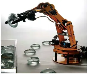
[image:16.595.231.379.616.739.2]The robotic arm is a useful device for surgical and industrial application which able performs movement on certain situation. The robotic arm movement and torque are measured based on the kinematic design. A robotic arm is a mechanical controlled device which is designed to do movement of a human arm. The robotic arm can be design by many actuators like pneumatic, hydraulic and motor. Due to the arm movement, it requires a type of controller for performing the movement. In this past, the types of controller use on robotic arm like PD controller, PI controller, and PID controller are used on force feedback arm robotic. Robotic arms are used in the medical field to carry out certain precise operations. The robotic arm also used in light and heavy industrial application as shown in Figure 1.1.
2 1.2 Motivation
Within past few decades, there has been an explosion of interest in robotic arm. Robotic arm are being utilized in high-performance application like manufacturing, surgical and many more. There are many difference robotic arm use in an application which has good and bad attributes. The bad attributes in a system which has cause the lag of efficiency. However, the next generation of robotic arm will need to estimate the proportional torque in industrial and surgical industry. The robotic arms are composed with Direct Current (DC) motor as an actuator. The DC motor can be implementing by using control strategies to control the output torque of the robotic arm.
1.3 Problem Statement
In the recent year, the robotic arm use rapidly increases in medical and industrial application. The robotic arm occurs problem like estimating the proportional torque in the motor. The inconsistent of voltage supplied into the motor cause the output torque produce is unstable. The main challenge in this project is to controlling the proportional output torque of robot arm.
3 1.4 Objective
The main objective of this project is to design a proportional-integral-derivative (PID) controller using DC motor for able to control the output torque of an upper limb robotic arm. The objective includes the development of controller, simulation, excitation circuits, and hardware interfacing. The summary of the objectives of this project are listed as follows:
1. To design and develop an upper limb robotic arm.
2. To design and develop a proportional-integral-derivative (PID) controller that able control output torque of an upper limb robotic.
3. To compare experimental result and simulation for the controller and DC geared motor.
1.5 Scope
In order to achieve the objective of the project, there are several scope had been outlined. The scopes are as follows:
1. To design and fabricate an upper limb robotic arm.
4
CHAPTER 2
LITERATURE REVIEW
2.1 Introduction
In this section, the kinematic of robotic arm, actuator, controller and literature review will be delivered. Robotic arm is a device used to many applications in industry and surgical. The development of an upper limb robotic arm is passively important and needed to research based on the type of application perform, actuator and the controller.
2.2 Upper Limb Robotic Arm
5 2.2.1 Kinematic of Upper-Limb Robot
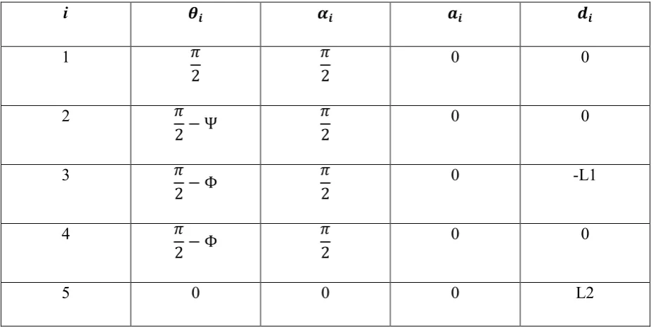
[image:20.595.137.474.267.468.2]A five degrees of freedom exoskeleton with wearable structure and anthropomorphic which cover the entire motion of human arm for upper-limb rehabilitation in virtual reality [1]. The proposed robot automatically assists by a button mainly based a controller able force at the center of human palm through a handle grasped by the user. The Light Exoskeleton (L-EXOS) is characterized by a serial kinematic which consist five rotational joint as shown in Figure 2.
Figure 2.1: The kinematics of light weight exoskeleton (L-EXOS) [1]
6 Table 1: Denavit-Hartenberg parameters for the light weight exoskeleton (L-EXOS system)
[1]
i
1 0 0
2 0 0
3 0 -L1
4 0 0
5 0 0 0 L2
2.3 Actuator
An actuator is a device which converts electric energy into a physical motion. The actuator produce rotation or linear motion based the application applied in the industry. There are several types of actuator use in robotic arm like hydraulic, pneumatic or electronic signals. The most popular actuator use in a robotic arm is DC motor. The DC motor is electric motor that runs on direct current electrically.
7 2.3.1 DC Motor
[image:22.595.124.482.323.526.2]A position control of brushless using DC (BLDC) motor proposed. DC (BLDC) motor is a synchronous electric motor which is controlled by direct current power (DC) and which has an electronically controlled system, rather than a mechanical replacement system dependent upon brushes [2]. In the brushless DC motor, the element like current, torque, voltage and rpm are directly identified. The advantage of brushless DC motor is good reliability, longer lifetime, reduced noise and more efficient in terms of power consumption. The disadvantage of brushless DC motor (BLDC) is higher initial cost due to its construction. Second, it required an electric controller in order to operate a Brushless DC Motor.
8 2.4 Sensory System
2.4.1 Hall Sensor
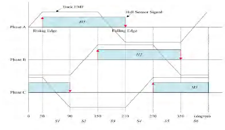
[image:23.595.110.502.350.577.2]Based on the Hall Effect sensor characteristic, the rotor rotation information can be acquired. The position and speed of the rotor can be calculated by using Hall Effect signal [3]. In the experiment, the hall sensor are placed in the brushless DC motor to knowledge the position of the motor. The hall is place with 120-degree interval in the motor operation. When the magnet poles of the interface to hall sensor, the signal is generated. There are three hall sensor planted to the brushless DC motor since it has 120-degree interval. For a one complete rotation, it has to reach 360-degree for determine the position of the brushless DC motor. The operating principle of hall sensor can be explained based on the Figure 2.3 shown.
9 2.4.2 Torque Sensor
Torque sensor is a characteristic of human arm where it can feel the external power. In order to know precisely the intentions of a human interacting with a robot, it is possible to use a force/torque sensor to measure the forces and moments applied on a handle. The advantage of this type of sensor, in comparison with a sensitive robotic skin covering the whole manipulator, is that it allows the precise measurement of the applied moments and shearing forces instead of the normal forces alone.
The commercially available force/torque sensors are built from strain gages, which have the disadvantage of providing a noisy signal. This is problematic because control algorithms used in human-robot interaction often require the variation rates of efforts. It differentiating noisy signals with respect to time is often only possible by filtering the signal, which reduces the performances of a collaborative robot [5]. Furthermore, force/torque sensors based on strain gages output signals which drift over time even if the applied efforts remain constant. Thus, a collaborative robot could detect small forces applied on it and start moving even if nobody touches it.
[image:24.595.193.414.568.703.2]A robust torque control is proposed for one degree arm robot which is equipped with torque sensor for controlling the output torque [5]. The mechanical structure of a one degree of freedom flexible joint robot is shown as Figure 2.4. A motor generate a driving torque and the torque is increase by speed reduction part. The speed reduction part is consisting of timing belt, pulley and harmonic drive. The joint torque is measure by a torque sensor which mounted between harmonic drive and robot arm link.
![Figure 2.1: The kinematics of light weight exoskeleton (L-EXOS) [1]](https://thumb-us.123doks.com/thumbv2/123dok_us/96762.9070/20.595.137.474.267.468/figure-kinematics-light-weight-exoskeleton-l-exos.webp)
![Figure 2.2: Brushless DC motor (BLDC) [2]](https://thumb-us.123doks.com/thumbv2/123dok_us/96762.9070/22.595.124.482.323.526/figure-brushless-dc-motor-bldc.webp)
![Figure 2.4: The mechanical structure of a one degree of freedom flexible joint robot [5]](https://thumb-us.123doks.com/thumbv2/123dok_us/96762.9070/24.595.193.414.568.703/figure-mechanical-structure-degree-freedom-flexible-joint-robot.webp)