DESIGN ANALYSIS OF SHEET METAL WELDED JOINT
BASED ON TRANSIENT THERMAL CONDITION
LAU LI YING
B051010051
UNIVERSITI TEKNIKAL MALAYSIA MELAKA
UNIVERSITI TEKNIKAL MALAYSIA MELAKA
DESIGN ANALYSIS OF SHEET METAL WELDING JOINT
BASED ON TRANSIENT THERMAL CONDITION
This report submitted in accordance with requirement of the Universiti Teknikal Malaysia Melaka (UTeM) for the Bachelor Degree of Manufacturing Engineering
(Manufacturing Design) (Hons.)
by
LAU LI YING
B051010051
901017-08-5652
UNIVERSITI TEKNIKAL MALAYSIA MELAKA
BORANG PENGESAHAN STATUS LAPORAN PROJEK SARJANA MUDA
TAJUK: Design Analysis of Sheet Metal Welded Joint Based on Transient Thermal Condition
SESI PENGAJIAN: 2013/14 Semester 2
Saya LAU LI YING
mengaku membenarkan Laporan PSM ini disimpan di Perpustakaan Universiti Teknikal Malaysia Melaka (UTeM) dengan syarat-syarat kegunaan seperti berikut:
1. Laporan PSM adalah hak milik Universiti Teknikal Malaysia Melaka dan penulis. 2. Perpustakaan Universiti Teknikal Malaysia Melaka dibenarkan membuat salinan
untuk tujuan pengajian sahaja dengan izin penulis.
3. Perpustakaan dibenarkan membuat salinan laporan PSM ini sebagai bahan pertukaran antara institusi pengajian tinggi.
4. **Sila tandakan ( )
SULIT
TERHAD
TIDAK TERHAD
(Mengandungi maklumat yang berdarjah keselamatan atau kepentingan Malaysia sebagaimana yang termaktub dalam AKTA RAHSIA RASMI 1972)
(Mengandungi maklumat TERHAD yang telah ditentukan oleh organisasi/badan di mana penyelidikan dijalankan)
(TANDATANGAN PENULIS)
Alamat Tetap:
571, Jalan Sekolah
Kampung Tawas
30010 Ipoh, Perak
Tarikh: _23 Jun 2014_____________
Disahkan oleh:
(TANDATANGAN PENYELIA)
Cop Rasmi:
Tarikh: _______________________
DECLARATION
I hereby, declared this report entitled “Design Analysis of Sheet Metal Welded Joint Based on Transient Thermal Condition” is the results of my own research except as
cited in references.
Signature : ___________________________
Author’s Name : LAU LI YING
APPROVAL
This report is submitted to the Faculty of Manufacturing Engineering of UTeM as a partial fulfillment of the requirements for the degree of Bachelor of Manufacturing Engineering (Manufacturing Design) (Hons.). The member of the supervisory is as follow:
i
ABSTRAK
ii ABSTRACT
iii
DEDICATION
iv
ACKNOWLEDGEMENT
I would like to express my sincere thanks of appreciation to my co-supervisor, Dr. Taufik for his guidance and encouragement for completing this report. I am so grateful for his patient and tolerance of my naive mistakes.
I acknowledge my sincere gratitude to my parents and family members for their love, support and advices motivation.
v
TABLE OF CONTENTS
Abstrack i
Abstract ii
Dedication iii
Acknowledgement iv
Table of Contents v
List of Tables ix
List of Figures viii
List of Abbreviations, Symbols and Nomenclatures xi
CHAPTER 1: INTRODUCTION 1
1.1 Background 1
1.2 Problem Statement 2
1.3 Objectives 3
1.4 Scope 3
1.5 Report Organization 4
1.6 Project Schedule 4
CHAPTER 2: LITERATURE REVIEW 6
2.1 Sheet Metal 6
2.1.1 Sheet Metal Forming 6
2.1.2 Sheet Metal Joining Process 9
2.1.3 Applications of Sheet Metal in Manufacturing 11
2.2 Welding Metallurgy 13
2.2.1 Resistance Spot Welding 14
2.2.2 Nugget Formation of Resistance Spot Welding 16
2.2.3 Resistance Spot Welding Parameters 17
2.2.4 Applications of Welding Metallurgy in Manufacturing 18
2.3 Materials 18
2.3.1 Materials in Welding Metallurgy 18
vi
2.3.3 Aluminium Alloy 5182 21
2.3.4 Plastic Condition of Aluminium Alloy 22
2.4 Heat Transfer in Welding 22
2.4.1 Convection 23
2.4.2 Conduction 24
2.4.3 Radiation 25
2.4.4 Thermal Theory and Concepts 26
2.4.4.1 Steady State Condition 26
2.4.4.2 Transient Condition 26
2.4.4.3 Heat Flux 27
2.5 Design and Analysis 27
2.6 Other Researches 28
2.7 Summary 30
CHAPTER 3: METHODOLOGY 31
3.1 Methodology Flow Chart 31
3.2 Phase 1 33
3.2.1 Title Selection 33
3.2.2 Problem Identifications 33
3.3 Phase 2 33
3.3.1 Literature Review 33
3.3.2 Data Collecting 34
3.3.2.1 Calculations of Convection Coefficient 34
3.4 Phase 3 36
3.4.1 Steady-State Thermal Analysis 37
3.4.2 Transient Thermal Analysis 42
3.5 Phase 4 49
3.6 Summary 50
CHAPTER 4: RESULTS AND DISCUSSION 51
4.1 Result 51
4.1.1 Steady State Thermal Analysis 51
vii
4.1.1.2 Reaction Probe 53
4.1.1.3 Factor of Safety 55
4.1.2 Transient Thermal Analysis 57
4.1.2.1 Total Heat Flux 57
4.1.2.2 Reaction Probe 58
4.1.2.3 Factor of Safety 60
4.2 Discussion 61
4.3 Summary 66
CHAPTER 5: CONCLUSION AND RECOMMENDATION 68
5.1 Conclusion 68
5.2 Recommendation for Future Study 69
REFERENCES 70
APPENDICES 75
A Drawing of sheet metal with thickness 1mm and two numbers of spot welds B Drawing of sheet metal with thickness 2mm and three numbers of spot welds C Drawing of sheet metal with thickness 3mm and four numbers of spot welds D Drawing of sheet metal with thickness 4mm and five numbers of spot welds E Drawing of sheet metal with thickness 5mm and two numbers of spot welds F Drawing of sheet metal with thickness 6mm and two numbers of spot welds G Report of steady state thermal analysis
viii
LIST OF TABLES
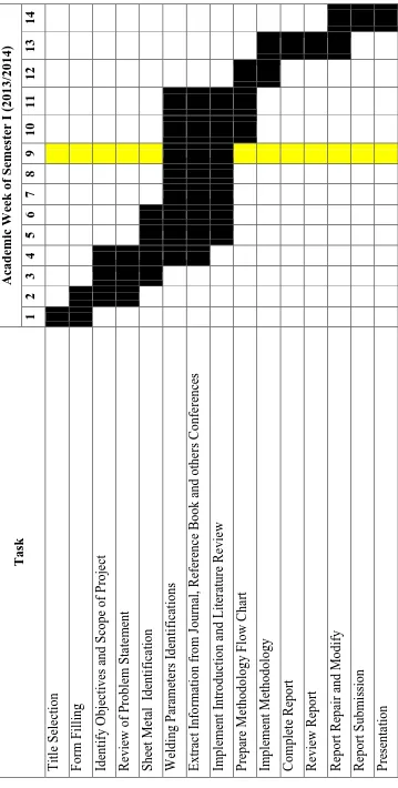
1.1 Project Schedule for Final Year Project I 5
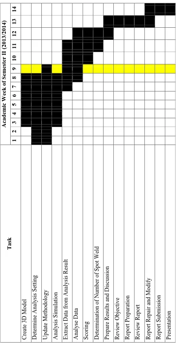
1.2 Project Schedule for Final Year Project II 6
2.1 Overview of Material with Joining Process 19
2.2 Typical Forms and Uses of Aluminium Alloys 20
2.3 Chemical Composition of Alumimiun Alloy 5182 21
2.4 Welding Parameters and Welding Cycle 29
3.1 Data Obtained 34
4.1 Total Heat Flux from Steady State Thermal Analysis 52 4.2 Reaction Probe from Steady State Thermal Analysis 54 4.3 Factor of Safety for Steady State Thermal Analysis 55
4.4 Total Heat Flux for Transient Thermal Analysis 57
4.5 Reaction Probe of Transient Thermal Analysis 58
4.6 Factor of Safety for Transient Thermal Analysis 60
4.7 Number of Spot Weld That Fulfil the Requirements 63
4.8 Scoring for Sheet Metal with Thickness 1mm 63
4.9 Scoring for Sheet Metal with Thickness 2mm 64
4.10 Scoring for Sheet Metal with Thickness 3mm 64
4.11 Scoring for Sheet Metal with Thickness 4mm 65
4.12 Scoring for Sheet Metal with Thickness 5mm 65
4.13 Scoring for Sheet Metal with Thickness 6mm 66
ix
LIST OF FIGURES
2.1 Schematic of Shearing Process 7
2.2 Punching and Blanking 7
2.3 Schematic Diagram of Deep Drawing 8
2.4 V-Shape Bending 8
2.5 Metal Stamping Products of Key To Metals Brazil. 9
2.6 Types of Seam Joint 10
2.7 Rivet 10
2.8 Bolt and Nut 11
2.9 Clinching Joint Cross-Section 11
2.10 Major Panels of Car Body 12
2.11 Draw and Redraw Method of Can Manufacture 13
2.12 Master Chart of Welding and Allied Processes 14
2.13 Welding Cycle 16
2.14 Nugget in Resistance Spot Welding 17
2.15 Temperature Range for Plastic Condition for Aluminium Spot Welding 22
2.16 Schematic of Convection 23
2.17 Natural Convection and Forced Convection 24
2.18 Schematic Diagram of Heat Conduction across a Wall 25 2.19 Schematic Diagram of Steady State Heat Conduction 26
2.20 Schematic Diagram of Transient Conduction 27
2.21 Test Piece 29
3.1 Methodology Flow Chart. 32
3.2 Steady State Thermal Analysis. 37
3.3 Sheet Metal with Thickness 4mm and 3 Spot Welds. 37
3.4 Meshing of 3D Model. 38
3.5 Steady State Thermal Analysis Constraint. 38
3.6 Setting for Temperature Constraint. 38
x
3.8 Transient Thermal Analysis with Solution. 39
3.9 Result of Reaction Probe of Steady State Thermal Analysis. 40 3.10 Result of Total Heat Flux of Steady State Thermal Analysis. 40 3.11 Transferred Solution from Steady State Thermal Analysis to Static Structural
Analysis. 41
3.12 Static Structural Analysis Setting. 41
3.13 Result of Factor of Safety for Steady State Thermal Analysis. 42
3.14 Transient Thermal Analysis. 42
3.15 3D Model of 6mm Thick Sheet Metal with 5 Spot Welds. 43
3.16 Mesh Generation. 43
3.17 Meshed 3D Model. 44
3.18 Temperature Constraint Setting. 44
3.19 Convection Constraint Setting. 45
3.20 Solution of Transient Thermal Analysis. 45
3.21 Solution of Reaction Probe for Transient Thermal Analysis. 46 3.22 Solution of Total Heat Flux for Transient Thermal Analysis. 46 3.23 Data Transferred from Transient thermal Analysis to Static Structural
Analysis. 47
3.24 Static Structural Analysis Setting for Transient Thermal Analysis. 47 3.25 Solution Setting for Static Structural Analysis in Transient Thermal Analysis.
48 3.26 Result of Factor of Safety for Transient Thermal Analysis. 49
xi
LIST OF ABBREVIATIONS, SYMBOLS AND
NOMENCLATURE
̇ - Rate of Conduction Heat Transfer (W)
̇ - Rate of Convection Heat Transfer (W) - Surface Area
- Temperature of Colder Object - Temperature of Hotter Object
- Fluid Bulk Temperature - Surface Temperature
- Thickness of Heat Transfer
A - Heat Transfer Area
Al - Aluminium
Cu - Copper
Fe - Iron
g - Gravitational Acceleration (m/s2)
h - Convection Heat Transfer Coefficient (W/m2.K)
I - Electric Current (Ampere)
k - Thermal Conductivity of Material (W/m.K)
Lc - Characteristic Length
Mg - Magnesium
Mn - Manganese
Nu - Nusselt Number
Pr - Prandtl number
Q - Total Energy (Joule)
R - Resistance (Ohm)
RaL - Rayleigh Number
Si - Silicon
t - Time (Second)
v - Kinematic Viscosity of fFuid (m2/s)
1
CHAPTER 1
INTRODUCTION
This chapter discussed the general idea of thermal transient condition for resistance spot welding of sheet metal. Others elements that included in this chapter are problem statement, objective, scope, and report organization.
1.1 Background
Sheet metal working are normally undergoes cold condition compared to formed under hot condition. This is because sheet metal has a lower resistance to deformation when heated (Boljanovic, 2004). The sheet metal forming processes included roll forming, stretch forming, drawing, stamping, rubble-pad forming, spinning, superplastic forming, poem forming, explosive forming and magnetic-pulse forming (Kalpakjian and Schmid, 2009).
Many methods have been used in joining materials together which are adhesive bonding, mechanical joining, fusion welding, solid state bonding welding, friction welding, electromagnetic welding, brazing and roll bonding (Imaizumi, 1996).
2 When a structure or part is produced by welding process, a non-uniform temperature distribution is created in the structure or part. A rapid thermal expansion and contraction in weld and the surrounding areas during welding process results in this temperature distribution. Thus, inhomogenous plastic deformation and residual stresses in the weldment is formed when the structure is cold (Armentani and et. al., 2006).
1.2 Problem Statement
Resistance spot welding process include the combination of thermal, electrical, mechanical and metallurgical phenomena. It is a complicated welding process (Nied, 1983). The complexity of this welding process had led to some difficulties in understanding the thermal behavior in the weldment (Cho and Cho, 1989).
After resistance spot welding process, the residual stress and strain will remain in the weldment due to the deformation during the welding process. Upon electrode force and heating, stress and strain will be created and changed. A numbers of researches of the mechanical features for resistance spot welding process are being done. As a conclusion from the researches, the factors that might lead to the failure of resistance spot welding are residual stress, welding schedule, nugget size, welding parameters, thickness, material properties and gap (Wang et al., 2009).
3 welded joint within the factor of safety based on transient thermal condition where the number of spot welds need to be determine.
1.3 Objectives
The objectives of this project are:
a. To investigate the design parameter of sheet metal welded joint. b. To analyze the transient thermal condition.
c. To propose the factor of safety of sheet metal welded joint.
1.4 Scope
In this project, the sheet metal welded joint is created by using resistance spot welding. The design parameters that investigated are material, dimension and thickness of sheet metal that used in this project. The material of the sheet metal is aluminium alloy 5182 with thickness between 1mm-6mm. The dimension of the sheet metal in this project is 120mm x 60mm. The numbers of spot welds are vary from two spot welds to five spot welds.
4
1.5 Report Organization
This report consists of three chapters where Chapter 1 of this report is introduction. This chapter included the general idea of transient thermal condition of resistance spot welding and the part included. This chapter also discussed the problem statement, objectives, scope, report organization and project schedule.
Chapter 2 is literature review where the review of previous studies that done by other researchers were included in this chapter. This chapter discussed the parameter of spot welding, thickness and materials of sheet metal. Also, this chapter included the design and analysis software that been used to carry out this project.
Chapter 3 methodology described the method that used to achieve the objectives. A flow chart is presented to illustrate the steps and overall process flow of this project. The steps in carried out the analysis using ANSYS were discussed in this chapter too. Chapter 4 included the results and discussion for this project. The results obtained from the analysis were tabulated and discussed. The suitable numbers of spot welds were suggested at the end of this chapter.
Chapter 5 summarize the whole report and recommend for future work that can be done regarding to this project.
1.6 Project Schedule
6
CHAPTER 2
LITERATURE REVIEW
This chapter is discussed the concepts and theory of sheet metal forming and joining process and welding metallurgy. This chapter also discussed the transient thermal condition of resistance spot welding. Also, other researches that had been done by other researchers are included in this chapter too.
2.1 Sheet Metal
According to The Aluminium Association, aluminium sheet is a product that is rectangular in cross-sectional and form, with thickness more than 0.20mm and less than 6.30mm. A sheet is known as plate if the thickness exceed or more than 6.30mm (The Aluminium Association, 2007).
2.1.1 Sheet Metal Forming
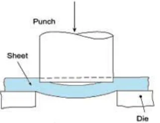
The methods that are most often being used for sheet metal forming are shearing, punching and blanking, deep drawing, bending and other processes (Boljanovic, 2004). Among the methods, shearing, punching and blanking are cutting process.
7 shearing process. The sheet metal experienced shearing process or being cut by the punch and die where force is added. This process is usually used to produce various opening in a sheet metal (Kalpakjian and Schmid, 2009).
Figure 2.1: Schematic of Shearing Process (Stuart, 2002-2013)
Blanking and punching (also known as piercing) are both shearing process. The main difference of these two processes is the scrap. Figure 2.2 shows the difference between punching and blanking operations. Punching operation is whereby the scrap the part that had been cut out. The workpiece of blanking is called a blank. This is the part which cut off during the process (Totre et al., 2013).
Figure 2.2: Punching and Blanking (Khan and Haque, 2011)
[image:24.595.204.436.433.520.2]