USING FRANKFORT HORIZONTAL PLANE - A
CEPHALOMETRIC COMPARATIVE STUDY
Dissertation submitted to
TAMIL NADU DR.M.G.R.MEDICAL UNIVERSITY
In the partial fulfillment of the degree of
MASTER OF DENTAL SURGERY
PART II – BRANCH I – PROSTHODONTICS AND
CROWN & BRIDGE
MARCH 2011
This is to certify that this dissertation titled “Geometrical Analysis of
Occlusal Plane Using Frankfort Horizontal Plane – A Cephalometric
Comparative Study” is a bonafide record of work done by Dr. Neha Sood under my
guidance during his postgraduate period between 2008- 2011. This Dissertation is
submitted to THE TAMILNADU Dr. M.G.R. MEDICAL UNIVERSITY, in
Partial fulfilment of requirements for the Degree of Master of Dental Surgery in
Prosthodontics and Crown & Bridge (Branch 1).
It has not been submitted (partial or full) for the award of any other degree or
diploma.
GUIDE HEAD OF THE DEPARTMENT
Dr. C. SABARIGIRINATHAN, M.D.S. Dr. C. THULASINGAM, M.D.S.
Senior civil Surgeon Professor & Head
Associate Professor Department of Prosthodontics
Department of Prosthodontics Tamilnadu Government Dental & Tamilnadu Government Dental College College & Hospital, Chennai – 03 & Hospital , Chennai - 03
PRINCIPAL
Dr.K.S.G.A.NASSER, M.D.S.
I, Dr. Neha Sood, do hereby declare that the dissertation titled “Geometrical
Analysis of Occlusal Plane Using Frankfort Horizontal Plane – A Cephalometric
Comparative Study” was done in the Department of Prosthodontics, Tamil Nadu
Government Dental College & Hospital, Chennai - 600 003. I have utilized the
facilities provided in the Government Dental College for this study in partial
fulfillment of the requirements for the degree of Master of Dental Surgery in the
speciality of Prosthodontics and Crown & Bridge (Branch I) during the course
period 2008-2011 under the conceptualization and guidance of my dissertation Guide
Dr. C. Sabarigirinathan, M.D.S.
I declare that no part of the dissertation will be utilized for gaining financial
assistance for research or other promotions without obtaining prior permission from
the Tamil Nadu Government Dental College & Hospital.
I also declare, that no part of this work will be published either in the print or
electronic media except with those who have been actively involved in this
dissertation work, and I firmly affirm that the right to preserve or publish this work
rests solely with the permission of the Principal, Tamil Nadu Government Dental
College & Hospital, Chennai 600 003, but with the vested right that I shall be cited as
the author(s).
Signature of the PG Student Signature of the HOD
I consider it my utmost privilege and honour to express my most sincere and
heartfelt gratitude to my esteemed Chief Dr. C.THULASINGAM, M.D.S., Professor
and Head, Department of Prosthodontics, Tamilnadu Government Dental College and
Hospital for his wholehearted support, guidance, help, encouragement and also for
constant inspiration throughout the period of my post graduate course.
My sincere thanks to Dr. K.S.G.A. NASSER, M.D.S., Principal, Tamil Nadu
Government Dental College and Hospital, for his kind help, and for permitting me to
use the facilities in the institution.
I am extremely thankful to my Guide Dr. C. SABARIGIRINATHAN, M.DS.,
Senior Civil Surgeon, Associate Professor, Department of Prosthodontics, Tamil
Nadu Government Dental College and Hospital for the invaluable suggestions and
support that he has rendered at various stages of the dissertation. Without his help this
dissertation would not have come out in a befitting manner. I also thank him for
extending extreme support and encouragement throughout the period of my post
graduate course.
I would like to express my thanks to Dr. A. MEENAKSHI, M.D.S., and
Additional Professor, Department of Prosthodontics, Tamil Nadu Government Dental
College and Hospital, for all the inspiration and guidance she has provided throughout
Dr. RUPKUMAR, M.D.S., Dr. T. JEYANTHIKUMARI M.D.S., Dr. G
SRIRAMPRABHU M.D.S., Dr. G. GOMATHI M.D.S., Dr. K. RAMKUMAR
M.D.S., Dr. M. KANMANI M.D.S., Dr. HARISHNATH, M.D.S., and for guiding
and helping me at different stages of this study.
I thank Mr. RAVANAN, Reader, Department of Statistics, Presidency College,
and Chennai for helping me with the statistical analysis for this study.
I thank Mr. Shakti, Technician, Department of Oral Medicine and Radiology
for helping me in the dissertation work.
I am thankful to my senior Dr. R. Cholan, M.D.S., Dr. B. and my fellow post
graduate Dr. Jayesh Jain for helping me right through my dissertation work.
I am extremely thankful to Dr. Mittali Sethi, Dr. B. Anand, and Dr. Deepa for
their timely help.
I am very thankful to my friend Dr. Anurag Mehta for helping me right
through my dissertation work.
I thank my parents for being with me throughout and above all I thank
ALMIGHTY for giving me the courage to finish this task.
S.No Contents
Page
No.
1 Introduction
1
2 Aim
and
Objectives
6
3
Review of Literature
7
4
Materials and Methods
27
5 Results
40
6 Discussion
52
7
Summary and Conclusion
62
8 Bibliography
9 Appendices
S No
Abbreviation
Expansion
1
ANOVA
Analysis of Variance
2 HIP
Hamular
notch-Incisive
Papilla
plane
3 kVp
Kilo
Voltage
Potential
4
OP
Occlusal Plane
5 FH
Frankfort Horizontal plane
6 AT
Ala-Tragus line
7 mA
Milliamperes
8 mm
Millimeters
S No TITLE Page No
1a Armamentarium for clinical examination
1b Armamentarium for impression procedures
1c Armamentarium for record base and occlusal
rim fabrication
1d Armamentarium for Cephalometric tracing
1e Cephalostate
1f Wills Surveyor
2 Cephalogram taken for the dentulous patient
3a Primary Impressions
3b Primary Casts
4a Secondary Impressions
4b Secondary Casts
5 Record bases and Occlusal rims
6a Representative of Group II-A height of the
occlusal rim adjusted anteriorly 2mm below the
resting upperlipline
6b Anterior plane established parallel to the inter
7a Representative of Group II-B Anterior plane
established in level with lower lip
7b Retromolar pad areas marked on the cast
7c Posterior plane established in level with the
junction of middle and upper third-occlusal
view.
7d Lateral view
7e Intraoral view
8a Representative of Group II-B height of the
occlusal rim adjusted anteriorly 2mm below the
resting upper lipline
8b Anterior plane established parallel to the
interpupillary line.
8c Establishing HIP parallel to the floor of the
surveyor –Fixed vertical arm in contact with
the incisive papilla on the cast.
8d fixed vertical arm in contact with the hamular
notch on the cast –right side
8e On the left side.
8f Posterior plane of the occlusal rim established
parallel to the HIP and floor of the surveyor.
9 Occlusal rims with representative of Group –II
A, B & C, lead foil adapted and secured with
11a Cephalogram representative of Group I
11b Cephalometric tracing done
12a Cephalogram representative of group II A
12b Cephalometric tracing done
13a Cephalogram representative of Group II B
13b Cephalometric tracing done
14a Cephalogram representative of Group II C
S No Title Page No
Table I and II
Basic values of the angle obtained between Occlusal
plane and Frankfort Horizontal plane for Group I 39
Table III Basic values of the angle obtained between Occlusal
plane and Frankfort Horizontal plane for Group II A,
Group II B, and Group II C
40 & 41
Table IV Mean values of the angle between OP and FH in Group
I, Group II A, Group II B, and Group IIC and their
standard deviation
42
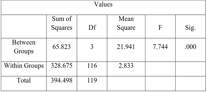
Table V Sum of squares of the mean values between the groups
and within the groups
.
42Table VI Mean difference between Group I and Group II A,
Group II B, Group II C 43
Table VII Mean difference between Group II A and Group I,
Group II B and Group II C 43
Table VIII
Mean difference between Group II B and Group I,
Group II A and Group II C. 44
Table IX Mean difference between Group II C and Group I,
Group II A and Group II B 44
Table X Means for groups in homogenous subsets 45
S No Title Page No
Fig 1 Mean values for the angle between Occlusal plane and
Frankfort Horizontal for Group I, Group II A, Goup II B,
and Group II C and their standard deviation
Fig 2 Sum of the squares of the mean values between the
groups and within the groups
Fig 3 Mean difference between Group I and Group II A,
Group II B, Group II C
Fig 4 Mean difference between Group II A and Group I,
Group II B, Group II C
Fig 5 Mean difference between Group II B and Group I,
Group II A, Group II C
Fig 6 Mean difference between Group II C and Group I,
Group II A, Group II B
Fig 7 Means for groups in a homogenous subsets
[image:12.612.107.509.114.554.2]
Introduction
“The occlusion of the teeth is the most potent factor in determining the
stability in the new position.” This was written by Kingsley in the nineteenth century
and will always hold true.
Complete Denture Prosthetics is the dental specialty, which places the greatest
number of important factors in the control of the operator. Here the Operator is
concerned with the shape, size, and relative position of the ridges; the positioning of
the artificial teeth in relation to the ridges; the arrangement of the anterior teeth for
esthetics; the determination of the incisal guidance angle; condylar function and the
combined influence of the incisal guidance angle and condylar function on the
orientation of the plane of occlusion and the curve of Spee.
All these factors must be carefully considered in order to provide dentures that
function successfully. One can, without going into detail, appreciate the modifications
of tooth form and size required by alterations in condylar function, the incisal
guidance angle, the Curve of Spee, and the orientation of the plane of occlusion. The
interrelation of these various factors is conspicuously apparent. The more guides there are to these factors, the simpler the task. Various methods of recording mandibular
function, vertical dimension, incisal guidance angle, and tooth form have been
devised and advocated.
Occlusal plane position is the foundation of clinical treatment and one of the
Introduction
is being done in this area; unfortunately little clinical application has filtered into
treatment procedures.
In complete denture construction, the prosthodontist is responsible for
restoring the natural esthetics of the patient and for developing an occlusion that is
compatible with the functional movements of the mandible. From the functional
viewpoint, the occlusal table is a milling surface, strategically placed so that the
tongue on the lingual side and the buccinator muscle on the buccal side are able to
position the food bolus onto it and hold it there while mastication takes place.
According to the Glossary of Prosthodontic terms, the occlusal plane is
defined as“the average plane established by the incisal and occlusal surfaces of the
teeth. Generally, it is not a plane but represents the planar mean of the curvature of
these surfaces.”
The orientation of occlusal plane is lost in patients rendered edentulous and
should be relocated if complete dentures are to be aesthetic and to function
satisfactorily. Where the occlusal plane is too high, the tongue cannot rest on the
lingual cusps of the lower denture and prevent its displacement. There is also a
tendency for accumulation of food in the buccal and lingual sulci. An occlusal plane
that is too low, could lead to tongue and cheek biting.
The correct orientation of the occlusal plane plays a vital role in optimal
Introduction
lower lip. If the plane hangs posteriorly, the lip line viewed from the front will appear
straight and contribute more than any other factor to the so called “Denture look”.
With the occlusal plane correctly oriented, however the natural anterior curve will be
achieved almost automatically and contribute a proper sense of perspective to the
dental composition.
The function and esthetics of removable prostheses are dependent on the
correct orientation of the occlusal plane. Many theories and methods have been
proposed over the years to facilitate correlation of the artificial occlusal plane to the
natural one. The precise location of the occlusal plane for edentulous patients is a
controversial matter. There appears to be a lack of agreement on how it should be
orientated for individual patients.
Camper's line, postulated in 1780 by the Dutch anatomist Peter Camper,
extendsfrom the alae of the nose to the center of the external auditory meatus and is
widely used as a guide in the orientation of the occlusal plane. There are intraoral
landmark which are used by the authors to determine the occlusal plane, these include
height of retromolar pad, the buccinators grooves, commisures of lips, and lateral
border of the tongue.
However, in the edentulous patient, locating the occlusal plane in the same
position as it was when natural teeth were present is ideal. The occlusal plane should
be established as nearly as possible to the position of occlusal plane of the natural
Introduction
Anthropologists have long studied the ethnographic determination of facial
form and pattern. By studying different ethnic, age, and sex groups and by measuring
the size of the various parts and recording variations in position of cranial and facial
structures , broad standards were devised that describe the human head . As a
specialised part of anthropometry, “the measurement of man”, study of the head
became known as “craniometry” or “cephalometry”.
Cephalometric analysis has served for many years as a valuable adjunct to
dental research and diagnosis. Although its clinical application has been directed
largely toward orthodontics, yet cephalometrics is valuable tool in Prosthodontics to
re-establish the spatial position of lost structures such as the teeth. This is achieved by
identifying predictable relationships between the teeth and other cranial landmarks
that are notsubject to post extraction changes.
Frankfort Horizontal plane has long been considered as a reliable reference
plane used for cephalometric analysis in Orthodontics. Its use in Prosthodontics is
documented with equal success and it can serve as a useful reference plane in
performing cephalometric studies in edentulous patients.
The search for a method that establishes an occlusal plane that is in complete
harmony with the enviorenment of an edentulous situation is yet not accomplished.
The present study was undertaken to evaluate and establish an occlusal plane in
edentulous patients that more closely resembles the one occurring naturally. Three
Introduction
parallel to the plane between the corner of the mouth and the junction of middle and
upper third of the retromolar pad, and parallel to Hamular notch-Incisive Papilla plane
to evaluate the most physiologic position of occlusal plane in Complete Denture
wearers.
The Null hypothesis was presumed as, all the three methods used to establish
the occlusal plane in edentulous patients tend to position it close to the one that occurs
Aim:
To evaluate and establish a reliable method of occlusal plane
determination in edentulous individuals
Objectives:
1. To evaluate the close relationship of the occlusal plane established in
edentulous group with that of dentate individuals.
2. To determine the reliability of Camper’s plane, junction of middle and upper
third of the retromolar pad, and Hamular notch-Incisive Papilla plane to
establish the occlusal plane in edentulous individuals.
3. Cross verifying the results obtained from the dentulous group to the
edentulous subjects.
The occlusal plane position is the foundation of clinical treatment and one of
the most important criteria used to judge the degree of treatment success. It is an
important factor which harmonizes morphology and function of stomatognathic
system.
Various authors have defined the occlusal plane in many different ways. The
various definitions of the occlusal plane in the literature are as follows:-
1.
“An imaginary surface that touches the incisal edges of incisors and tips of
the occluding surface of the posterior teeth”.1
2.
“A line bisecting the molar and incisor overbite”.2
3.
“A line extending from mesio incisal angle of upper central incisor to the
mesiopalatal cusp of first maxillary molars”.3
4.
It represents the functional table of occlusion in the first permanent molar,
second premolar and the first premolar area.
5.
a.The average plane established by the incisal and occlusal surfaces of the
teeth. Generally, it is not a plane but represents the planar mean of the
curvature of these surfaces.
b.The surface of wax occlusion rims contoured to guide in the arrangement of
denture teeth.
c. A flat metallic plate used in arranging denture teeth - comp to curve of
This review of literature aims to clarify the various concepts concerning the
occlusal plane orientation and the different techniques followed by various authors in
their attempts to correctly orient the occlusal plane. It was also necessaryto stress the
importance of finding sound principles for proper orientation of the occlusal plane in
Complete Denture Prosthodontics. The following are the reviews given by various
authors for the orientation and establishment of the occlusal plane.
Robert B. Sloane and Jack Cook, 19536performed a study to determine whether or
not there was any correlation between fixed cranial landmarks and the plane of
occlusion. It was concluded that;
1. Cook’s plane forms an angle with the plane of occlusion which falls within
predictable limits.
2. The angle formed by Cook’s plane and the plane of occlusion is related to
the distance from the anterior nasal spine to the hamular notch. The greater
the distance, the more acute the angle; the shorter the distance, the more
obtuse the angle.
3. Though there is a certain bilateral asymmetry in the skulls and casts
measured. It is negligible in its effect on the basic correlations.
4. Though the distances from the anterior nasal spine and the hamular
notches to the plane of occlusion varied, the difference between the two
measurements approached a constant, enough to permit the practical use of
5. Within esthetic considerations, the anterior aspect of the plane of occlusion
should be kept parallel to the pupils of the eyes.
Also from the study it was concluded that, it is important to select points of
references that would not be affected by the degenerative process and that could
readily be identified on the edentulous maxillary casts. Since the ANS is difficult to
locate on the edentulous maxillary cast, incisive papilla seems to be a viable option.
Howard J. Merkeley, 19547 advocated the use of vestibular impressions for
the location of occlusal plane. A series of four vestibular impressions were made in an
effort to analyze the exact location, effect, and various and changing applied action of
the accessory masticatory muscles, during the masticatory cycle. The subject had
natural dentition and the teeth were barely occluded and the impression material was
plastic. The first impression was made with the lips protruded, and so maintained until
the impression had set. The impression showed 1) A deep horizontal groove that had
been made by the horizontal fibres of the buccinators muscles when they were
stretched during lip protrusion.
2) A triangular depression where the stretched fibres of the triangularis muscle
impinged on the impression material. The bottom of the groove cut by the buccinators
muscle proved to correspond with the occlusal plane. This suggested a simple method
of locating the correct position for the occlusal plane for complete dentures. The
technique is to make bilateral vestibule impression with the trial bases in place and
the buccinators muscle is perforated by a line of holes reaching into the wax base, and
the occlusal plane is adjusted to this line of holes.
Hall WA, 1958,8 proposed that each patient’s occlusal plane is consistent with
his oral physiology and esthetic requirement. To orient any plane in space, 3 points
must be located. In the denture space, one is located in the anterior region, and one is
in each of the posterior segments. The anterior height of the occlusal plane is
determined by the length of the incisal edge of the upper occlusion rim above or
below the upper lip while it is in repose and when the lip is properly supported. The
two posterior points of orientation of the occlusal plane fall within the height of the
distal half of the retromolar pad. The entire plane is parallel to the ridge planes.
Smith ES, 19589 stated that the height of the occlusal plane anteriorly should
be in harmony with the type of lip. Rather than to follow a set rule for establishing the
anterior segment of this plane slightly below the border of the relaxed upper lip, as is
so often recommended, the plane of orientation should be above and hidden if the lip
is long and flexible, or it should be below and plainly in view if the lip is short, tight,
and tense. It is only for those patients who have lips of average length that the plane
of orientation should be slightly below the relaxed upper lip. From the frontal aspect,
the plane of orientation should be horizontal. It may not be parallel with a line through
the pupils of the eyes, as this line is not always horizontal. The plane of orientation
should be parallel with the floor as the patient stands erect. An estimation of this
parallelism can be made easily by observation while the dentist stands at arms’ length
approximate height of the plane posteriorly can be estimated by placing the tip of
one’s index finger over the mandibular ridge. Then while the mandible is thus held in
a position of approximate centric relation, the imaginary plane can be projected
posteriorly. If the plane is properly located, it will intersect the retromolar pad at or
near its base.
McGee GF, 196010 proposed that the triangular retromolar pads are outlined in pencil on the lower edentulous cast, and marks are made on the cast opposite the
apex of the triangle. The pads are bisected in an anteroposterior direction, and marks
are also made on the cast opposite these points. The first mark indicates the position
of the distal surface of the second molar, and the second mark indicates the height of
the occlusal plane. The occlusal plane to retromolar pad relationship may be observed
on any lower cast of natural teeth where the third molars are missing. The older
method of placing the occlusal plane at a point midway between the upper and lower
edentulous ridges often places it too high in relation to the lower ridge. The additional
leverage thus created usually causes discomfort to the denture patient and instability
of the denture. It was also confirmed that the incisive papilla remains in a constant
position. Even after the removal of teeth the papilla remains in its original position.
However, because of progressive bone loss, especially that of the labial plate, an
illusion is produced and the papilla seems to move forward.
Boucher CO, 196311, was of the opinion that the occlusal plane should be
oriented exactly as it was when the natural teeth were present. Thus, with the anterior
occlusal plane located approximately level with the top of the retromolar pad, the
factor of orientation of the occlusal plane is fixed. If the relation of the soft tissues to
the occlusal plane is important, the orientation of the occlusal plane becomes the third
factor of occlusion.
Malson TS, 196412, proposed that Anatomic landmarks in the mouths of
edentulous people can be used to locate accurately the height of the distal end of the
occlusal plane. A straight edge placed on top of the lower cuspid and in contact with
the crest of the highest cusp of the most posterior tooth in the mouth of a dentulous
person will contact the retromolar pad about one quarter of the distance from its top.
This phenomenon occurs even though some of the posterior teeth may have been lost
and regardless of the age of the patient. Therefore, one quarter of the distance from
the top of the retromolar pad is a reliable anatomic landmark for the height of the
distal end of the occlusal plane.
Ismail YH and Bowman JF., 196813 conducted a roentgenographic
cephalometric investigation to compare the position of the occlusal plane of the
artificial teeth with that of the natural teeth which existed before the remaining teeth
extracted. Occlusal plane of the trial dentures was first oriented to parallel the
ala-tragus line and then modified so that the occlusal surfaces of the second molars were
placed at the level of the middle third of the retromolar pad. This location of the
artificial occlusal plane was found to be at a lower level than the natural one in the
positioned so that the second molars are placed at the level of the upper third of the
retromolar pad.
Lundquist DO and Luther WW, 197014, undertook an investigation to
determine whether certain intraoral landmarks could accurately predict the location of
occlusal plane. The relationship between the plane of occlusion and the retromolar
pad, the parotid papilla, the buccinator grooves, and the commissure of the lips was
evaluated in subjects with ideal occlusions of natural teeth. Because of the close
correlation found among the occlusal plane, the buccinators grooves, and the
commissures of the lips, a vestibular impression technique is suggested for
determining the location of the occlusal plane in completely edentulous individuals.
Javid NS, 197415 stated thatit is difficult to establish a correct occlusal plane
without using an extra device (tongue blade, ruler, or the like). A J-shaped aluminum
device, called a “J plane” for use with a Fox planet to establish the occlusal plane was
suggested. Place the narrow side of the J plane against the nasion with its long axis
passing through the interpupillary line. The position of the anterior border of the Fox
plane should be parallel with the border of the J plane.
L’Estrange PR. and Vig PS., 197516, conducted a study in dentulous and
edentulous subjects to determine the location of occlusal plane as related to the
maxillomandibular space. The results from both the dentulous and edentulous groups
indicate a close angular affinity between the occlusal and maxillary planes. In the
occlusal plane to the maxillary plane and the height and length of the
maxillomandibular space. The occlusal plane in the long-and-low type of
maxillomandibular space tends to be more parallel to the maxillary plane, while the
occlusal plane in the short-and-high types of maxillomandibular space tends to be
more steeply angulated to the maxillary plane. The occlusal plane deviates away from
a mean angulation to the maxillary plane when the height and length of the
maxillomandibular space tend to be toward the opposite extremes of the normal
range.
Carey PD, 197817, conducted a study to test masticatory efficiency when tile
orientation of the occlusal plane was varied. Complete dentures were constructed for
subjects. Following three types of occlusal plane were constructed;
• Occlusal plane A -correspond with the lower border of the retromolar
pad.
• Occlusal plane B - correspond with the junction of the lower and
middle third of the retromolar pad.
• Occlusal plane C - correspond with the junction of the upper and
middle thirds of the retromolar pad.
From the results obtained in this study it would appear that within certain
limits function was not appreciably affected and that a certain amount of leeway is
Okane et al, 197918, conducted a study to investigate the effect of
anteroposterior inclination of the occlusal plane on muscle activity during clenching
and biting force and to estimate physiologically the applicability of the ala-tragus line.
The integrated electromyographic activity and biting forces of patients were examined
at three different anteroposterior inclinations of the occlusal plane at a constant
vertical dimension of occlusion. The followingconclusions were reached;
1. Biting force during maximum clenching was the greatest when the occlusal plane
was made parallel to the ala-tragus line. It decreased when the occlusal plane was
inclined about 5 degrees anteriorly or about 5 degrees posteriorly.
2. The efficiency of biting force exertion during maximum clenching showed the
best value when the occlusal plane was made parallel to the ala-tragus line.
3. Muscle activity during clenching at various given forces was least when the
occlusal plane was made parallel to the ala-tragus line.
Douglas JB et al, 198319 A cephalometric continuing longitudinal
investigation was to study the changes on the craniofacial complex in complete
denture wearers; herein are reported the 20-year findings.
1. The mandible auto rotated in a counterclockwise direction resulting in the loss
of vertical dimension of occlusion (decrease on lower face height) and an
increase in relative prognathism (class III appearance).
2. The mandibular bony edentulous ridge height was significantly reduced; the
3. The dentures exhibited a slight counterclockwise rotation and a slight anterior
shift.
4. Statistically there were no significant differences between men and women
and no significant differences between the groups wearing the standard
dentures compared with the group wearing the complex dentures.
Tuncay OC. Et al, 198420,analyzed the longitudinal cephalometric head films of
edentulous patients over a 10 year period. The purpose of the investigation was to
document changes within the craniofacial complex, residual ridge resorption, and
position of the dentures. The changes were correlated with the following variables:
age, sex, skeletal pattern, number of years edentulous, technique of denture
fabrication, and night time wearof the dentures.
Findings in this study suggest the following;
1. The maxillae and the mandible showed sagittal spatial counterclockwise
displacement.
2. Complete dentures exhibit a counterclockwise rotation and forward
movement.
3. Soft tissue seating is more important than alveolar ridge resorption in the
positional changes of complete dentures.
4. Variation in denture techniques had no influence on the observed changes.
5. Artificial porcelain teeth did not show a measurable amount of attrition during
6. Observed changes were not significantly affected by variables such as sex,
year’s edentulous, night time wear, or skeletal pattern. Two exceptions were
that the skeletal pattern affects prognathism and number of years edentulous
affects mandibular ridge resorption.
Van Niekerk FW., 198521, conducted a cephalometric study where complete
dentures were fabricated with criteria other than the ala-tragus line used to establish
the occlusal plane. Patients were completely satisfied with esthetics, function, and
comfort. Lead foil adapted to the right mandibular posterior teeth indicated the
occlusal plane. A strip of foil taped to the face pointed at the inferior borders of the
ala and tragus. The study concluded that ala-tragus line has a close relationship with
the occlusal plane and could be used as a landmark when the maxillary occlusion rim
is trimmed to the occlusal plane. Positioning of the occlusal planedepends on mature
clinical judgment and must ultimately satisfy esthetics, function, and denture stability.
Monteith BD., 198522, conducted a study to investigate the possibility of a
correlation between the PoNANS (Porion-Nasion to Anterior nasal spine) angle and
the occlusal angle formed by the intersection of the occlusal and Frankfort planes.
The results obtained appear to uphold the hypothesis: an increase in the PoNANS
angle has a flattening effect on the orientation of the occlusal plane, while a
narrowing of the angle appears to force the occlusal plane into assuming a steeper
important benefit that if one of them is absent, its best value can be predictedfrom the
measured value of the other.
Monteith BD., 198623, continued the study the accuracy with which an earpiece
face bow can transfer the Frankfort horizontal and the reliability with which a
PoNANS angle produced occlusal plane orientation is consistent with a natural
looking dental composition. The difference between the radiographic and predicted
occlusal plane angles was such that the final angle obtained was in no case greater
than that originally intended. The flattening effect observed could be ascribed to an
idiosyncracy manifesting as a tendency to locate the orbitale reference on the
patient’s face at a point slightly higher than its corresponding bony level.
Alternatively, the weight of the face-bow might have been sufficient to cause the
ear-rods to sag slightly, thus lowering the posterior reference point.
Chaconas SJ., 198624, proposed that there is a strong clinical indication that TMJ
problems can occur when the posterior position of the occlusal plane is the furthest
from the center of the ramus (Xi point). Therefore the occlusal plane should pass
through the center of the ramus to ensure proper occlusal function. This plane usually
passes through the superior half of the retromolar pad clinically.
Karkazis HC and Polyzois GL, 198725, conducted a Cephalometric study on
eighteen dentulous subjects and fifty-six complete denture wearers to determine the
location of the natural and artificial occlusal planes as related to Camper's plane.
1. The natural occlusal plane was not parallel to Camper's plane. The
deviation between the two planes varied from -5° to +9° with an
average of 2.88°.
2. The artificial occlusal plane determined at the delivery appointment on
processed complete dentures was not parallel to Camper's plane. The
deviation between the two planes varied from - 7 to +13° with an
average of 3.25°.
3. The final anteroposterior inclination of the artificial occlusal plane on
processed complete dentures was almost the same as the inclination of
the natural occlusal plane.
Di Paolo RJ, 198726, presented a method that uses cephalometric lateral films
to determine the occlusal plane position for the individual patient.
1. A relationship exists between the occlusal plane position and the lower-face
skeletal pattern of the patient.
2. The occlusal plane position can be determined after identifying the individual
skeletal pattern present.
3.
Identifying the occlusal plane position becomes an important factor in
dentistry, especially in procedures in which changes occur in the occlusal
Sinobad D, 198827, conducted a cephalometric investigation to evaluate the
spatial position of the occlusal plane to certain cranial landmarks in dentulous subjects
with various skeletal jaw-relationships. The aim of the investigation was to establish
the differences in its position in various natural occlusions which can be used as
predictable guides in prosthetic treatment of edentulous patients. According to the
results obtained no significant associations were observed between the position of the
occlusal plane to the maxillary plane and skeletal relation of the jaws. However,
concerning its relation to the mandibular plane, significant differences were found
between the groups with various skeletal classes. This can be connected with the
various positions of the mandible relative to the maxilla in various types of natural
occlusions.
Richard KK, and Djeng SK, 198928, Craniofacial reference lines
representing anatomic planes with prosthodontic importance were studied together
with the angles reflecting maxillary dimensions for dentulous Chinese (Singaporean)
adults by the use of lateral skull radiographs. The ala-tragus line showed high
variability when oriented to the maxillary occlusal line and could limit its use as an
index for the occlusal plane. A vertically high and horizontally receded upper face
was found in Chinese subjects, which contrasted significantly with the norms
reflected in a white (North American) population. These significant differences in
skeletal pattern of the maxillary region could account for an increase in inclination of
the Frankfort Horizontal plane for the Chinese subjects compared with the white
Richard KK and Djeng SK, 199029, conducted a study on dentulous Chinese
adult men with lateral skull radiographs. The orientation of the plane of occlusion was
analyzed in relation to traditional Prosthodontics planes. The use of the Frankfort
Horizontal line in the assessment of occlusal line orientation was limited, attributing
to the acknowledged variation of the Frankfort Horizontal line inclination between
Chinese and Swedish (white) patients. The inclination of the maxillary occlusal line to
Camper’s line was significantly shallower by 1.6 degrees for Chinese Singaporean
men compared with Swedish men. This difference was an indication that the anatomic
cant of the occlusal line was shallower for the Chinese patients. The procumbent
position of incisors characterized by Chinese patients is a major ethnic factor that
accounts for the diminished inclination of the occlusal plane.
Karkazis HC, Polyzois GL., 199130, conducted a cephalometric study to
check the hypothesis that the angulation of the occlusal plane is generally related to
the skeletal base of the maxillae.
The following conclusions were made;
1. No evidence was found that any of the three studied parameters (Cook’s plane,
ANS-PNS, and PO Na ANS) could be used as a reliable guideline for
determination of the occlusal plane through a regression formula.
2. The HIP plane tends to parallel the occlusal plane, giving one more guideline
3. Monteith’s formula cannot determine the occlusal plane in edentulous
subjects, although it provides occlusal planes closely oriented to the clinically
determined ones.
Kazanoglu A. and Unger JW, 199231, presented a device called Camper’s plane
indicator to be used for establishing the plane of occlusion in complete dentures. This
device is simple, practical, and accurate with all the necessary parts assembeled in one
instrument and, in addition, the procedure can be performed by only one person. It is
easy to use when the plane of occlusion of edentulous patients is to be made parallel
with Camper’s plane.
Celebiec, 199532, conducted a study to check the reliability of the intraoral
method which orients the occlusal plane to terminate at the upper level of the
retromolar pad. Thirty individuals all with natural teeth and 34 complete denture
wearers participated in the study. Stone casts were mounted in the S.A.M. 2
articulator by a quick mount face bow transfer. The angle between the occlusal plane
and the articulator horizontal plane was measured in both groups. The angle was 9.42
degrees +/- 4.1 degrees in dentate individuals and 8.53 degrees +/- 2.8 degrees in
complete denture wearers. No statistically significant difference was found between
the groups (t = 0.72, P > 0.05). Therefore, the method can be advocated for a wide
clinical use, as it is a simple method and places the artificial occlusal plane very close
D’Souza NL, 199633, performed a study to examine the validity of Camper’s
plane as a guide to determine the occlusal plane in edentulous subjects. Based on the
data collected from the cephalometric tracing of the edentulous and dentulous subjects
and with the use of the significant correlation of the variables of the
maxillomandibular space established from the dentulous group, the dentulous and
edentulous group were classified into four subdivision based on the length and
maxillomandibular angle.
The following conclusions were made in this study;
1. A significant difference exists in the mean values of the occlusal maxillary
plane angles between the dentulous and edentulous groups.
2. No significant difference existed in the mean values of the occlusal
mandibular plane angles between the dentulous and edentulous groups in
subdivision long and large and short an large
3. The reliability of camper’s plane as a guideline to simulate the natural plane is
questionable.
Nissan J. et al, 200334, conducted a study to investigate the relationship
between the anatomical structures commonly used to determine the occlusal plane and
the facial skeletal shape of complete dentures using cephalometric analysis. No
productively to establish the occlusal plane in edentulous patients. At present,
cephalometric analysis can only be used as a rough guide to occlusal plane location
because of the wide variation in anatomical structures between subjects. Intra-oral
structures must be considered.
Ciancaglini R. et al, 200335, conducted a study to assess the existence of any
association between orientation of craniofacial planes with signs and symptoms of
TMD in non-patient young adults having full natural dentition and normal occlusion.
It was concluded that a weak association exists between signs and symptoms of TMD
and orientation of craniofacial planes in young adults with normal occlusion, and that
this relationship might be primarily expressed in head posture rather than in
craniofacial morphology.
Shigli K.et al, 200536 performed a study to determine whether certain intraoral
landmarks could accurately predict the location of occlusal plane and the relationship
between the planes of occlusal, retromolar pad, parotid papilla, buccinators grooves
was evaluated. By utilizing a vestibular impression technique it was possible to
correlate the occlusal plane with the intraoral landmarks. The study concluded a close
correlation among occlusal plane, buccinator groove and parotid papilla.
Jayachandran S, Ramachandran CR, Varghese R, 200837, carried out a
study to assess the reliability of hamular notch/incisive papilla plane (HIP) in
establishing the occlusal plane, by identifying the relationship between the two
Due to this observation, this plane may be used in the determination of inclination of
occlusal plane during complete denture construction.
Shetty NL., 200938, conducted a study with the following aims and objectives:-
4. To identify intraoral landmarks such as parotid papilla, retromolar pad,
buccinator groove and corner of the mouth and correlate them to
occlusal plane.
5. To determine the degree of deviation if any, of each of these references
to the established ala-tragus plane and determine the feasibility of these
landmarks to obtain accurate occlusal plane.
The following conclusions were drawn from the study:-
1. A plane starting from the corner of the mouth through the
buccinators groove is a reliable guide for accurate location of
occlusal plane; the vestibular impression method is recommended
as a routine clinical procedure for occlusal plane determination.
2. The mean vertical distance between the parotid papilla and occlusal
plane is 3.94mm on the left side and 3.52 on the right side. Because
of its variation and difficulty in accurately measuring the soft tissue
landmark, the parotid papilla can only be used as an adjunctive aid
3. The occlusal plane terminated in the upper half of the retromolar
pad in 89% of the subjects, implying that the orientation of the
occlusal plane to the upper half of the retromolar pad can also be
used as a reliable landmark in the determination of the occlusal
STUDY DESIGN:
This in-vivo comparative study was undertaken to compare the natural occlusal plane in dentulous subjects and established occlusal plane in edentulous
patients cephalometrically based on angulations between inclinations of the occlusal
plane in dentulous subjects with anatomical Frankfort horizontal plane. This study
was performed from May 2009 to July 2010 in the department of prosthodontics ,
Tamilnadu Government Dental College and hospital, Chennai.
ETHICAL COMMITTEE APPROVAL:
The study was conducted with the approval from the Institutional ethical
committee.
The following materials and equipments were used to conduct the study.
ARMAMENTARIUM FOR CLINICAL EXAMINATION:
1. Kidney Tray
2. Mouth mirror
3. Cheek retractor
4. Disposable gloves
5. Mask
ARMAMENTARIUM FOR PRIMARY AND SECONDARY IMPRESSIONS
AND CASTS:
1. Impression compound – Aslate (Punjab)
2. Hot water bath
3. Maxillary and Mandibular stock trays
4. Bard Parker blade no.15 and handle
5. Chip blower
6. Type II Dental plaster
7. Rubber bowl and spatula
8. Green stick compound(DPI)
9. Custom made self cure acrylic tray
10.Light body addition silicone impression material(virtual, Ivoclar)
11.Tray adhesive(Caulk, Dentsply)
12.Type III dental stone ( Kalabhai)
13.Model trimmer
ARMAMENTARIUM FOR MAKING RECORD BASES AND OCCLUSAL RIMS:-
1. Autopolymerizing acrylic resin.( DPI)
2. Cold mold seal (DPI)
3. Wax sheet ( Rolex)
4. Hot plate
ARMAMENTARIUM FOR ESTABLISHING OCCLUSAL PLANE BY METHOD I, II AND III
1. Thread
2. Plaster
3. Fox plane
4. Scale
5. Mandibular cast
6. Indelible marker
7. Dental Surveyor
ARMAMENTARIUM FOR OCCLUSAL PLANE EVALUATION
1. Cephalostat
2. X-ray film
3. X-ray film processing unit
4. Lead foils
ARMAMENTARIUM FOR CEPHALOMETRIC TRACING:
1. Lead acetate tracing paper
2. Mathematical instrument box (Faber castell)
3. X-ray view box
4. Lead pencil
S.NO NAME
(COMMERCIAL NAME)
FORM OF THE
MATERIAL
MANUFACTURER
DETAILS
1. Aslate impression
compound
Impression compound Aslate , India
2. Jabbar trays Stock tray Jabbar & co. India
3. White gold Type II
Dental plaster
Asian chemicals,
India
4. DPI Pinnacle tracing sticks Green stick
compound
DPI, The Bombay
Burmah Trading
Corporation, Mumbai
5. Caulk Tray Adhesive Tray adhesive Caulk, Dentsply, U.S.A
6. Virtual Light body Light body addition
silicone impression material
Ivoclar , Vivadent,U.S.A
7. Kalstone Type IIIdental stone Kalabhai , India
8. Model trimmer Metal equipment Confident dental
equipments , India
9. Rolex modelling wax Wax sheets Ashoosons, Delhi
10. Dental Surveyor Metal equipment
11. Cephalostate X-ray machine Panmeca , 2002
CC,Proline,
METHODOLOGY:
1. SOURCE OF DATA
2. SUBJECT SELECTION (DENTULOUS AND EDENTULOUS)
3. METHOD OF COLLECTION OF DATA FOR DENTULOUS SUBJECTS
4. MAKING PRIMARY AMD SECONDARY IMPRESSIONS AND CASTS
5. MAKING RECORD BASES AND WAX OCCLUSAL RIMS
6. ESTABLISHING OCCLUSAL PLANE BY THREE METHODS
7. ADAPTATION OF LEAD FOIL ON THE OCCLUSAL RIMS
8. TAKING LATERAL CEPHALOGRAM (ONE FOR EACH METHOD)
9. TRACING THE LATERAL CEPHALGRAM
10.METHOD OF STATISTICAL ANALYSIS
1. SOURCE OF DATA:
Patients reporting to the Department of Prosthodontics , Tamilnadu Government
Dental College and Hospital.
2. SUBJECT SELECTION:
This study was done between two groups viz. Group I - consisting of 30
Group II - Consisting of 30 edentulous subjects.
Each selected subject in group II was further included into three subgroups depending
upon the method of establishment of the occlusal plane as:-
1. Group II A: all subjects in which the occlusal plane posteriorly was
established using ala-tragus line as the reference.
2. Group II B: all subjects in which the occlusal plane posteriorly was established
using anterior two third (junction of middle and upper third) of the retromolar
pad and corner of the mouth anteriorly as the reference.
3. Group III C: all subjects in which the oclusal plane posteriorly was established
using incisive papilla – hamular notch plane as the reference.
Selection criteria for Group I (Dentulous groups):
1. Subjects between age group of 35-45 years who were willing to participate in the
study after being explained the purpose of the study.
2. Subjects having 28 to 32 natural teeth in acceptable arch alignment with angle’s
class I molar relationship.
3. Subjects with no history of orthodontic treatment.
4. Subjects with absence of any removable or fixed partial denture in the oral cavity
Selection criteria for Group II (Edentulous group)
1. Patient between age group of 50-60 years who were willing to participate in
2. Edentulous patients with normal (class I) ridge relationship.
3. Patient with no flabby ridges.
4. Patient with no physical disability which would interfere with the study.
3. METHOD OF COLLECTION OF DATA FOR DENTULOUS GROUP
(GROUP I)
A right lateral cephalogram of each of the selected dentulous subjects was taken after
keeping their jaw approximated in centric occlusion.
The cephalogram were taken from a cephalometric machine standardized by the
following parameters:
1. Head position – the head was stabilized using a cephalostat in a natural head
position (that is standing erect with Frankfort horizontal plane parallel to the
floor and eyes looking straight ahead at a fixed point at the level.
2. Distance between head and cassette - 5 inches
3. Voltage – 75 KVP
4. Current -12 MA
5. Exposure time – 20 millisecond
6. Storage phosphor plate (SPP) - (8” X 10”)
To ensure utmost accuracy of the study, the cephalostat with its long target to the subject distance minimized the distortion of the radiographic image.
4. MAKING PRIMARY AND SECONDARY IMPRESSIONS AND CASTS
Primary impressions were made using impression compound and primary casts
were made with Type II dental plaster and custom trays are fabricated using
autopolymerizing acrylic resin by dough method.
Using green stick compound and light body impression material, secondary
impressions were made using selective pressure impression technique and master
casts are made by Type III dental stone.
5. MAKING RECORD BASES AND WAX OCCLUSAL RIMS
Record bases were made on the master casts using autopolymerizing acrylic
resin. After checking the stability of the record bases intraorally , occlusal rims were
made with modelling wax. Three sets of record bases and bite blocks were made ,one
for each of the three methods for establishing the occlusal plane employed in the
study.
6. ESTABLISHING OCCLUSAL PLANE BY THREE METHODS
METHOD I:
The occlusal plane was established in the maxillary occlusal rim . Anteriorly,
the plane is established by shaping the occlusal rim so that the incisal plane is parallel
the occlusal rim anteriorly by keeping the incisal edge of the rim 2mm below the
resting upper lip.16
Posteriorly, the occlusal plane is established by making it parallel to the
ala-tragus line. Ala-ala-tragus line is marked on the patient’s face with a thread coated with
plaster. The inferior most point on the ala and the middle of the tragus was taken as
the anterior and posterior reference points respectively.40 The parallelism of the plane
of the rim to the ala-tragus line is checked with a Fox plane-guide. The patient’s head
is kept erect during this procedure so that the Frankfort horizontal plane is parallel to
the floor. Once the occlusal plane is established, the lower occlusal rim is adjusted to
meet evenly with the upper rim and reduced until sufficient interocclusal distance has
been obtained.39
METHOD II:
The occlusal plane was established in the mandibular occlusal rim. Anteriorly,
the plane is established by shaping the occlusal rim so that the incisal plane is in level
with the lower lip and the corners of the mouth in a relaxed state. As it goes
posteriorly, the occlusal rim is kept at the level of the lateral border of the tongue.
Posteriorly, the plane of the occlusal rim is shaped to the level of the anterior
two thirds (junction of middle and upper third) of the retromolar pad. On the
mandibular master cast, the retromolar pad areas are marked with an indelible marker
on both right and left side. The marked areas are then divided into three equal thirds
markings in consideration, the posterior plane of occlusion is established at the level
of two thirds of the height of the retromolar pad. The plane is then confirmed
intraorally. Once the plane of occlusion has been established, the maxillary occlusal
rim is adjusted to meet evenly with the mandibular rim and reduced until sufficient
interocclusal distance has been obtained.
METHOD III:
The occlusal plane was established in the maxillary occlusal rim. Anteriorly,
the plane is established by shaping the occlusal rim so that the incisal plane is parallel
to the interpupillary line. The upper lip is used as guide to determine the height of the
occlusal rim anteriorly by keeping the incisal edge of the rim 3mm below the resting
upper lip.
Posteriorly, the occlusal plane is made parallel to the hamular notch-incisive
papilla (HIP) plane. The deepest point on the hamular notches and the center of the
incisive papilla were marked with an indelible marker on the maxillary master cast.
Cast is placed on the dental surveyor and the vertical arm of the surveyor is held at a
fixed position. The cast is tilted so that all the three marked points are in contact with
the analysing rod of the fixed vertical arm. This tripoding method establishes the HIP
plane on the same horizontal position on which the vertical arm is fixed. In addition
this makes the HIP plane parallel to the surveying platform of the surveyor.37 Once
this tilt of the cast is established, the maxillary occlusal rim, with anterior height
plane of the occlusal rim is then adjusted so that it is parallel to the floor of the
surveyor. The plane thus established is also parallel to the HIP plane.
Once the occlusal plane is established, the mandibular rim is adjusted to meet
evenly to meet the maxillary rim and reduced until sufficient interocclusal distance
has been obtained.
7. ADAPTATION OF THE LEAD FOIL ON THE OCCLUSAL RIMS:
Lead foils measuring 10mm X 4mm wide and 0.002 inch thick was placed on the
maxillary occlusal rims when the occlusal plane was established by method I and II.
When method III was used to establish the occlusal plane, lead foil was placed on the
mandibular occlusal rim. Since right cephalograms were taken for all the subjects, the
lead foil was kept on the right side of the occlusal rims. The lead foil was secured
with an adhesive .
8. TAKING THE LATERAL CEPHALOGRAM:
Three lateral cephalograms were taken for each subject of the Group II
corresponding to the three methods by which the occlusal plane was established. The
occlusal rim with the established plane (bearing the lead foil) was seated in the mouth
and the corresponding opposing occlusal rim was inserted for stabilization. This was
done for all the three planes employed. The patient was asked to close the jaws in
centric relation. Right lateral cephalograms were then taken with all the
This was done for all the three subgroups of Group II.
All radiographs were processed manually in the same time using the visual
method in a well equipped light proof dark room as described by
Goaz P. W.,
White S.C(1994)
419.
TRACING THE LATERAL CAEPHALOGRAM:
All the lateral cephalograms were hand traced. A lead acetate tracing paper was
stapled to one side of the cephalogram and it was viewed over the X-ray viewer.
Following points and planes were marked with a 0.3mm lead pencil:-
1.
Nasion :
the most anterior point of the suture at the junction of the frontaland nasal bones.
2.
Machined Porion:
plotted to coincide with the center of the ear rodshadow of the cephalostat.
3.
Orbitale :
inferior most point on the bony orbit.4.
Frankfort horizontal plane:
joining porion and orbitale.5.
Occlusal plane
The occlusal plane in group I was located from the point midway between the
incisal tips of the maxillary and mandibular incisors to the point midway between the
The occlusal plane in group II was indicated by the radiopaque lead foil and was
located by drawing a line over it.
A line parallel to the occlusal plane was drawn close to FH plane in such a way
that the parallel line intersects the FH plane . The angle between the FH plane and this
parallel line was measured with a protractor. The value obtained will indicate the
angle between FH plane and the occlusal plane. This was done for all the
cephalograms.
10.
Method of statistical analysis:
1. ANOVA One way variance test and
Photog
Photogr
graph 1a:
raph 1b: A
Armamen
Armament
ntarium fo
tarium for
or clinical
r impressi
examinat
ion proced
tion
Photograph 1c: A
Photogr
Armamen
raph 1d: A
tarium for
Armament
r record b
tarium for
base and o
r cephalo
occlusal ri
metric tra
im fabrica
acing
P
Pho
Photograph
otograph 1
h 1e: Ceph
1f: Dental
halostat
l Surveyorr
Photograph 2: Cephalogram taken for the dentulous patient
Photog
Photogra
graph 3a P
(3a)
aph 4a Sec
(4a)
Primary I
condary I
mpression
Impression
ns and 3b
ns and 4b
Primary c
(3b)
Secondar
(4b)
cast
P
Photograp
ph 5: Reco
ord bases a
and occlussal rims
Photog
adjuste
Photog
Phot
raph 6a:
ed anterior
raph 6b: A
(6a)
ograph 6c
Represen
rly 2mm b
Anterior p
c: Posterio
ntative of
below the
plane estab
or plane es
Group
resting up
blished pa
stablished
II-A heig
pper lip lin
arallel to t
(
parallel t
ght of the
ne
he inter p
6b)
to the Ala
Ph
G
in
Ph
m
hotograph
Group II-B
n level with
hotograph
marked on
Photogra
establishe
of middl
view.
h 7a: R
B Anterior
h lower lip
h 7b: Retr
the cast.
ph 7c:
ed in leve
le and up
Representa
plane esta
p
romolar pa
Posterio
el with the
pper thir
ative of
ablished
ad areas
or plane
e junction
d-occlusal
e
n
7
7d: Latera
7e : Intrao
al view
Phot
Photog
tograph 8
adju
graph 8b :
a : Repres
usted ante
Anterior
sentative o
riorly 2mm
plane esta
of Group I
m below t
ablished p
II-C heigh
he resting
parallel to
ht of the oc
g upper lip
the interp
cclusal rim
p.
pupillary l
m
Photog
vertical
Photog
cast –ri
raph 8c: E
l arm in co
raph 8d
ight side a
Establishin
ontact wit
fixed vert
and Photog
(8d)
ng HIP pa
th the incis
tical arm
graph 8e o
arallel to t
sive papill
in contact
on the left
he floor of
la on the c
t with the
side.
f the surve
cast.
e hamular
eyor –Fixe
r notch on
(8e)
ed
Photog
HIP an
raph 8f P
nd floor of
Posterior p
the survey
plane of t
yor.
Photog
foil ada
Photog
raph 9: O
apted and
raph 10: L
Occlusal rim
secured w
Lateral ce
ms with r
with adhes
phalogram
epresenta
ive tape.
m taken fo
ative of Gr
or the pati
roup –II A
ient.
Photograph 11a : Cephalogram representative of Group I
Photograph 12a : Cephalogram representative of Group II A
Photograph 13a : Cephalogram representative of Group IIB
Photograph 14a : Cephalogram representative of Group IIC
In the present study, subjects were divided into two groups as:
1. Group I : 30 Dentulous subjects.
2. Group II: 30 Edentulous subjects. Group II was further divided into three
subgroups depending upon the method of establishing the occlusal plane:
• Group II A: All the 30 edentulous subjects in whom Occlusal plane
was established by making it parallel to the Camper’s line.
• Group II B: All the 30 edentulous subjects in whom Occlusal plane
was established by terminating it at the level of the junction of the
middle and upper third of the retromolar pad.
• Group II C: All the 30 edentulous subjects in whom Occlusal plane
established by making it parallel to the HIP.
Right lateral cephalograms were taken for both the groups and cephalometric
tracings were done.
Variations in the occlusal plane was evaluated by measuring the angle
between the occlusal plane established by each method in edentulous group with the
Frankfort horizontal plane and comparing it with the angle found in the dentate
individuals between the respective planes.
Table I and Table II shows the basic values obtained for the angle between
the natural occlusal plane and Frankfort Horizontal plane for Group I.
Table III shows the basic values for the angle between the established