Int. J. Electrochem. Sci., 11 (2016) 5807 – 5818, doi: 10.20964/2016.07.15
International Journal of
ELECTROCHEMICAL
SCIENCE
www.electrochemsci.org
Capacity Improvement of Tin-Deposited on Carbon-Coated
Graphite Anode for Rechargeable Lithium Ion Batteries
In-Tae Kim1, Jaeho Lee1,3, Jung-Chun An2, Euney Jung4, Hong-Ki Lee5, Masayuki Morita1,*, Joongpyo Shim3,*
1
Graduate School of Science and Engineering, Yamaguchi University, Ube, 755-8611, Japan
2
Research Institute of Industrial Science & Technology, Pohang, Gyeongbuk 37673, Korea
3
Department of Nano & Chemical Engneering, Kunsan National University, Jeonbuk, 54150, Korea
4
Ruby Co., Ltd., Wanju-gun, Jeonbuk, 55319, Korea
5
Fuel Cell Regional Innovation Center, Woosuk University, Jeonbuk, 55319, Korea
*
E-mail: morita@yamaguchi-u.ac.jp, jpshim@kunsan.ac.kr
Received: 15 March 2016 / Accepted: 3 May 2016 / Published: 4 June 2016
Sn nanoparticles (NPs) were dispersed on carbon-coated graphite (cG) substrate by the impregnation method using SnCl2 as the precursor and NaBH4 as the reducing agent. Sucrose was carbonized to
form the coating layer on graphite. The amount of the amorphous carbon-coating layer on the graphite was measured by thermogravimetric analysis. The results of scanning electron microscopy, X-ray diffraction, and inductively coupled plasma atomic emission spectroscopy confirmed the deposition of Sn NPs on the graphite substrate. Sn-deposited materials were electrochemically characterized by charge-discharge cycling. deposited graphite (Sn/G) showed higher capacity than graphite, and Sn-deposited cG (Sn/cG) showed better electrochemical performance than Sn/G in terms of capacity, coulombic efficiency and cyclability.
Keywords: Rechargeable lithium-ion batteries, Sn nanoparticles, Carbon-coated graphite
1. INTRODUCTION
Lithium-ion batteries (LIBs) have attracted much attention in the scientific and industrial field as a main power source for portable electronic devices, electric vehicles, etc due to their large electromotive force and high energy density. In recent years, a good deal of attention has been devoted to improving the performance of LIBs by developing better components, including novel electrode materials [1-6]. Graphite and LiCoO2 are conventionally used for anode and cathode materials due to
However, development of higher storage capacity devices using graphite anode is limited by the formation of LiC6. For this reason, graphite anodes have been tried to replace by certain metal alloys
(LixM, M = Ge, Si, Sn…) which have greater theoretical capacity.
Figure 1. Schematic of (a) Sn NP on graphite (Sn/G) composite and improved (b) Sn NP on carbon-coated graphite (Sn/cG) composite for the insertion/desertion of Li+ ion, and (c) the preparation progress of Sn/cG
[image:2.596.88.528.147.669.2]
Li5Sn, Li22Sn5, Li7Sn2, Li3Sn, LiSn and Li2Sn5. According to Kamali et al. and Connor et al., Li22Sn5
possesses specific charge capacity, ~994 mAh/g [5,14]. However, metallic Sn electrodes are cracked and pulverized by the large volumetric variations that occur during the charge and discharge reactions. This mechanical/physical degradation leads to the loss of adhesion and electrical continuity between the electrode and the current collector. This problem has been the biggest stumbling block to the development of practical Sn-based anodes.
In this study, we deposited the tin nanoparticles (Sn NPs) on carbon-coated graphite (cG) composite by chemical reduction. The carbon-coating layer on graphite was prepared by carbonization of organic molecules at 700 oC under inert atmosphere [16]. The effects of Sn NPs and carbon-coating on graphite were investigated in terms of cycling performance by the electrochemical reaction of Li+ with Sn. Fig. 1 shows the schematic for the role of coating layer on graphite. The carbon-coating layer is assumed to enhance the adhesion of Sn NPs to the graphite surface.
The surface area of substrate is the critical factor for maximizing the loading of Sn NPs. If particles are too close, they can agglomerate during charging. The interparticle distance can be theoretically calculated from physical properties of the substrate and the Sn NPs. The BET (Brunauer, Emmett and Teller) surface areas of graphite and cG in this work were 7.55 and 59.17 m2/g, respectively. It was assumed that the average particle sizes of graphite (and cG) and Sn NPs were 20 m and 20 nm, respectively. The diameter of Li4.25Sn was estimated to be 30.6 nm from the 257%
volume expansion of Sn NPs [17]. The number of particles was calculated from the particle size and weight. The interparticle distance was calculated assuming that Sn NPs were located on a flat plane (the surface of substrate). Watanabe et al. have calculated the Pt interparticle distance on carbon black [18,19]; however, we did not use their equation because the interparticle distance was increased after alloying with Li. From these properties, the interparticle distance on the substrates could be calculated as a function of the diameter of Sn NPs, as listed in Table 1. Table 2 shows the variation of interparticle distance on graphite or cG as a function of Sn NPs diameter for 20% Sn loading. For the graphite as substrate, when the diameter of Sn NPs was 20 nm, the calculated distance between Li4.25Sn particles was less than zero. For cG, the calculated interparticle distance of Li4.25Sn was ~45
[image:3.596.69.535.642.722.2]nm. These calculation are only approximations and do not strictly apply because the surface was assumed to be flat, but in reality the surface area of cG was enlarged by the formation of micropores. But it may be inferred from these calculations that the enlargement of surface area on substrate is an important factor for the deposition of metal NPs.
Table 1. Physical properties of materials
Graphite Carbon-coated graphite (cG)
Sn NP Li4.25Sna
Diameter (nm) 20000 20000 20 30.6
Volume (mm3) 4.19x10⁻⁶ 4.19x10⁻⁶ 3.35x10⁻¹⁴ 1.20x10⁻¹³ Surface area (m2/g) 7.55 59.17
a
Table 2. Calculation of particle distance on the surface of graphite or carbon-coated graphite (cG) for 20 % Sn loading as a function of Sn particle diameter
Sn diameter (nm) Particle distance (nm)
Graphite cG
Sn Li4.25Sn Sn Li4.25Sn
10 - - 16.7 11.4
20 7.0 - 55.6 45.0
30 19.6 3.8 108.9 93.0
50 56.8 30.3 248.9 222.4
In our earlier papers, we reported that the transition metal chlorides (MClx) had been reduced
and uniformly deposited the metal phase in the form of NPs on the substrate using NaBH4 as the
reducing agent in a conventional impregnation method [20-22]. This could also be achieved by reducing the Sn NPs on cG by simple stirring in solution. These Sn-graphite composite anode materials were characterized in terms of surface morphology and electrochemical behavior by charge-discharge polarization test.
2. EXPERIMENTAL
The cG powders were prepared as follows. A mixture of graphite (Posco Chemtech) and sucrose were dispersed and dissolved in water with ethanol. The resulting suspension was heated at 60
o
C to evaporate solvent. The obtained powder was heated in a furnace under Argon atmosphere at 700
o
C for 2 h during which time, the sucrose was carbonized to form a carbon-coating layer on the surface of graphite powder [23,24].
The Sn-deposited graphite (Sn/G) or cG (Sn/cG) were prepared using NaBH4 (extra pure,
ISHISU Seiyaku Ltd.) as an impregnated method. SnCl2 (98.0 % Aldrich) as the metal precursor was
dissolved in a mixture of water and ethanol. The reduction reaction of SnCl2 to Sn NPs is as follows
[25,26].
SnCl2 + 2NaBH4 + 3H2O → Sn + 2B(OH)3 + 2NaCl + 4H2 (1)
The NaBH4 was added in 5 times excess with respect to SnCl2 for excluding any residual
precursor and thus avoiding side reactions. The graphite or cG substrate was added in 5 mol/cm3 (mM) SnCl2 solution and vigorously stirred for 1 h, and then 25 mM NaBH4 solution was added dropwise
into the mixture while stirring. After stirring for 6 h, Sn2+ was completely reduced and impregnated as Sn NPs on the graphite or cG substrate. Finally, the obtained powders were washed 3 times with DI water and were dried at 60 oC for 10 h.
The materials were further characterized by X-ray diffraction (XRD, Ultima IV, Rigaku) from 2 = 20 - 80 o at a rate of 2 o/min using Cu-K radiation. The content of Sn in the active materials was investigated by inductively coupled plasma atomic emission spectrophotometer (ICP-AES, ICPE-9000, SHIMADZU).
Anodes were fabricated by mixing the active material with carbon black (Super P, Timcal) and poly(vinylidene fluoride) (PVdF, KUREHA) to serve as conductor and binder, in the mass ratio of 85:5:10, respectively. An appropriate amount of 1-methyl-2-pyrrolidone (NMP, 99.0 %, Kanto chemical) solvent in this mixture was needed to achieve a proper consistency for casting. The mixture was cast to control the thickness of ~130 m on Cu foil (20 m, Niraco). These electrodes were dried in vacuum oven at 120 oC for 5 h. The dried electrodes were punched for the same size with 10 mm diameter and pressed at 300 kg cm-2 to increase the conductivity through improved adhesion between electrode materials and current collector.
For the charge-discharge test, battery-grade 1.0 mol/dm3 (M) lithium hexafluorophosphate (LiPF6) in 1:1 vol% of ethylene carbonate (EC) and dimethyl carbonate (DMC) solution (99.9 %,
KANTO chemical) was used as the electrolyte. The electrolyte was used as received without further purification and was stored in an Ar-filled glove box. Electrochemical measurement was performed using a 2-electrode coin-type cell (CR2032, Hoshen). A 200 m thick Li-ribbon (Honjo Metal Co., Ltd) was used as the counter electrode. A piece of monolayer polypropylene (2500, Celgard) was used as the separator. The electrochemical behaviors of active materials were investigated by the charge-discharge polarization test using a battery cycler (WBCS3000, WonAtech) at ambient temperature. The charge-discharge polarization was normally conducted under a constant current density of 0.05 C for activation and 0.2 C for cyclability test, in the voltage range of 0.01 - 1.0 V (vs. Li/Li+). We calculated the C-rate using the theoretical capacity of the Sn and graphite mixture to consider fully activated as Li22Sn5 and LiC6.
3. RESULTS AND DISCUSSION
[image:5.596.166.437.556.725.2]
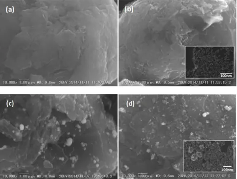
Figure 3. SEM images of (a) graphite, (b) cG, (c) Sn/G and (d) Sn/cG.
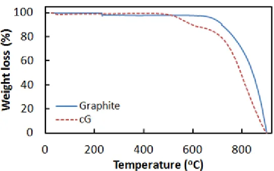
Fig. 2 shows TGA curves of the graphite and cG as the substrate materials. The graphite substrate showed significant weight loss at 675 oC due to combustion [27]. In contrast, the cG showed a two-step weight loss in the broad temperature range of 450 - 675 oC. It is presumed that the amorphous carbon and graphitic carbon burns at different temperatures in air [28]. The amount of amorphous carbon in cG is ~10.0 wt.%, judging from the TGA result.
Figure 4. EDS mapping of (a) Sn/G and (b) Sn/cG
[image:7.596.59.541.75.261.2]Elemental mapping for Sn shows uniform distribution on graphite or cG in Fig. 4, and that Sn NPs are better distributed on cG, which is in agreement with Fig. 3.
Figure 5. XRD patterns of graphite, cG, Sn/G and Sn/cG active materials
[image:7.596.185.415.383.528.2]
results show that the carbon-coating on graphite produce an active material with smaller particle size and better dispersed Sn on the substrate.
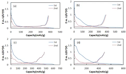
Fig. 6 shows the first and second cycles of charge-discharge for the active materials. Graphite showed discharge capacities of 370 and 375 mAh/g for the first and second cycles, which are close to the theoretical capacity. In comparison, cG showed slightly increased capacities of 383 and 390 mAh/g because the amorphous carbon coating could accept a small amount of Li+ ion [30]. In contrast, when Sn NPs were deposited on graphite or cG, the discharge capacities were significantly increased. Sn/G and Sn/cG showed 478/477 and 496/497 mAh/g of discharge capacities for the first and second cycles, which were ~26 and 30% of increased values, respectively. Sn-deposited materials were showing another plateau around 0.5 V, comparing with graphite.
Figure 6. Charge-discharge polarization curves of (a) graphite, (b) cG, (c) Sn/G and (d) Sn/cG electrodes at 0.1 C rate in 1.0 M LiPF6/EC+DMC(1:1 vol.%) electrolyte
[image:8.596.54.538.269.555.2]
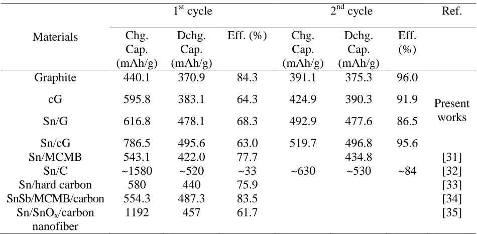
Table 3. Capacities and efficiencies of active materials at 1st and 2nd cycles
Materials
1st cycle 2nd cycle Ref.
Chg. Cap. (mAh/g) Dchg. Cap. (mAh/g)
Eff. (%) Chg. Cap. (mAh/g) Dchg. Cap. (mAh/g) Eff. (%)
Graphite 440.1 370.9 84.3 391.1 375.3 96.0
Present works
cG 595.8 383.1 64.3 424.9 390.3 91.9
Sn/G 616.8 478.1 68.3 492.9 477.6 86.5
Sn/cG 786.5 495.6 63.0 519.7 496.8 95.6
Sn/MCMB 543.1 422.0 77.7 434.8 [31]
Sn/C ~1580 ~520 ~33 ~630 ~530 ~84 [32]
Sn/hard carbon 580 440 75.9 [33]
SnSb/MCMB/carbon 554.3 487.3 83.5 [34]
Sn/SnOx/carbon
nanofiber
1192 457 61.7 [35]
dQ/dV plots in Fig. 7 shows clear evidence of intercalation/deintercalation or alloying of Li+ ion with graphite and Sn, respectively. Graphite showed typical peaks for the intercalation/deintercalation between graphene layers [36,37]. cG had another tiny peak around 0.77 V, which was attributed to greater electrolyte decomposition on porous carbon layer [38]. Electrochemical alloying of Sn with Li has several potential plateaus around 0.38, 0.42, 0.45, 0.53, and 0.66 V for forming Li3.5-4.4Sn, Li2.6-3.5Sn, Li2.3-2.6Sn, Li0.7-2.3Sn, and Li0.4-0.7Sn, respectively [39,40]. Insets in Fig. 7
(c) and (d) show that Sn/G and Sn/cG had peaks around 0.44, 0.55 and 0.67 V for alloying with Li. These three peaks may be assigned to the formation of Li2.3-3.5Sn, Li0.7-2.3Sn, and Li0.4-0.7Sn. The peak
around 0.38 V, which was correlated to the formation of Li3.5-4.4Sn in the literature, was not found in
Figure 7. dQ/dV plots of (a) graphite, (b) cG, (c) Sn/G and (d) Sn/cG electrodes for 1st and 2nd cycles at 0.05 C rate.
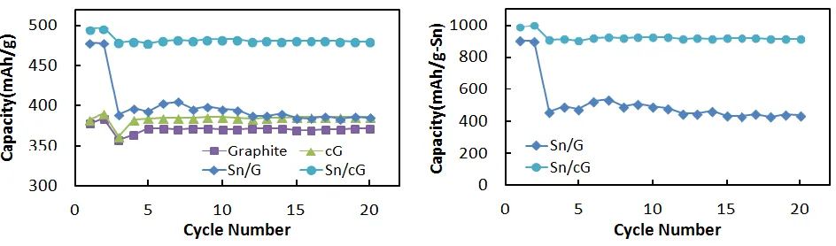
Figure 8. Specific discharge capacity of graphite, cG, Sn/G and Sn/cG electrodes per amount of (a) active material and (b) Sn as a function of cycle numbers. 0.05 C at first 2 cycles and 0.2C for the rest cycles
[image:10.596.62.531.74.214.2] [image:10.596.62.534.288.427.2]
chemical reduction process at room temperature without any heat-treatment [43,44] and physical deposition [45,46].
4. CONCLUSION
The Sn-deposited on graphite or carbon-coated graphite (cG) were successfully synthesized by a simple chemical reduction process at room temperature. The deposition of Sn NPs on substrates was confirmed by XRD, SEM, and ICP-AES. The distribution of Sn NPs on cG was more uniform and their sizes were smaller than those on graphite because of larger surface area. Sn/G and Sn/cG showed reversible capacities of 478.1 and 495.6 mAh/g at the first cycle, respectively, which were higher than that of graphite (370.9 mAh/g). Correspondingly, their efficiencies were 68.3 and 63.0%, which were lower than that of graphite (84.3%). However, the efficiency of Sn/cG at the second cycle recovered to 95.6%. Sn/cG showed very stable cyclability, and its capacity reached ~90 % of the theoretical capacity during continuous cycling at a rate of 0.2 C. The amorphous carbon layer on the graphite may enhance the adhesion of Sn NPs by compensating for the volumetric expansion during the alloying/dealloying with Li.
ACKNOWLEDGEMENT
This research was supported by the Ministry of Trade, Industry & Energy (MOTIE), Korea Institute for Advancement of Technology (KIAT) through the Encouragement Program for The Industries of Economic Cooperation Region.
References
1. Z. X. Shu, R. S. Mcmillian, J. J. Murray and I. J. Davidson, J. Electrochem. Soc., 143 (1996) 2230. 2. G. Derrien, J. Hassoun, S. Panero and B. Scrosati, Adv. Mater., 19 (2007) 2336.
3. M. Armand and J.-M. Tarascon, Nature, 451 (2008) 652.
4. I. D. Scott, Y. S. Jung, A. S. Cavanagh, Y. Yan, A. C. Dillon, S. M. George and S.-H. Lee, Nano Lett., 11 (2011) 414.
5. A. R. Kamali and D. J. Fray, Rev. Adv. Mater. Sci., 27 (2011) 14.
6. W.-M. Zhang, J.-S. Hu, Y.-G. Guo, S.-F. Zheng, L.-S. Zhong, W.-G. Song and L.-J. Wan, Adv. Mater., 20 (2008) 1160.
7. B. Huang, Y-I. Jang, Y-M. Chiang and D. R. Sadoway, J. Appl. Electrochem., 28 (1998) 1365. 8. R. A. Leising, M. J. Pallazzo, E. S. Takeuchi and K. J. Takeuchi, J. Electrochem. Soc., 148 (2001)
A838.
9. S.-K. Jeong, M. Inaba, R. Mogi, Y. Iriyama, T, Abe and Z. Ogumi, Langmuir, 17 (2001) 8281. 10.J. Shim and K. A. Striebel, J. Power Sources, 119-121 (2003) 934.
11.K. A. Striebel, A. Sierra, J. Shim, C.-W. Wang and A. M. Sastry, J. Power Sources, 134 (2004) 241.
12.B. Scrosati, Electrochim. Acta, 45 (2000) 2461.
13.G. X. Wang, J.-H. Ahn, M. J. Lindsay, L. Sun, D. H. Bradhurst, S. X. Dou and H. K. Liu, J. Power Sources, 97-98 (2001) 211.
15.T. Morishita, T. Hirabayashi, T. Okuni, N. Ota and M. Inagaki, J. Power Sources, 160 (2006) 638. 16.H. Lia and H. Zhou, Chem. Comm., 48 (2012) 1201.
17.G.A. Nazri and G. Pistoia, “Lithium batteries, Science and technology”, Kluwer Academic Publishers, 2004, p117
18.M. Watanabe, H. Sei and P. Stonehart, J. Electroanal. Chem., 261 (1989) 375. 19.M. Watanabe, S. Saegusa and P. Stonehart, Chem. Lett., 17 (1988) 1487. 20.I.-T. Kim, H.-K. Lee and J. Shim, J. Nanosci. Nanotech., 8 (2008) 5302.
21.I.-T. Kim, M. Choi, J.-C. An, H.-K. Lee and J. Shim, J. Nanosci. Nanotech., 10 (2010) 3643. 22.M. Choi, C. Han, I.-T. Kim, J.-C. An, J.-J. Lee, H.-K. Lee and J. Shim, J. Nanosci. Nanotech., 11
(2011) 838.
23.N. Ravet, Y. Chouinard, J.F. Magnan, S. Besner, M. Gauthier and M. Armand, J. Power Sources, 97-98 (2011) 503.
24.H. Wang, M. Yoshio, T. Abe and Z. Ogumi, J. Electrochem. Soc., 149 (2002) A499. 25.W.-S. Seo, T.-H. Kim, J.-S. Sung and K.-C. Song, Korean Chem. Eng. Res., 42 (2004) 78. 26.K. Torigoe, Y. Nakajima, and K. Esumi, J. Phys. Chem., 97 (1993) 8304.
27.J. Lee, S. Won, J. Shim, G. Park, H.-J. Sun and H.-K. Lee, Trans. Electr. Electron. Mater., 15 (2014) 193.
28.S. Osswald, G. Yushin, V. Mochalin, S. O. Kucheyev and Y. Gogotsi, J. Am. Chem. Soc., 128 (2006) 11635.
29.Y.-S. Park, H.J. Bang, S.-M. Oh, Y.-K. Sun and S.-M. Lee, J. Power Sources, 190 (2009) 553. 30.L Fransson, T. Eriksson, K. Edström, T. Gustafsson and J.O. Thomas, J. Power Sources, 101
(2001) 1.
31.M.-J. Denga, D.-C. Tsai, W.-H. Ho, C.-F. Li and F.-S. Shieu, Appl. Surf. Sci., 285 (2013) 180. 32.C. Nabais, R. Schneider, P. Willmann and D. Billaud, Energy Conv. Manag., 56 (2012) 32. 33.B. Guo, J. Shu, K. Tang, Y. Bai, Z. Wang and L. Chen, J. Power Sources, 177 (2008) 205. 34.J. Li, Q. Ru, S. Hu, D. Sun, B. Zhang and X. Hou, Electrochim. Acta, 113 (2013) 505. 35.L. Zou, L. Gan, R. Lv, M. Wang, Z.-h. Huang, F. Kang and W. Shen, Carbon, 49 (2011) 89. 36.T. Ohzuku, Y. Iwakoshi and K. Sawai, J. Electrochem. Soc., 140 (1993) 2490.
37.J. Shim and K.A. Striebel, J. Power Sources, 130 (2004) 247. 38.H. Wang and M. Yoshio, J. Power Sources, 93 (2001) 123.
39.J. Wang, I.D. Raistrick and R.A. Huggins, J. Electochem. Soc., 133 (1986) 457. 40.R.A. Huggins, J. Power Sources, 26 (1989) 109.
41.Y. Xu, Q. Liu, Y. Zhu, Y. Liu, A. Langrock, M.R. Zachariah and C. Wang, Nano Lett., 13 (2013) 470.
42.B. Luo, B. Wang, X. Li, Y. Jia, M. Liang and L. Zhi, Adv. Mater., 24 (2012) 3538. 43.G. Wang, Y.Q. Ma, Z.Y. Liu and J.N. Wu, Electrochim. Acta, 65 (2012) 275. 44.L. Liu, M. An, P. Yang and J. Zhang, Int. J. Electrochem. Sci., 10 (2015) 4461. 45.W. Liu, S. Zhang, N. Li, S. An, and J. Zheng, Int. J. Electrochem. Sci., 8 (2013) 347.
46.F. Nobili, M. Mancini, P.E. Stallworth, F. Crocec, S.G. Greenbaum and R. Marassia, J. Power Sources, 198 (2012) 243.