Power between Parallel Inverters
.
White Rose Research Online URL for this paper:
http://eprints.whiterose.ac.uk/142346/
Version: Published Version
Article:
Issa, W., Al-naemi, F., Konstantopoulos, G. orcid.org/0000-0003-3339-6921 et al. (2 more
authors) (2019) Stability Analysis and Control of a Microgrid against Circulating Power
between Parallel Inverters. Energy Procedia, 157. pp. 1061-1070. ISSN 1876-6102
https://doi.org/10.1016/j.egypro.2018.11.273
[email protected] https://eprints.whiterose.ac.uk/ Reuse
This article is distributed under the terms of the Creative Commons Attribution-NonCommercial-NoDerivs (CC BY-NC-ND) licence. This licence only allows you to download this work and share it with others as long as you credit the authors, but you can’t change the article in any way or use it commercially. More
information and the full terms of the licence here: https://creativecommons.org/licenses/
Takedown
If you consider content in White Rose Research Online to be in breach of UK law, please notify us by
ScienceDirect
Available online at www.sciencedirect.com
www.elsevier.com/locate/procedia
ć
Energy Procedia 157 (2019) 1061–1070
1876-6102 © 2019 The Authors. Published by Elsevier Ltd.
This is an open access article under the CC BY-NC-ND license (https://creativecommons.org/licenses/by-nc-nd/4.0/)
Selection and peer-review under responsibility of the scientiic committee of Technologies and Materials for Renewable Energy, Environment and Sustainability, TMREES18.
10.1016/j.egypro.2018.11.273
© 2019 The Authors. Published by Elsevier Ltd.
This is an open access article under the CC BY-NC-ND license (https://creativecommons.org/licenses/by-nc-nd/4.0/)
Selection and peer-review under responsibility of the scientiic committee of Technologies and Materials for Renewable Energy, Environment and Sustainability, TMREES18.
S
D
Keywords: microgrid; dc voltage, droop control. circulating power
* Walid Issa.
E-mail address: [email protected]
S
D
Technologies and Materials for Renewable Energy, Environment and Sustainability, TMREES18,
19
–
21 September 2018, Athens, Greece
Stability Analysis and Control of a Microgrid against Circulating
Power between Parallel Inverters
Walid Issa
a*, Faris Al-naemi
a, George Konstantopoulos
b, Sulieman Sharkh
cand
Mohammad Abusara
daSheffield Hallam University, Sheffield, UK b University of Sheffield, Sheffield, UK cSouthampton University, Southampton,UK
dExeter University, Penryn, UK
Abstract
In grid-connected mode, the grid normally absorbs all the power generated by each inverter in a microgrid. Droop control-based microgrid power management employs the frequency as a wireless communication to determine the power outage. However, in the cases of grid loss, each inverter should receive, from a supervisory controller, new settings of the output power suitable to the microgrid load. Because of the supervisory controllers are slower than the droop control loops, this might produce unstable dynamics caused by the excess generated power circulating between the inverters if the microgrid load is low. This case degrades the microgrid stability leading the DC link voltage of each inverter to rise to trip point. In this paper, a PD voltage control loop is proposed to stabilize the system and minimize the circulating power so providing more time for the supervisory control to respond
without tripping any inverter. A detailed small signal model is developed and stability analysis is performed to tune the controller’s
1.Introduction
In a grid-connected microgrid, the dynamics of parallel inverters are dictated by the stiff grid and the parameters of the local controllers. The stiff grid voltage provides decoupling between the dynamics of the inverters. The voltage at
the point of common coupling (PCC) can be used as a reference for all inverters’ dynamic calculations. However, in
island mode operation, the study of the dynamics of parallel inverters becomes more complicated as the voltage at the
point of common coupling (PCC) becomes dependent on the inverter’s power outputs and local loads.
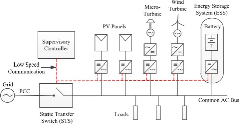
The majority of microgrid control structures reported in the literature are based on the droop control [1]–[5], which eliminates the need for communications between the inverters. However, a slow communication link is required between each inverter and a microgrid supervisory controller, Fig. 1, for setting some parameters of each unit. In order to study the stability of a microgrid in island mode, many researchers have developed mathematical models to describe the dynamics of the system. Pogaku et al. [6] has presented a systematic approach based on DQ frame to model an inverter-based microgrid containing multi inverters with the network and loads elements. Md et al. [7] used the same model but added PLL states for more accurate results especially for the reactive power steady states. Another model has been developed in [8] for multi islanded inverters based on the abc frame and it was used to evaluate the system stability against communication time delay. However, in all these models, the DC link voltage state for each inverter has not been included in the model and the effect of unintentional islanding on the stability of the DC link voltage has not been discussed. The DC link voltage was included in the small signal model reported by the authors in [9] but the model was only for two parallel inverters. In [6], the inner voltage and current controller loops were included in the model but it was concluded that the outer power sharing loop dominates the effect on stability. In addition, in [10], Iyer et al. assumed that the dynamics of the inner voltage and current loops can be neglected as their bandwidth are much higher than the outer droop controller loop due to the low pass filter used to average the active and reactive powers. Circulating power has been also addressed in [11] and [12] but non discussed the impact on the DC link voltage states.
In this paper, the impact on the DC link voltages in cases of circulating power flow, in particular, during the mains loss will be discussed and the stability of the microgrid will be assessed using the developed small signal models. Furthermore, a controller will be proposed to immune the microgrid stability. The small signal model is validated by simulation using a detailed model built in Matlab/Simulink.
PV Panels
Wind Turbine
Static Transfer Switch (STS) Grid
Loads PCC
Common AC Bus
Micro-Turbine
Supervisory Controller Low Speed Communication
Battery Energy Storage
[image:3.544.151.389.446.573.2]System (ESS)
Fig. 1. Microgrid Structure
2.System modeling
Walid Issa et al. / Energy Procedia 157 (2019) 1061–1070 1063
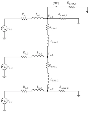
Fig. 2 The microgrid simulation model of three parallel inverters with two distribution lines and three loads
Eventually, the full microgrid model is then obtained as below where the states are .
. . . .
. . . .
. . . .
INV INV N io INVc INV N iLine INV N iLoad
mg NET INV com NETv N io INVc NET NETv N iLine NETv N iLoad
Load INV com Loadv N io INVc Loadv N iLine Load Loadv N iLoad
A B R C C B R C B R C
A B C B R C C A B R C B R C
B C B R C C B R C A B R C
+
= + +
+ +
(1)
All definition of these variables and states are as in [13].
3.Model evaluation
The small signal model in (1) is linearized around stable operating points. These points can be calculated by
two methods. One method is to set the nonlinear state equations to zero. Another approach is to simulate the model in
Matlab to determine the numerical solutions. Here, the second approach is adopted. Thereafter, the linearized model
has been compared with a three phase detailed model built in Matlab/Simulink using SimPowerSystem library with
the same parameters in Table 1. The first part of testing is to disturb the system by exciting it with a 3.8kW step
change. This is realized by closing the switch SW1 and engaging Load 3.
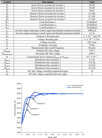
Fig. 3 shows the average active power output responses of the three inverters. The responses of both models are in good agreement, which reveals quite accurate transient expectations from the small signal model. Fig. 4 shows
,1
o
V
,1
o
R Lo,1 RLoad,1
,1
Line
R
,1
Line
L
,2
o
R Lo,2
,2
Line
R
,2
Line
L
,1
n
V
,2
n
V
,2
o
V
,3
o
R Lo,3 RLoad,2
,3
n
V
,3
o
V
,3
Load
R
1
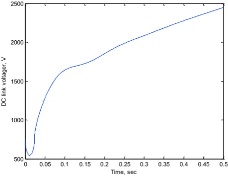
the active power responses of the three inverters if the set-points are ( ) and the load is 13.1 kW (without Load 3). The small signal model is again in a very good agreement with the detailed model. The third inverter is importing power which increases the voltage across the DC link capacitor. Fig. 5 shows how the DC link voltage of the third inverter is rising which will cause the inverter to trip unless a controller is used.
Table 1. Simulation Parameters of a three phase microgrid system
Symbol Description Value
Active Power set-point for inverter 1 20 kW Active Power set-point for inverter 2 10 kW Active Power set-point for inverter 3 0 kW Reactive Power set-point for inverter 1 0 VAR Reactive Power set-point for inverter 2 0 VAR Reactive Power set-point for inverter 3 0 VAR Load Resistance 1 25 Ω/phase Load Resistance 2 20 Ω/phase Load Resistance 3 38 Ω/phase Inverter output inductance (small signal and detailed simulation model) 2000 µH
Inverter output resistance (small signal and detailed simulation model) 0.1 Ω Frequency drooping gain rad/s/W
Voltage drooping gain V/Var Voltage set point 220 Vrms Frequency set point 50 Hz Measurement filter cutoff frequency 30 rad/s
Nominal DC link voltage 750 V Maximum DC link voltage 1200 V Linearization factor relating to
Distribution line reactance 1 0.1 Ω Distribution line resistance 1 0.23 Ω Distribution line reactance 2 0.58 Ω Distribution line resistance 2 0.35 Ω DC link voltage controller proportional gain 30
DC link voltage controller derivative gain 1
I I
S S M D M
I
[image:5.544.93.452.140.624.2]Walid Issa et al. / Energy Procedia 157 (2019) 1061–1070 1065
I I
S S M D M
[image:6.544.156.381.73.262.2]I
Fig. 4 Active power output of the three inverters under different power set-points (small signal model and detailed model)
0 0.05 0.1 0.15 0.2 0.25 0.3 0.35 0.4 0.45 0.5
500 1000 1500 2000 2500
Time, sec
D
C
l
in
k
v
o
lt
a
g
e
r,
V
Fig. 5 DC link voltage response of the third inverter
4.Proposed DC link voltage controller
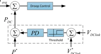
In this section, a PD controller will be proposed and studied for the multi-inverter model developed in previous sections. The proposed controller is shown in Fig. 6. It employs P and D terms to emphasize the generality of the modelling technique and to demonstrate that the derivative term also enhances the overshoot and settling time of the system response. The derivative term produces fast action corresponding to any disturbance. Thus, the D term allows for fast response to compensate the output variations in the DC voltage.
4.1.DC link voltage controller modelling
[image:6.544.151.381.312.489.2]* *
( . )( )
DC p d DClink DClink
P = −P + k +s k V −V (2)
By perturbing it around the equilibrium points we obtain,
( . ).
DC p d DClink
P k s k V
= + (3)
After rearranging, the controller for any inverter is calculated as,
1 2 3 2 3 . . [ ] .[0 ]. .[ ]
DC DC1 DClink DC inv
DC p
DC DC DC
DC d DCv P
DC d DCi
P C V C x
where
C k
C C C
C k B C
C k B
= + = = = = (4)
To insert this controller state equation into the model (1), the state of the phase angle has to change as,
. p( DC1. DClink DC. inv)
s = −
m +P C V +C x (5)Then the inverter model matrix will be as,
2
3'
, 2 3 2 2
1 2
. .
.
0 0
. .
p DC p DC
P Pv Pv Pi
inv i
Z P Z Tv Z
m C m C
A B C B
A
B C B C A
+ − − = + (6)
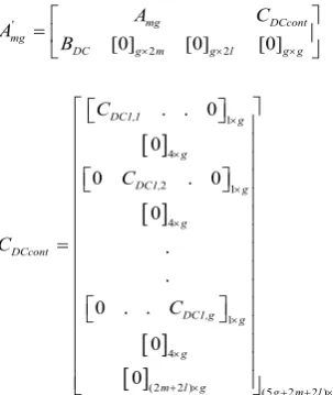
Consequently, the completed system with the DC voltage controller is derived as,
' 2 2 1 4 2 1 4 1 4(2 2 ) (5 2 2 )
[0] [0] [0]
. . 0
0
0 . 0
0
. .
0 . .
0
0
mg DCcont
mg
DC g m g l g g
DC1,1 g g DC1, g g DCcont DC1,g g g
m l g g m l g
A C A B C C C C + + + = = (7)
4.2.Analysis and simulation results
[image:7.544.151.303.398.578.2]The same detailed model of three inverters in island mode, that has been utilized to validate the small signal model, is used to justify the performance of the proposed controller and the prediction of the developed small signal model. Fig. 7 illustrates a zoomed version of the root locus of the microgrid model as the high frequency modes have less
Walid Issa et al. / Energy Procedia 157 (2019) 1061–1070 1067
the proportional gain varies as . As is seen, increasing shifts the complex poles to be dominant and
makes the system less damped toward instability if . The locus in Fig. 8 is developed as the parameters of the
PD controller vary. Fig. 8a depicts the poles evaluation as and in Fig. 8b as
. The arrows show the increasing trend. It is clear that the system is stable for the specified values range of that is wider than the case in Fig. 7. Furthermore, the derivative gain existence introduces more damping to the
system as the real poles dominate. In the other hand, by increasing , the system becomes unstable. The
[image:8.544.189.357.187.277.2]Matlab/Simulink simulation adopted the values of as they give a damping ration of 0.3.
Fig. 6 Proposed PD DC link voltage controller
Fig. 7 Root locus of the entire system with DC voltage controller when
D C
PD
DC P avg P
* P
DClink V
* DClink V T
-500 -400 -300 -200 -100 0 100 200 -500
-400 -300 -200 -100 0 100 200 300 400 500
-40 -30 -20 -10 0 10 20
[image:8.544.125.427.319.508.2]Fig. 8 Root locus of the entire system with DC voltage controller when (a) (b)
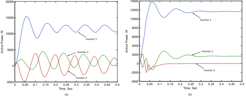
Fig. 9a shows the active power response of the three inverters when initially run in island mode with power set-points
are as . The derivative term is zero , which makes the
system more oscillatory as expected. The calculated frequency from the response is 62.2 rad/s and corresponds to the
expectations from the rootlocus which is 68 rad/s. Fig. 9b shows the response when . In contrast
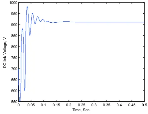
[image:9.544.64.470.404.566.2]with Fig. 4, the controller succeeds in mitigating the circulating power from the other inverters and consequently prevents the rise of the DC link voltage, Fig. 10, so decreasing the risk of tripping any inverter and presenting more damping compared with Fig. 9a. As shown, each inverter has a different transient oscillation frequency that is predicted by the rootlocus plot as well. The locus portends two frequencies as 55.13 and 307.5 rad/s and in Fig. 9b, the responses have two major frequencies of 54.16 and 306.5 rad/s, which reveals the validation of the developed model and the controller design criteria.
Fig. 9 The active power responses of the three inverters when initially run in island mode and (a) (b)
-500 -400 -300 -200 -100 0 100 200
-500 -400 -300 -200 -100 0 100 200 300 400 500
-500 -400 -300 -200 -100 0 100 200
-500 -400 -300 -200 -100 0 100 200 300 400 500 (a) (b)
0 0.05 0.1 0.15 0.2 0.25 0.3 0.35 0.4 0.45 0.5 -4000 -2000 0 2000 4000 6000 8000 10000 12000 14000 Time, Sec A c ti v e P o w e r, W
Walid Issa et al. / Energy Procedia 157 (2019) 1061–1070 1069
Fig. 10 DC link voltage responses of the third inverter when the PD controller is adopted
5.Conclusion
This paper investigated the transient power between paralleled inverters and its impact on the DC link voltage states in cases of mains loss. A PD controller to limit this circulating power has been proposed. The controller monitors the DC link voltage and in case the voltage rises above a specific limit, indicating power being imported, the controller adjusts the power set-point in proportion to the rise in the voltage. A small signal model of a microgrid has been developed to include the DC voltage states and used to design the controller. Simulation results confirmed the accuracy of the developed model and the validity of the design.
References
[1] M. A. Hossain, H. R. Pota, W. Issa, and M. J. Hossain, “Overview of AC microgrid controls with inverter
-interfaced generations,” Energies, vol. 10, no. 9, 2017.
[2] R. Al Badwawi, W. Issa, T. Mallick, and M. Abusara, “DC Microgrid Power Coordination Based on Fuzzy Logic Control,” in18th European Conference on Power Electronics and Applications, 2016, pp. 1–10. [3] W. R. Issa, A. H. E. Khateb, M. A. Abusara, and T. K. Mallick, “Control Strategy for Uninterrupted
Microgrid Mode Transfer During Unintentional Islanding Scenarios,” IEEE Trans. Ind. Electron., vol. 65, no. 6, pp. 4831–4839, 2018.
[4] R. AlBadwawi, W. Issa, M. Abusara, and M. Tapas, “Supervisory Control for Power Management of an
Islanded AC Microgrid Using Frequency Signalling-Based Fuzzy Logic Controller,” IEEE Trans. Sustain.
Energy, 2018.
[5] W. Issa, A. El Khateb, N. Anani, and M. Abusara, “Smooth mode transfer in AC microgrids during unintentional islanding,” in Energy Procedia, 2017, vol. 134.
[6] N. Pogaku, M. Prodanovic, and T. C. Green, “Modeling, Analysis and Testing of Autonomous Operation of an Inverter-Based Microgrid,” IEEE Trans. POWER Electron., vol. 22, no. 2, pp. 613–625, 2007.
[7] M. Rasheduzzaman, J. Mueller, and J. Kimball, “An Accurate Small-Signal Model of Inverter-Dominated Islanded Microgrids Using dq Reference Frame,” IEEE J. Emerg. Sel. Top. Power Electron., 2014.
[8] A. Kahrobaeian and Y. Abdel-Rady Ibrahim Mohamed, “Networked-Based Hybrid Distributed Power
Sharing and Control for Islanded Micro-Grid Systems,” IEEE Trans. POWER Electron., vol. 30, no. 2, pp. 0 0.05 0.1 0.15 0.2 0.25 0.3 0.35 0.4 0.45 0.5
550 600 650 700 750 800 850 900 950 1000
Time, Sec
D
C
l
in
k
V
o
lt
a
g
e
,
603–617, 2014.
[9] W. Issa, M. Abusara, and S. Sharkh, “Control of Transient Power during Unintentional Islanding of Microgrids,” IEEE Trans. Power Electron., vol. 30, no. 8, pp. 4573–4584, 2014.
[10] S. V Iyer, M. N. Belur, and M. C. Chandorkar, “A generalized computational method to determine stability
of a multi-inverter microgrid,” Power Electron. IEEE Trans., vol. 25, no. 9, pp. 2420–2432, 2010. [11] J. M. Guerrero, L. G. De Vicuna, J. Matas, M. Castilla, and J. Miret, “A wireless controller to enhance
dynamic performance of parallel inverters in distributed generation systems,” IEEE Trans. POWER Electron., vol. 19, no. 5, pp. 1205–1213, 2004.
[12] X. X. L. Chen C. Gong, and Y. Yan, “Circulating current’s characteristics analysis and the control strategy of parallel system based on double close loop controlled VSI,” Proc. IEEE PESC, pp. 4791–4797, 2004.
[13] W. Issa, M. Abusara, S. Sharkh, and T. Mallick, “A small signal model of an inverter-based microgrid