i
Power Management System (PMS)
JESSIE LIONG SHIH MAN
This Report Is Submitted In Partial Fulfillment of Requirements For The Bachelor Degree of Electronic Engineering (Computer Engineering)
Fakulti Kejuruteraan Elektronik dan Kejuruteraan Komputer Universiti Teknikal Malaysia Melaka
UNIVERSTI TEKNIKAL MALAYSIA MELAKA
FAKULTJ KEJURUTERAAN ELEKTRONIK DAN KEJURUTERAAN KOMPUTER BORANGPENGESAHANSTATUSLAPORAN
PROJEK SARJANA MUDA II
Tajuk Projek
POWER MANAGEMENT SYSTEM (PMS)
Sesi
Pengajian 11
4 I l 5
Saya JESSIE UONG SHIH MAN
mengaku membenarkan Laporan Projek Sarjana Muda ini disimpan di Perpustakaan dengan syarat-syarat kegunaan seperti berikut:
1. Laporan adalah hakmilik Universiti Teknikal Malaysia Melaka.
2. Perpustakaan dibenarkan membuat salinan untuk tujuan pengajian sahaja.
3. Perpustakaan dibenarkan membuat salinan laporan ini sebagai bahan pertukaran antara institusi
pengajian tinggi.
4. Sila tandakan ( >/ ) :
D
SULIT*D
TERHAO**0
TIDAK TERHAD*(Mengandungi maklumat yang berdarjah keselamatan atau
kepentingan Malaysia seperti yang termaktub di dalam AKT A RAHSIA RASMI 1972)
**(Mengandungi maklumat terhad yang telah ditentukan oleh organisasi/badan di mana penyelidikan dijalankan)
(TAN ENULIS)
.
~1
b/
d-0 t.(Tankh: ... ..
Ahamed Fayeez Bln Tuanl Ibrahim
Pensyarah
Fakulti Kejuruteraan Elektronik Dan. Kejuruteraan Komputef
Universiti Teknikal Malaysia Melaka (UTeM) Hang Tuah Jaya
76100 Durian Tunggal, Melaka
.
_) 4/
·
-z...o
Is-rankh: ... .
iii
"I hereby declare that this report is the result of my own work expect for quotes as
cited in the references."
Signature
Name
Date
\
~~
···~~~···
. JESSIE UONG SHIH MAN
...
iv
"I hereby declare that I have read this project report and in my own opinion this
project report is sufficient in terms of the scope and quality for the award of Bachelor
of Electronic Engineering (Computer Engineering) With Honours."
Signature
Name
Date
:
~N': .A~AM~l!..I:
A.YI;:~~.J?.
I;N.T.lJ.
AN'UJ?.MH~Mv
Specially..
To my beloved parents
And not forgetting to all friends
For their
vi
ACKNOWLEDGEMENTS
At first I appreciate Faculty of Electronic and Computer Engineering (FKEKK), Universiti Teknikal Malaysia Melaka (UTeM) for giving me a chance to design and implement my project.
I would like to thank all the people who are helping me and give me advice throughout the process in completing of my Final Year Project (FYP). I would never have been able to finish my project without the guidance of my supervisor, help from my friends, and support from my family.
Next, I would like to thank the person who gave me guidance and suggestion when I was lost in the junction to complete my FYP. He helps me a lot throughout the year in my FYP journey. He is a generous and a kind person who willing to space some precious time to meet me and gave advices to solve my FYP problem. I would like to thank him again, my FYP Supervisor Mr. Ahamed Fayeez bin Tuani Ibrahim. I am lucky able to do my FYP under his supervision.
viii
ABSTRAK
vii
ABSTRACT
ix
LIST OF CONTENT
CHAPTER TITLE PAGE
PROJECT TITLE i
CONFIRMATION REPORT STATUS ii
DECLARATION iii
SUPERVISOR CONFIRMATION iv
DEDICATION v
ACKNOWLEDGEMENT vi
ABSTRACT vii
ABSTRAK viii
TABLE OF CONTENTS ix
LIST OF TABLE xiii
LIST OF FIGURE xiv
LIST OF ABBREVIATION APPENDIX
xvii xix
1 INTRODUCTION 1
1.1 Problem Statement 2
1.2 Objectives 3
1.3 Scope of work 4
x
2 LITERATURE REVIEW 6
2.1 Literature Review on Journals 6
2.1.1 Touch Screen Based Home Automation Using Bluetooth with Raspberry Pi
6
2.1.2 Adaptive Home System Using Wireless Sensor Network and Multi Agent System
8
2.1.3 Access Control of Door and Home Security by Raspberry Pi Through Internet
9
2.1.4 Secured Smart Home Energy Monitoring System (SSHEMS) Using Raspberry Pi
11
2.1.5 Android Based Home Automation Using Raspberry Pi
12
2.1.6 Comparison table between journals 12
2.2 Conventional Technology 14
2.2.1 Raspberry Pi 14
2.2.2 Wireless 16
2.2.3 Arduino 17
2.2.4 Zigbee 18
2.2.5 Sensors 19
2.2.6 Relay Switch 19
2.2.7 Magnetic Door Lock 20
3 METHODOLOGY 21
3.1 General Flowchart 21
3.2 Simulation Method 23
3.2.1 Proteus 7 Professional Design Suite CAD Software
23
xi 3.2.1.2 ARES 7 Professional 24
3.3 Hardware Part 25
3.3.1 BC547 Transistor 25 3.3.2 SRD-05VDC-SL-C Relay 26 3.3.3 Raspberry Pi model B+ 27
3.3.4 LAN Cable 28
3.4 Software Part 29
3.4.1 MySQL 29
3.4.2 phpMyAdmin 30
3.4.3 HTML 31
3.4.4 PHP 31
3.4.5 JavaScript 32
4 RESULT AND DISCUSSION 33
4.1 Basic Concepts of PCS 33
4.2 Hardware Result 34
4.2.1 Overall Connectivity 34
4.2.2 Circuit Board 36
4.3 Software Result 37
4.3.1 Web Development in XAMPP Server 37 4.3.2 Raspberry Pi server part 48
4.4 Result of PMS 51
4.5 Result of Findings 52
4.6 Discussion 55
5 CONCLUSION AND FUTURE WORK 57
5.1 Conclusion 57
xii
REFERENCE
APPENDIX A APPENDIX B APPENDIX C
59
xiii
LIST OF TABLE
NO. TITLE PAGE
2.0 Comparison between Existing Technologies and System (journals) 12 2.1
4.0
Comparison between Different Raspberry Pi Models Explanation of Components
xiv
LIST OF FIGURE
NO. TITLE PAGE
1.0 Concept of Power Control System Using Raspberry Pi 2
1.1 Scope of work 4
2.0 Transmitter Section Hardware 7
2.1 Receiver Section Hardware 8
2.2 Diagram of Intelligent Home System 9
2.3 Main Project Outline 10
2.4 Prototype Design of Internet Controlled Door 10
2.5 Expression Tree 11
2.6 Raspberry Pi (Front) 14
2.7 Raspberry Pi (Back) 15
2.8 Wireless Technologies 17
2.9 Arduino Uno 18
2.10 TARANG Zigbee 18
2.11 Relay 20
2.12 Magnetic Door Lock 20
3.0 General Flowchart of Project Methodology 22
3.1 Simulation Flowchart Using Proteus Software 23
3.2 BC547 Transistor 25
3.3 SRD-05VDC-SL-C Relay 26
3.4 The Internal Structure of SPDT Relay 26
xv
3.6 Layout Model of Raspberry Pi B+ 28
3.7 MySQL Workbench 29
3.8 phpMyAdmin 30
3.9 HTML logo 31
3.10 PHP logo 32
3.11 JavaScript logo 32
4.0 Basic Concept of PCS 34
4.1 Flow Chart of Remote Switch from Internet 34
4.2 Coordinator and Circuit 35
4.3 Circuit Design Using ISIS Software 37
4.4 Circuit Design Using ARES Software 37
4.5 Login Page 38
4.6 4.7 4.8 4.9 4.10
User Login Successful User Login Failed Admin Login Successful Admin Page
GUI of Registration Form on Admin Page
38 39 39 40 40 4.11 4.12 4.13
Registration Database Table in phpMyAdmin Programming to Check Registered User Account has been Registered
41 42 43 4.14 4.15 4.16
GUI of Room Control in Admin Page
Programming Hyperlink to A Raspberry Pi Server
GUI of Booking Lecture Hall Application Form on User Page
43 44 45 4.17 4.18 4.19 4.20 4.21
Booking of Lecture Hall Application – Step 1 Booking of Lecture Hall Application – Step 2 Booking of Lecture Hall Application – Step 3 Booking of Lecture Hall Application – Final Step Interface.html file Programming
45 46 47 47 48
4.22 GUI Created by Interface file 48
4.23 app.js coding 51
xvi
4.25 Emeter with Raspberry Pi B+ 53
4.26 Energy Consumption by Raspberry Pi 54
4.27 Maglocks 54
xvii
LIST OF ABBREVIATION
AC - Alternate Current
API - Application Programming Interface COM - Common
DC - Direct Current
DPDT - Double Pole Double Throw DSL - Digital Subscriber Line GND - Ground
GPIO - General Pin Input Output GUI - Graphic User Interface
HTML - Hyper Text Markup Language LAN - Local Area Network
LCD - Liquid Crystal Display M2M - Mesh-to-Mesh
NO - Normally Open NC - Normally Closed PCB - Printed Circuit Board
PMS - Power Management System RF - Radio Frequency
xviii SPDT - Single Pole Double Throw
xix
LIST OF APPENDIX
NO TITLE PAGE
APPENDIX A RASPBERRY PI MODEL B+ 62
APPENDIX B BC 547 TRANSISTOR 65
1
CHAPTER 1
INTRODUCTION
Nowadays, the internet has become an integrated part of our life. It has become a common interface that many electronic devices were used in order to simplify the daily life of people. The internet is a powerful tool which has given people the ability to search, store and manage their own information. From the time of its introduction, the amount of people surfing the internet has increased dramatically and has become one of the major means of communication.
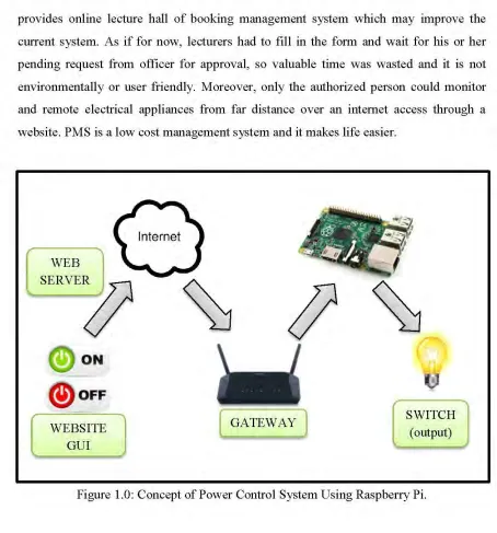
In order to make good use of the internet, online management system was invented. Power Management System (PMS) is a system that able to allow user to control any connected electrical appliances through the internet. By implementing this system in university, it could enhance current lecture hall management system by controlling faculty‟s electrical appliances such as an electromagnetic door lock, lighting and air-conditioner via online rather than manually. Thus, the university may no longer need to hire technicians to manage all the lecture halls because the electromagnetic door lock would be controlled by an authorized person via online system.
2
provides online lecture hall of booking management system which may improve the
current system. As if for now, lecturers had to fill in the form and wait for his or her
pending request from officer for approval, so valuable time was wasted and it is not
environmentally or user friendly. Moreover, only the authorized person could monitor
and remote electrical appliances from far distance over an internet access through a
website. PMS is a low cost management system and it makes life easier.
WEB
SERVE~
ON
@)
oFF
WEBSITE GUI
GATEWAY ) SWITCH
(output)
Figure 1.0: Concept of Power Control System Using Raspberry Pi.
1.1 Problem Statement
Currently the management system of controlling lecture hall doors is quite
troublesome, the students and lecturers have to wait for technician to unlock the door in
the early morning while the worker is late on duty. Besides that, it is wasting of
[image:21.612.97.551.61.548.2]3 ensure all electrical appliances are turned off and locked the door one by one every day after class session. So, it is actually a time wasting and unsystematic.
Furthermore, the technician has to work overtime if there are any extra activities that would be held in the lecture hall during the night, such as class replacement or there is a test conducted. Not only that, the university has to extra pay for the technician to work overtime, it is also very insecure if he has emerged and need to leave the campus earlier, he probably just leave the door unlocked until the next morning. This might cause vandalism in the lecture hall. Moreover, the current booking of lecture hall system is in manual, the lecturers have to fill in the form and need to wait for pending request from officer to be approved which may take time for days to wait upon approval. So, it is also wasting of valuable time and not environmentally friendly.
Thus, in order to overcome this problem, this project is to develop a low-cost system which provides real-time management of the lecture hall electrical appliances through online. Besides that, it also consists of a website to ease lecturers for their lecture hall booking procedure.
1.2 Objectives
The main objectives of this project are:
To develop a system to control electrical appliances through online system.
To develop a proper system to manage the lecture hall.
To develop a low cost and energy saving lecture hall management system.
4
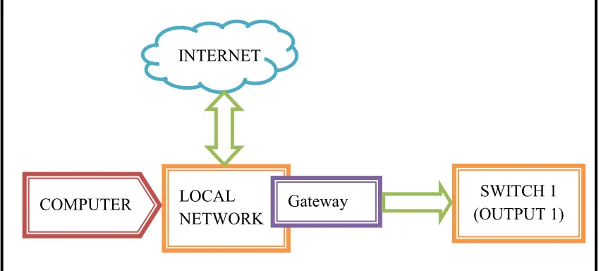
[image:23.612.115.541.114.306.2]1.3 Scope Of Work
Figure 1.1: Scope of work
The scope of work will be similar as the block diagram in Figure 1.1. This project will primarily focus on using the internet (local network) to control electrical appliances (switch). In order to do that, this project will target on one switch only. For online lecture hall booking system, this application is available only for registered staff or lecturers.
Next, only the authorised person can control the switch through a Graphic User Interface (GUI) button inside the website. On top of that, lecturers can‟t apply the booking system later than 5pm on the day he or she wants to use it. So for an emergency booking application, lecturers have to contact the authorised person personally. Lastly, this system application is only available in local system.
.
COMPUTER LOCAL
NETWORK Gateway INTERNET
5
1.4 Report Structure
This thesis consists of five chapters which contains the introduction, literature review, methodology, result and discussion as well as the last chapter is the conclusion and recommendation of the project.
CHAPTER 1 is the introduction of this project. In this chapter, the introduction, objective and problem statement of the project will be explained throughly. The concept behind the project and an overall overview of the project also will be discussed within this chapter.
CHAPTER 2 will mention about the literature review of the Raspberry Pi usage in managing power system by comparing other journal with the similar project system.
CHAPTER 3 is about the project methodologies of the project. This chapter will show the steps and the flow of the problem solving in such a specific method used to design and develop the Power Management System and also the other factors and characteristics that need to be focused on.
CHAPTER 4 will describe the expected result from this project and justify its performance to make sure it meets the objectives of this project.