THE EFFECT OF PLATE GEOMETRY ON FLOW AND HEAT TRANSFER ACROSS A PARALLEL PLATE HEAT EXCHANGER
CHO WEI YANG B041110217
Email: [email protected]
Projek Sarjana Muda
Supervisor: DR. FATIMAH AL-ZAHRAH BT. MOHD SA’AT
Faculty of Mechanical Engineering Universiti Teknikal Malaysia Melaka
SUPERVISOR DECLARATION
“I hereby declare that I have read this thesis and in my opinion this thesis is sufficient in terms of scope and quality for the award of the degree of
Bachelor of Mechanical Engineering (Automotive)”
Signature: ………..
THE EFFECT OF PLATE GEOMETRY ON FLOW AND HEAT TRANSFER ACROSS A PARALLEL PLATE HEAT EXCHANGER
CHO WEI YANG
This thesis is submitted as partial fulfilment of requirements for the award of Bachelor of Mechanical Engineering (Automotive) (Hons.)
Faculty of Mechanical Engineering Universiti Teknikal Malaysia Melaka
DECLARATION
“I hereby declare that the work in this thesis is my own except for summaries and quotations which have been duly acknowledged.”
Signature: ………. Author: CHO WEI YANG
iii
ACKNOWLEDGEMENT
First and foremost, I would like to express my sincere gratitude to my supervisor, Dr. Fatimah Al-Zahrah Mohd Sa’at, for guiding me throughout the entire PSM process. Without the advices and help from her, carrying out this study would be almost impossible. Therefore, I consider it as an honor to be able to work as a student under her.
I would also like to express my deepest gratitude to my university, Universiti Teknikal Malaysia Melaka (UTeM), and my faculty, Faculty of Mechanical Engineering, for granting me such great platform to learn and grow for the last four years.
Furthermore, I would like to thank all my friends who gave me support and encouragement throughout my process of learning here in UTeM. Without them, I may not be able to progress as smooth in my studies.
v
ABSTRACT
ABSTRAK
vii
TABLE OF CONTENTS
CHAPTER TITLE PAGE
DECLARATION ii
ACKNOWLEDGEMENT iv
ABSTRACT v
ABSTRAK vi
TABLE OF CONTENTS vii
LIST OF FIGURES x
LIST OF TABLES xii
LIST OF ABBREVIATION AND SYMBOL xiii
LIST OF APPENDIXES xv
CHAPTER 1 INTRODUCTION
1.1 Background 1
1.2 Problem Statement 3
1.3 Motivation of Study 4
1.4 Objectives 4
1.5 Scope 4
CHAPTER 2 LITERATURE REVIEW
2.1 Flow 6
2.2 Heat Transfer 10
2.3 Heat Exchanger 12
2.4 Thermoacoustics 14
2.6 Effect of Geometry of Parallel-Plates on Flow
and Heat Transfer 17
CHAPTER 3 METHODOLOGY
3.1 Pre-Processing 22
3.2 Solver Settings 26
3.3 Pre-Processing for Different Geometries 30
CHAPTER 4 RESULTS AND ANALYSIS
4.1 Validation 32
4.2 Vorticity Contours 34
4.2.1 Original Model 35
4.2.2 Case 1 36
4.2.3 Case 2 37
4.2.4 Case 3 38
4.3 Total Surface Heat Flux 39
4.3.1 Original Model 40
4.3.2 Case 1 42
4.3.3 Case 2 43
4.3.4 Case 3 45
CHAPTER 5 DISCUSSION
5.1 Comparison of Local Surface Heat Flux
Between All the Cases at Point A 47 5.2 Comparison of Local Surface Heat Flux
Between All the Cases at Point B 48 5.3 Comparison of Local Surface Heat Flux
Between All the Cases at Point C 49 5.4 Comparison of Average Total Surface Heat
Flux Over Time at Hot Heat Exchangers
ix
5.4 Vorticity Contours Comparison at the Edges
of All the Cases 51
5.5 Velocity Profile Comparison between All
the Cases 52
CHAPTER 6 CONCLUSION AND RECOMMENDATION 54
REFERENCES 55
LIST OF FIGURES
NO. TITLE PAGE
1.1 Illustration on position of heat exchangers and stack. 2 2.1 Illustration of laminar and turbulent flow. 7 2.2 Von Karman vortex (Cesareo de La Rosa Siqueira, 2005). 9 2.3 All three types of heat transfer process. 10 2.4 Illustration of double-pipe heat exchanger in parallel flow. 13 2.5 Illustration of double-pipe heat exchanger in cross flow. 13 2.6 PLIF image of heat transfer at the parallel-plates heat exchangers
from Jaworski and Piccolo (2012). 16 2.7 Illustration on the flow pattern at the end of sharp-edged plate. 20 2.8 Results from ANSYS Fluent 13 simulation on vortex generation
by Mohd Sa’at and Jaworski (2013). 21
3.1 Flow chart of this study. 22
3.2 Illustration of the computational domain and its dimensions. 23
3.3 Drawing of domain using ICEM. 24
3.4 Drawing of domain using ANSYS Workbench after creating surface. 25 3.5 Meshing of the domain after adjusting the sizing of the meshes. 25
3.6 FLUENT window. 26
3.7 Illustration of some important positions for calculation and validation
works. 28
xi
4.1 Changes of x-velocity of point M at different phases. 32
4.2 Grid sensitivity test. 34
4.3 Vorticity contours of original model simulation at different phases. 35 4.4 Illustration of flow over original model from phase 0 to 10. 35 4.5 Illustration of flow over original model from phase 11 to 20. 36 4.6 Vorticity contours of case 1 model simulation at different phases. 36 4.7 Illustration of flow over case 1 model from phase 0 to 10. 37 4.8 Vorticity contours of case 2 model simulation at different phases. 37 4.9 Illustration of flow over case 2 model from phase 0 to 10. 38 4.10 Vorticity contours of case 3 model simulation at different phases. 38 4.11 Illustration of flow over case 3 model from phase 0 to 10. 39
4.12 Location of point A, B and C. 39
LIST OF TABLES
NO. TITLE PAGE
3.1 Properties of several types of gas at temperature
of 300 K (Swift, 2001). 27
xiii
LIST OF ABBREVIATIONS AND SYMBOLS
Re = Reynolds number
ρ = Density
Vavg = Average velocity
D = Geometry characteristic length μ = Dynamic viscosity
ν = Kinematic viscosity
CFD = Computational Fluid Dynamics
𝑄̇ = Rate of heat transfer
k = Thermal conductivity A = Surface area
𝑑𝑇
𝑑𝑥 = Temperature gradient
h = Convection heat transfer coefficient Ts = Surface temperature
𝑇∞ = Surrounding temperature
σ = Stefan-Boltzmann constant ɛ = Emissivity of the surface
𝛿𝑘 = Thermal penetration depth
ω = Angular frequency
Cp = Constant pressure heat capacity per unit mass 𝛿𝑣 = Viscous penetration depth.
LIST OF ABBREVIATIONS AND SYMBOLS
yo = Half distance between parallel plates
l = Length of heat exchanger
PLIF = Planar Laser Induced Fluorescence PIV = Particle Image Velocimetry
xv
LIST OF APPENDIXES
NO. TITLE PAGE
CHAPTER 1
INTRODUCTION
1.1 BACKGROUND
When a flow is flowing past a blunt body or solid boundaries, there will be interactions between the flow and the solid bodies. In this study, the solid boundaries will be a pile of parallel-plates acting as heat exchangers. There will be formation of various flow patterns when a flow flows past the parallel-plates. Other than flow patterns, there is also interaction in terms of heat transfer since the parallel-plates will be acting as heat exchangers. The temperature difference around the plates region will cause the occurrence of heat transfer between the flow and the plates due to the temperature gradient. The focus of this research is to study how the changes in the plate geometry (shape or dimensions of parallel-plate) may disturb or affect the flow and heat transfer across a parallel-plate heat exchanger. In discussing the flow and heat transfer across a parallel-plate heat exchanger, the working medium used is very important too. Oscillatory flow which the flow will propagate forth and back will be used in this research.
2
significantly due to the back and forth movement. Oscillatory flow mixing technology can also be found widely in chemical and process engineering. Another application of oscillatory flow, which is also the focus of our research, is a thermoacoustic heat exchanger. This heat exchanger extracts and supplies heat obtained from the thermoacoustic system.
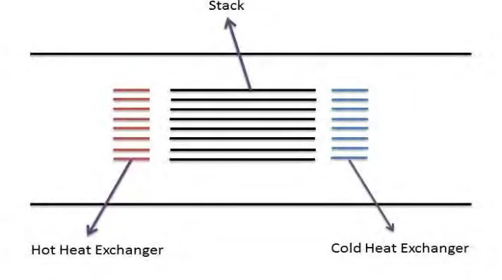
[image:19.612.159.515.322.521.2]The main working medium behind thermoacoustics is a type of flow called oscillatory flow. This flow is formed from sound waves with amplitudes high enough to transfer heat from one place to another. On the other hand, sufficiently high temperature gradient can also be used to create sound waves of high amplitudes. This flow plays an important role because the oscillatory flow will move back and forth expanding and contracting in order to do work.
Figure 1.1: Illustration on position of heat exchangers and stack.
of energy, the interaction between the flowing fluid and the solid surface of the stack may produce either cooling effect or power.
The heat exchangers at the ends of ‘stack’ are responsible to effectively remove heat from the system and provide cooling capacity to the refrigerated space that is attached to the system. On the other hand, if the heat exchangers provide a high enough temperature gradient to the fluid, such that allows the fluid particle to excite, power will be produced. The energy produced may then be harnessed for other useful application.
1.2 PROBLEM STATEMENT
4
1.3 MOTIVATION OF STUDY
Often the other parameters are taken into consideration when studies are carried out regarding the oscillatory flow or heat transfer near solid structures. Geometry and gap dimensions however get less attention as compared to other parameters. Considering the fact that changing geometry will affect the contact surface of the plate and also the possibility of creating disturbances to the flow, researches should be carried out more about this factor. The purpose of this study is to gain more information on the effect of geometry of the parallel-plates on the heat transfer and flow so that this concept appears attractive to the industry sooner.
1.4 OBJECTIVES
There are several objectives in completing the study. The objectives are to:
i) Study the thermoacoustic heat exchanger and to understand the working principle and knowledge related to it.
ii) Formulate simplified models for the purpose of comparison of flow and heat transfer between different geometries.
iii) Validate the model with available published work; experimental or theoretical data.
iv) Analyze the results and study the effect of parallel-plates geometry on the flow and heat transfer around the heat exchanger.
1.5 SCOPE
6
CHAPTER 2
LITERATURE REVIEW
2.1 FLOW
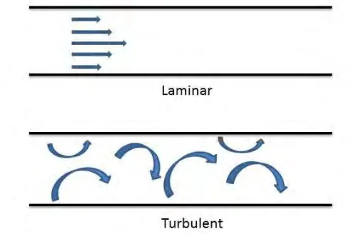
become maximum when the flow is fully turbulent. This will requires more input to overcome the large friction forces.
Figure 2.1: Illustration of laminar and turbulent flow.
The classification of the three phases mentioned earlier is made possible with the help of a dimensionless number, the Reynolds number. Reynolds numbers, Re, was discovered by Osborne Reynolds in 1880s. He found out that the flow regime or the order of the flow is highly dependent on the ratio of inertial forces to viscous forces in the fluid. Inertial force can be considered as the amount of force a fluid put up to resist any change in its motion. Viscous force can be explained as the shear force experienced by the flow when it flows past a solid body. In easier analogue, viscous force can be considered as frictional force. Reynolds number can be expressed as;
Re =
inertial forcesviscous forces=
𝜌𝑉𝑎𝑣𝑔𝐷𝜇 (2.1)
where ρ is the density of medium, Vavg is the average velocity of the flow, D is the
geometry characteristic length and μ is the dynamic viscosity of the medium. Reynolds number can also be expressed in terms of kinematic viscosity;