A Passive Biodegradable Implant for Subcutaneous
Soft-Tissue Trauma Monitoring
Jonathan M. Rigelsford, Senior Member, IEEE, Baraa F. Al-Azzawi,
Christopher James Davenport, and Peter Novodvorsky
Abstract—In-body medical devices can play an important role in clinical monitoring and diagnosis of diseases. Wireless devices implanted within a patient have to be physically small, and must overcome the challenges of having a little or no onboard electrical power and the highly attenuating electromagnetic propagation en-vironment which is the human body. In this paper, we investigate the use of biodegradable implant to monitor the healing of soft-tissue trauma and to allow early stage diagnosis of infection. The implantable tag is designed to degrade in a predetermined and con-trolled method, the stage of which can be measured from outside the body without the need for further surgical intervention. The speed of degradation of the tag depends on the temperature and acidity of the subcutaneous tissue in which the tag is implanted. We show that as the electrical length of the tag pattern increases due to degradation, the resonant frequency changes significantly, and this change in resonant frequency can be detected from outside the patient. Results are presented showing the tag’s performance at normal and oblique incidence, and techniques for miniaturizing and enhancing the tag’s response sensitivity are given. As the en-tire tag is biodegradable, there is no need for further postoperative surgery to remove it from the patient at the end of its useful life.
Index Terms—Biodegradable, implant, in-body devices, radio frequency identification (RFID).
I. INTRODUCTION
T
O achieve high-quality standards within the healthcare sec-tor, improved and robust health monitoring systems have become a necessity. Such systems can help to reduce the num-ber of specialist medical consultations and hospital admissions. Additionally, they can make the process of establishing medical diagnoses less error prone [1], [2]. Implantable medical devices are being used frequently in diagnosis and treatment of a variety of medical conditions [3]. They can also be used to monitor physiological parameters, such as heart rate, blood pressure and body temperature [2], or glucose levels in blood [4]. Commu-nication often occurs with an external reader is wireless in the frequency band 402 to 405 MHz (medical implant communica-tion service) [5].Manuscript received November 1, 2014; revised February 4, 2015; accepted March 20, 2015. Date of publication; date of current version. This work was par-tially funded by the University of Sheffield and the EPSRC E-Futures Doctoral Training Centre.
J. M. Rigelsford, B. F. Al-Azzawi, and C. J. Davenport are with the Depart-ment of Electronic and Electrical Engineering, University of Sheffield, Sheffield S1 3JD, U.K. (e-mail: j.m.rigelsford@sheffield.ac.uk; baraa.faiq@gmail.com; christopher.davenport@sheffield.ac.uk).
P. Novodvorsky is with the Department of Diabetes and Endocrinology, Royal Hallamshire Hospital, Sheffield S10 2JF, U.K. (e-mail: p.novodvorsky@ sheffield.ac.uk).
Color versions of one or more of the figures in this paper are available online at http://ieeexplore.ieee.org.
[image:1.594.331.522.180.364.2]Digital Object Identifier 10.1109/JBHI.2015.2417754
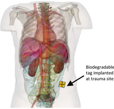
Fig. 1. Illustration of a patient with implanted tag (tag is not shown to scale).
Radio frequency identification (RFID) technology has gained a considerable importance in recent years. Its use is no longer restricted to tracking and positioning of patients but it has been used as a monitoring device for different processes inside the human body [6]. RFID tags can be embedded in other implanted devices, sutures, and prostheses to collect data or track chemi-cal or physichemi-cal changes in the surrounding environment [7], [8]. It has been suggested that RFID could also be used to mon-itor healing processes in soft-tissue injuries and to signal any abnormalities [9].
on excessive prescription of antibiotics, and help mitigate un-necessary additional surgery, which in itself can lead to further risk of infection and complications. The implanted RFID tag can be monitored from outside the patient using a measurement device similar to the hand held “wand” metal detectors used by airport security. Alternatively, the implant can be continuously monitored using a compact body worn antenna system.
Section II provides an overview of the background theory and the motivation behind this study, outlining why develop-ment of such a device is important. Section III briefly addresses biodegradable materials, which are suitable for the use in med-ical implants and which can be exploited in this study. The concept and the operation of the tag are discussed in Section IV, while Section V discusses simulated results and analysis, including the tag’s performance at oblique illumination angles. Section VI presents techniques for miniaturization and increas-ing the tag response sensitivity. Preliminary experimental results and validation are presented in Section VII, and discussions and conclusions are given in Section VIII.
II. BACKGROUND ANDMOTIVATION
Colorectal (bowel) cancer is the most commonly diagnosed cancer and the second most common cause of cancer deaths in Europe [10]. In 2008, there were 450 000 new cases of colorec-tal cancer, and 232 000 deaths caused by this condition within the World Health Organization European Region [11]. Due to location and nature of surgery required to remove this type of cancer, the risk of infection and complications to the wound site, deep within the lower abdomen, can be problematic to the pa-tient. Additionally, shrapnel wounds caused by military combat operations or terrorist attacks are another (and unfortunately far too common) cause of soft-tissue trauma. In the first Gulf War (1990–1991) 80% of penetrating wounds on British personnel were caused by fragments from explosive munitions, such as shells, grenades, and improvised explosive devices, rather than bullets. Beyond the damage caused by shrapnel to tissue and or-gans within the body, infection will result in further progressive tissue damage and represents a key risk factor for the patient’s recovery. Tissue healing may also be delayed by metal poison-ing from the shrapnel itself [12]. Data obtained from the Wound Data and Munitions Effectiveness Team database [12] show that although there is a 47% chance of the soft tissue being the primary injury site, less than 1% of these result in death. Con-versely, injuries to the abdomen (8%) and chest (4%) account for 9% and 24% of fatal injuries, respectively, [13]. Despite the high survival rate from the initial soft-tissue trauma, there is significant potential for long-term complications for a patient who is likely to survive.
Complications and postoperative infections of soft-tissue traumas deep within the body can be difficult to monitor using conventional techniques, such as X-rays or CT/MRI scanners, although the wound site can be marked using medical staples. As the range of currently available effective antibiotics dimin-ishes, treatment via prolonged or extensive doses of antibiotics becomes less feasible. Frequently, complications are only de-tected when the patient becomes acutely unwell, with localized swelling and redness or with fever and wounds weeping pus.
Inflammation can be defined as a nonspecific biological re-sponse of the human body to harmful stimuli, such as infection, radiation, and tissue damage [14]. It represents a nonspecific body defense mechanism in which a number of substances are released from damaged tissues. These further trigger various inflammatory cascades, leading to substantial changes in the surrounding area. Regardless of the cause, inflammatory re-sponse shares some common characteristics. Inflammation can be characterized by five key signs: heat, pain, redness, swelling [15], [16], and loss of function. It has been shown that injured tissues experience local acidosis—an increase in acidity level (defined by lower pH). This is explained mainly by the increase of lactic acid production as a result of anaerobic metabolism of infiltrated white cells (neutrophils), but also by production of fatty acid by-products of bacterial metabolism [17], [18]. Additionally, the intracellular pH of an activated neutrophil is very low, and this highly acidotic content gets released to the surrounding environment when neutrophils die [19].
Surgical site infection is a generic term which refers to any postoperative infections developed at the site of surgery [20]. Statistics have shown that about 4–5% of all surgical patients will suffer from the postoperative infection [20], [21]. They are one of the significant causes of morbidity for patients who have undergone a surgery [21], and it has been suggested that SSIs are responsible for about one third of the postsurgical mortality [20]. It has been reported that SSIs can occur at any point up to 30 after surgery [22]. Apart from the negative impact on the patient health, SSIs impose economic burdens on health services, with patients who suffer from SSIs requiring on average an additional 6.5 days in hospital. Generally, SSIs are treated with antibiotics [22], although excessive prescription of antibiotics has led to an increase in antibiotic resistant bacterial strains [20] and help mitigate unnecessary additional surgery, which in itself can lead to further risk of infection and complications.
Therefore, in this study, we consider the engineering chal-lenges that must be solved when designing a passive biodegrad-able implant for subcutaneous soft-tissue trauma monitoring. Having examined how the two key signs associated with infec-tion of soft tissues, namely increase in temperature and acidity can influence degradation behavior of biodegradable polymers, we intend to exploit this in our design of a passive biodegradable tag, which can be used for the early stage detection of infection. As the tag degrades in a predetermined and controlled man-ner, changes in its electromagnetic response can be monitored from outside the patient. Acceleration in the rate of degradation caused by an increase in local temperature and acidity are indica-tive of infection. This acceleration is beyond the normal degra-dation which is influenced by the choice of biodegradable mate-rials, the location of the tag and the time since it was implanted.
III. BIODEGRADABLEMATERIALS FORMEDICALIMPLANTS
which converts implanted materials into simpler compositions, and finally into basic chemical elements [24]. This study consid-ers two forms of biodegradable materials: polymconsid-ers and metal-lic alloys. Choosing among them depends on how they will be applied [25]. With biodegradable materials there is no need for human intervention to remove them, as they will eventu-ally be absorbed by the body. Several types of biodegradable polymers are available such as polylactic acid (PLA), poly-caprolactone (PCL), and polylactide-coglycolide. Among them, PLA has gained special interests due to its ease of fabrication and to some unique properties. Degradation of polymers oc-curs either biotically or abiotically. Biotic degradation refers to changes that occur by the help of biological environment, such as microorganisms or enzymes. Abiotic agents are mainly en-vironmental factors, such as mechanical forces, light, heat, and chemicals. Biodegradable polymers are used in several applica-tions in medicine, pharmaceutical, and biomedicine. Examples of them are sutures, drug delivery carriers, and tissue or organ repairing [26]. Some magnesium alloys have been developed to be biodegradable [27]. They are used in different medical appli-cations, such as in orthopedic implants as pins and screws, and as stents in cardiovascular procedures. The advantage of such alloys is that they can be dissolved in the body completely with-out toxic remnants. It has been shown that metallic alloys can degrade much faster than the polymers in the same biological environment [23].
Degradation time of plastic polyesters in the human body depends on many factors ranging from the surface area and to-tal size of the substrate, to the material composition itself and the acidity surrounding the implanted material. Research into this area is well documented [28]–[31]. In this study, we focus on PLA and PGA as suitable biodegradable substrates for the manufacture of our passive implant. The difference in degra-dation between PLA-PCL and PGA-PCL composite fibres in both water and phosphate buffered saline are presented in [32]. This study shows that PGA composite degrades much quicker than the PLA, and copolymerization of the two can be used to control the speed of degradation finely. Furthermore, the effect of acidity on the degradation of PLA brushes over the course of a few weeks has been investigated [33], where results show that the neutral or slightly alkaline solutions result in the fastest breakup of PLA, whereas slightly acidic solutions severely re-duce the rate of degradation. Investigation of the degradation of the PLA sheets used in our experiments are currently be-ing conducted to establish whether similar degradation will occur.
IV. PASSIVEDEGRADABLETAGDESIGN
[image:3.594.319.532.68.207.2]This section provides the design and analysis of a passive tag which changes its frequency response based on degradation state. It is proposed that when the tag is illuminated by a RF transmission from outside the body, the degradation state, and ultimately the state of infection, can be assessed. This study provides an analysis of several key interest areas, such as the effect of degradation state, angle of interrogation, and insertion into a fat layer, on the tag’s frequency response.
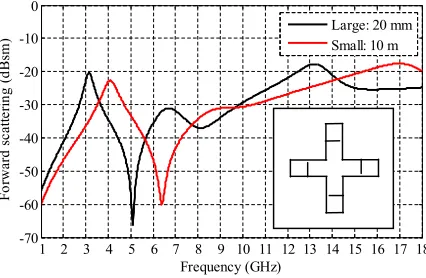
Fig. 2. Copolarized frequency response of a degradable cross-shaped tag, of diameters 20 (large) and 10 mm (small).
A. Passive Structure Resonance
The design process of passive structures involves investiga-tion of several parameters, such as shape, size, and substrate choice. There are two main RF considerations in developing such structures for use as implantable devices. First, it is essen-tial to ensure that the device resonates in a frequency band that is easy to measure. Second, the frequency response must change based on a progressive degradation.
In general, the frequency response of a frequency selective surface (FSS) is related to its dimensions [34]. A similar prin-ciple can be applied to these structures. It is thus proposed that degradation involving changing the length of the biodegradable implant would be the best choice. A basic example explaining the possible changes in harmonic frequency response due to re-ducing the size of the tag is shown in Fig. 2, whereby a large cross with a diameter of 20 mm produces a resonance at 3 GHz, while a smaller 10-mm diameter cross produces a resonance at 4 GHz. By simply alternating the size of the cross, a different RF response can be measured.
B. Tag Structure and Degradation
Based on initial degradation simulations, a cross shape with several break points was designed, as shown in Fig. 3. The tag has track widths, w= 0.15 mm. Each arm length L was 6.25 mm, having an arm interconnect length A of 0.55 mm. The subsectioned lengths were arbitrarily chosen asB = 2.15mm, C= 0.98mm,D= 0.81mm,E= 0.67mm,F = 0.68mm, andG= 0.72mm.
Fig. 3. (a) Proposed tag structure with closer view of tag dimensions. (b) Illustration of miniaturized break points to ensure sequential degradation.
interconnects within each arm section (see labeled 1, 2, 3, 4, and 5 in Fig. 3) can be designed to degrade in a predetermined sequence by changing the width and thickness of the conductive track. As each interconnect degrades in turn, the path length of the inner cross increases and, thereby, decreasing the resonant frequency of the tag. Realistically, the degradation would be achieved by designing small break points at the ends of each interconnect [see Fig. 3(b)], using thick or wider track lines which take longer to degrade, rather than relying on the entire interconnect to degrade. Such techniques have been previously considered in [35] and [36].
In our simulation work, the structure of the tag is gradually changed to understand how the harmonic response changes and whether or not a measurable difference can be seen.
V. SIMULATIONRESULTS ANDANALYSIS
Electromagnetic performance analysis of the degradable tag has been simulated using CST Microwave Studio. The tag was illuminated by a linearly polarized plane wave signal. The fre-quency response of the tag was obtained using two perpendicular radar cross section (RCS) probes, enabling co- and cross-polar measurements to be performed. Both RCS probes were located 100 mm from the tag.
Simulations have been performed from 1 to 18 GHz using the transient (time domain) solver was used with hexahedral mesh-ing, with care being taken to ensure features were adequately meshed and that scattering from the solver mesh did not produce false responses in the results. The boundary conditions were set to open (add space).
The tag structure was modeled using a perfect electrical con-ductor material which is representative of metallic materials. The cross was positioned on a PLA substrate.
A. Initial Simulation
[image:4.594.323.528.69.177.2]Simulation results showing the gradual degradation of the tag are shown in Fig. 5. It is evident that as the tag degrades the
Fig. 4. Simulation model of the degradable tag and coordinate system.
Fig. 5. Copolarized response of the tag at different degradation levels.
harmonic frequency changes considerably. The most noticeable effects are the reduction of the harmonic null, which ranges from 9.6 GHz for the complete tag to 6.2 GHz for degradation state 5.
B. Tag Geometry and RF Response
A primary objective of this study is to develop a degradable tag, which has a unique RF signature which can be used to determine the tag’s state of degradation. If the tag is implanted in a patient, monitoring this degradation on a regular basis will allow for early detection of infection as this increases the rate of degradation due to the local increase in temperature and acidity as described in Section II. It is, therefore, not only desirable to be able to detect the series of unique RF signatures as the tag degrades, but to be able to predict the degradation status at a given time after being implanted. The break points in the passive tag can be positioned to provide predetermined frequencies at which the peaks and nulls in the frequency response will occur. These frequencies can be empirically determined by analysis of the simulated tag responses. For the tag geometry shown in Fig 3, the frequency of the resonance peak can be expressed as
Fp eak(x) =F(0)−0.345(x−1) (1)
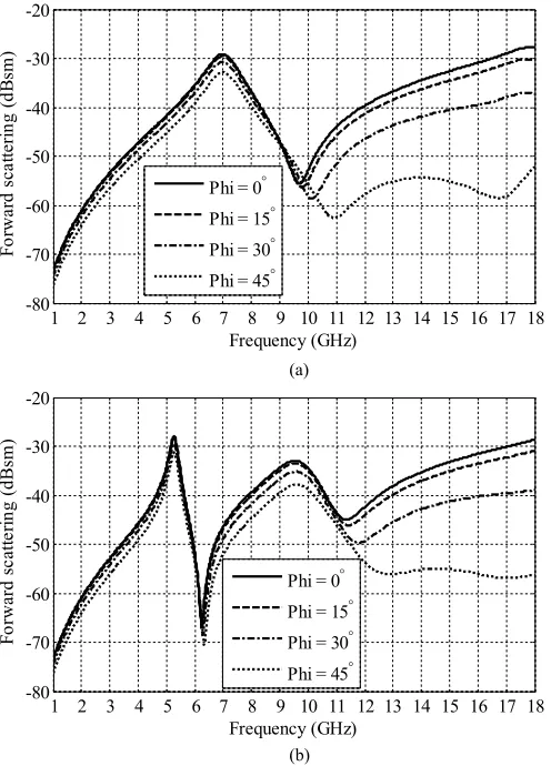
[image:4.594.308.553.221.378.2]Fig. 6. Copolarized response of the tag for different oblique azimuth (φ) angles for (a) the full tag and (b) the fully degraded tag.
Similarly, the position of the first null at a higher frequency than the resonance is located at
Fnull(x) =Fp eak(x)(1.385−0.04(x−1)). (2)
C. Oblique Incidence Performance
Once implanted and fixed within the patient’s body, there is no guarantee that the illumination of the transmitter will be at normal incidence to the tag. The absolute position and orienta-tion of the tag will vary from patient to patient. Therefore, the performance of the tag at several angles of incidence in both the elevation (θ) and azimuth (φ) are investigated (see Fig. 4) when illuminated by a plane wave polarized parallel to the x-axis. The response for a complete tag over various angles of incidence is compared to a fully degraded one.
[image:5.594.41.289.67.412.2]Fig. 6 compares the copolarized response of the tag for dif-ferent oblique azimuth (φ) angles for (a) the full tag and (b) the fully degraded tag. This can be compared to Fig. 7 which com-pares the copolarized response of the tag for different oblique elevation (θ) angles for (a) the full tag and (b) the fully degraded tag. In both cases, the results show good levels of angular stabil-ity with no change in resonant frequency and minimal change to the peak amplitude. However, the relative amplitude of the
Fig. 7. Copolarized response of the tag for different oblique elevation (θ) angles for (a) the full tag and (b) the fully degraded tag.
response at higher frequencies can be seen to decrease as the oblique azimuth and elevation angles are increased. These high-order frequency responses enable the orientation of the tag to be determined, relative to the illuminating transmission source.
D. Response When Implanted Into Fat Tissue
The frequency response of the tag when implanted in body fat is investigated. The permittivity and loss tangent parameters of fat were imported into CST using information in [37] to ensure accurate simulation.
Initially, the tag was positioned within two layers of fat, each 2-mm thick, as illustrated in Fig. 8.
The transmission response of the tag implanted within two 2-mm layers of fat is shown in Fig. 9 for various degradation states. Compared to the normal tag frequency response (see Fig. 5), the implanted tag harmonics are shifted down in frequency, where the complete tag has a null at 5.8 GHz. Also, evident is the reduced received transmission due to the fat absorbing some of the illumination signal power. However, it is clear that the degradation still shifts the frequency harmonics over a 2-GHz frequency band.
Fig. 8. Tag placed between two layers of fat, each 2-mm thick.
Fig. 9. Copolarized response of tag within two 2-m fat layers.
negative effects of the fat when implanted, the length of the cross was increased by 50%. Other dimensions were kept the same. This additional length reduces the resonant frequency of the tag but compensates for the attenuation due to the increased fat layer as shown in Fig 10(b).
VI. TECHNIQUES FORMINIATURIZATION ANDINCREASING TAGRESPONSE
In the previous section, we have presented the fundamental design principles of a degradable tag, which can be used for infection monitoring. As this monitoring occurs from outside the patient, solutions which can increase the implantable devices frequency response, making it easier to detect changes in its geometry, are of obvious benefit. Techniques for miniaturizing the physical size of the implantable device will aid adoption of the technology and simplify their use in the final stages of surgery.
[image:6.594.44.290.267.428.2]A simple method for increasing the amplitude of the fre-quency response of the tag is to use an array of resonating ele-ments [34] such as designs for FSS. Fig. 11 compares the copo-larized forward transmission response of a single resonating element and that of a3×3element array, where each element
Fig. 10. Copolarized response of (a) tag and (b) modified tag within two 10-mm fat layers.
Fig. 11. Comparison of copolarized frequency response between a3 × 3 element array and single unit cell.
[image:6.594.308.552.462.620.2]Fig. 12. (a) Tag miniaturization by folding the cross to form a Gammadion Cross shape. (b) Array of inter woven Gammadion Crosses.
Fig. 13. Copolarized frequency response of a3 × 3array of Gammadion Crosses for different stages of tag degradation.
Balancing the physical size of the implantable tag, while improving its response characteristics are vital for successful adoption in monitoring soft-tissue trauma for the early stage postoperative infection. A common technique for miniaturizing resonant elements in an FSS design is to fold or intertwine the shape. For example, our degradable cross (see Fig. 3) can be folded to form a Gammadion Cross, as illustrated in Fig. 12(a). In the example shown, the aperture of the tag has been re-duced by approximately 40%. The Gammadion Cross can also be easily intertwined[see Fig 12(b)]when an array of elements are required, allowing for improved tag sensitivity at a reduced physical size.
Fig. 13 shows the copolarized frequency response of a3×3
array of Gammadion Crosses for different stages of tag degra-dation. The degradation of the implantable tag is not effected by the resonant element forming part of an array. All nine elements in the array can be designed to degrade in parallel and will there-fore provide a similar but larger response than a single element. For each degradation state, the peaks and nulls in the frequency response of the tag occur at uniquely identifiable frequencies (see Fig. 13). In this case, a fat layer is not considered. Inclusion of a fat layer would result in an attenuation of the peak to null frequency response of the tag, as described in Section V-D.
Fig. 14. Samples of the conducting silver tag, with sequential stages of degra-dation. Track width and total length of the tag at each stage are inset.
Fig. 15. Forward transmission plot in dB, of the conducting silver RFID tag, with various levels of degradation measured.
VII. EXPERIMENTALRESULTS ANDVALIDATION
To validate the concept of a passive biodegradable implant which can be used for infection monitoring, prototypes were manufactured using a conducting silver paint applied to a PLA sheet substrate. Results presented here focus on the RF charac-terization and detection resonant tag as it degrades. The silver has a conducting capacity of between 0.02 and 0.1Ω/cm2.
De-pending on stage of degradation, the tag’s length and total size decreases, as shown in Fig. 14. Degradation can be controlled by either changing the thickness of the tracks or by providing predesigned weak links to break first. In this case, the cross would degrade from the outside in.
Prototype tags were tested by measuring the changes in for-ward transmission (S21) of a free-space system, in a similar way as to that described in [7]. The system comprises of two Rohde and Schwarz HF906 double-ridged waveguide horn antennas spaced 600 mm apart. Measurement samples are placed on a large polystyrene block (600 mm×600 mm), which is 200-mm thick and has RF transmission properties close to air (i.e. εr ≈1.02). The forward transmission measurement (S21) was
performed using a two port Agilent 8720D vector network ana-lyzer, for a frequency range of 1 to 18 GHz with 1601 discrete sample points. The system was calibrated using transmission through just the polystyrene block, and a time gate with a span of 0.6 ns was used to eliminate any multipath and scattered sig-nals. An intermediate frequency bandwidth of 1 kHz and sweep time of 2 s was used.
[image:7.594.41.286.257.413.2]Fig. 16. Simulated response of the RFID tag with the same levels of degrada-tion as the measured tag.
The results clearly show that even small changes in the cross shaped biodegradable implant can have measureable effects on its resonant frequency. As the overall size of the cross reduces, it can be seen that the resonant frequency increases. For the full cross [see Fig. 14(a)] resonance occurs at approximately 4.8 GHz, the partially degraded design resonates at 6.8 GHz, while the small cross resonates at 8.1 GHz. As the peak mea-sured responses of the tag are low (0.1–0.2 dB), this illustrates the importance of optimizing the tag geometry and utilizing techniques to improve the signal strength. This includes meth-ods such as tag miniaturization and the use of intertwined arrays as explained in the previous section (see Fig. 12).
For comparison, Fig. 16 presents simulated copolarized fre-quency response of a similar tag in the three states of degra-dation. The three resonant frequencies can be clearly seen and align closely with those measured in Fig. 15. Discrepancies between the simulated and measured results occur due to differ-ences between the geometric accuracy between the simulated and manufactured designs.
VIII. DISCUSSION ANDCONCLUSION
In this paper, we investigate the use of a biodegradable im-plant to monitor the healing of soft-tissue trauma and to allow an early stage diagnosis of infection. The implantable tag is de-signed to degrade in a predetermined and controlled method, the stage of which can be measured from outside the body without need for further surgical intervention. The speed of degradation of the tag depends on the temperature and acidity of the subcu-taneous tissue in which the tag is implanted. We show that as the electrical length of the tag pattern increases due to degra-dation, the resonant frequency changes significantly, and this change in resonant frequency can be detected from outside the patient. Results are presented showing the tag’s performance at normal and oblique incidence and techniques for miniaturizing and enhancing the tag’s response sensitivity are given.
As the entire tag is biodegradable, there is no need for further postoperative surgery to remove it from the patient at the end of its useful life. Our design meets the requirements that wireless devices implanted within a patient have to be physically small,
and must overcome the challenges of having no onboard elec-trical power. Results are given showing the tags performance in a highly attenuating electromagnetic propagation environment and its suitability for being implanted within a patient’s body. Various stages of degradation can be monitored wirelessly as shown from our own measurements using a silver conducting cross on a PLA substrate. Our measurements show that as the cross degrades, the peak in harmonic shifts from 4.8 to 8.1 GHz at each extreme.
It is proposed that assessment of a patient using the passive RFID implant presented in this study can lead to an early diag-nosis of infection as this will increase the rate of degradation of the tag. This helps reduce the over reliance on excessive prescription of antibiotics, and help mitigate unnecessary addi-tional surgery, which in itself can lead to further risk of infection and complications. The implanted RFID tag can be monitored from outside the patient using a measurement device similar to the hand-held “wand” metal detectors used by airport security. Alternatively, the implant can be continuously monitored using a compact body worn antenna system.
REFERENCES
[1] D. Valderas, C. Schmidt, and X. Chen, “Broadband implanted UHF RFID antenna,” in Proc. IEEE Antennas Propag. Soc. Int. Symp., Jul. 2010, pp. 1–4.
[2] A. Sani, M, Rajab, R. Foster, and Y. Hao, “Antennas and propagation of implanted RFIDs for pervasive healthcare applications,” Proc. IEEE, vol. 98, no. 9, pp. 1648–1655, Sep. 2010.
[3] A. Kiourti and K. S. Nikita, “Recent advances in implantable antennas for medical telemetry,” IEEE Antennas Propag. Mag., vol. 54, no. 6, pp. 190–199, Dec. 2012.
[4] J. Gemio, J. Parron, and J. Soler, “Human body effects on implantable antennas for ISM bands applications: Models comparison and propagation losses study,” Prog. Electromagn. Res., vol. 110, pp. 437–452, 2010. [5] K. Y. Yazdandoost and R. Kohno, “Wireless communications for body
implanted medical device,” in Proc. Asia-Pac. Microw. Conf., Dec. 2007, pp. 1–4.
[6] M. Kony, M. Walter, T. Schlebusch, and S. Leonhardt, “An RFID commu-nication system for medical applications,” in Proc. Int. Conf. Body Sens.
Netw., Jun. 2010, pp. 71–75.
[7] C. Occhiuzzi, G. Contri, and G. Marrocco, “Design of implanted RFID tags for passive sensing of human body: The STENTag,” IEEE Trans.
Antennas Propag., vol. 60, no. 7, pp. 3146–3154, Jul. 2012.
[8] X. Liu, J. L. Berger, A. Ogirala, M. H. Mickle, and L. Fellow, “A touch probe method of operating an implantable RFID tag for orthopedic im-plant identification,” IEEE Trans. Biomed. Circuits Syst., vol. 7, no. 3, pp. 236–242, Jun. 2013.
[9] J. M. Rigelsford and C. J. Davenport, “A passive RFID implant for soft tis-sue trauma monitoring,” in Proc. Loughborough Antennas Propag. Conf., Nov. 2013, pp. 127–130.
[10] (2014). 3rd European Colorectal Cancer Days: Brno 2014=Prevention and Screening.[Online]. Available: http://www.crcprevention.eu [11] (2014). World Health Organization. Colorectal Cancer. [Online].
Available: http://www.euro.who.int/en/health-topics/noncommunicable- diseases/cancer/news/news/2012/2/early-detection-of-common-cancers/colorectal-cancer
[12] H. R. Champion, R. F. Bellamy, C. P. Roberts, and A. Leppaniemi, “A profile of combat injury,” J. Trauma, vol. 54, no. 5, pp. S13–S19, 2013. [13] J. A. G. Singleton, I. E. Gibb, N. C. A. Hunt, A. M. J. Bull, and
J. C. Clasper, “Identifying future ‘unexpected’ survivors: A retrospective cohort study of fatal injury patterns in victims of improvised explosive devices,” BMJ Open, vol. 3, no. 8, pp. 1–8, 2013.
[14] J. E. Hall and A. C. Guyton, Textbook of Medical Physiology. Saunders, PA, USA: Elsevier Saunders, 2011.
[15] R. A. Rhoades and D. R. Bell, Medical Physiology: Principles for Clinical
[16] G. Villarreal, J. Zagorski, and S. Wahl, “Inflammation: Acute,” eLS, Wiley: Jan. 2003, doi: 10.1038/npg.els.0000943
[17] V. Menkin, “The role of hydrogen ion concentration and the cytology of an exudate,” Biochem. Mech. Inflammation, pp. 66–103, 1956.
[18] S. Grinstein, C. J. Swallow, and O. D. Rotsein, “Regulation of cytoplasmic pH in phagocytic cell function and dysfunction,” Clin. Biochem., vol. 24, pp. 241–247, 1991.
[19] M. H. Nekoofar, M. S. Hamazikhah, M. S. Sheykhrezae, M. M. Mohammadi, A. Kazemi, Z. Aseeley, and P. M. H. Dummer, “pH of pus collected from periapical abscesses,” Int. Endod. J., vol. 42, no. 6, pp. 534–538, 2009.
[20] Surveillance of Surgical Site Infection in English Hospitals 1997–2002, Health Protection Agency, London, U.K., 2002.
[21] National Collaborating Centre for Women’s and Children’s Health. (2008, Oct.). Prevention and treatment of surgical-site infections.[Online]. Avail-able: infectioncontrolsource.org
[22] John Hopkins Medicine. Surgical site infections. [Online]. Avail-able: http://www.hopkinsmedicine.org/healthlibrary/conditions/adult/ dermatology/surgical_site_infections_134,144/
[23] University of Pavia. Biodegradable materials for medical ap-plications. [Online]. Available: http://www.dist.unina.it/doc/seminari/ corso_Auricchio/biomaterials.pdf
[24] J. Ren, Biodegradable Poly (Lactic Acid): Synthesis, Modification,
Pro-cessing and Applications. Beijing, China: Tsinghuna Univ. Press, 2010.
[25] H. Hermawan, Biodegradable Metals From Concept to Application. Hei-delberg, Germany: Springer, 2012.
[26] A. J. Domb, J. Kost, and D. M. Wiseman, Handbook of Biodegradable
Polymers. Boca Raton, FL, USA: CRC Press, 1997.
[27] D. Persaud-Sharma and A. McGoron, “Biodegradable magnesium alloys: A review of material developments and applications,” J. Biomim. Biomater.
Tissue Eng., vol. 12, pp. 25–39, 2012.
[28] R. Chamy Ed., Biodegradation—Life of Science. Rijeka, Croatia: InTech, 2013, ch. 1, pp. 4–29.
[29] S. Lyu and D. Untereker, “Degradability of polymers for implantable biomedical devices,” Int. J. Mol. Sci., vol. 10, no. 9, pp. 4033–4065, 2009. [30] S. Lyu, J. Schley, B. Loy, L. Luo, C. Hobot, R. Sparer, D. Untereker, and J. Krzeszak, “In vitrobiostability evaluation of polyurethane composites in acidic, basic, oxidative, and neutral solutions,” J. Biomed. Mater. Res.
Part B, Appl. Biomater., vol. 85B, pp. 509–518, 2008.
[31] B. Ward, J. Anderson, R. McVenes, and K. Stokes, “In vivo biostability of polysiloxane polyether polyurethanes: Resistance to biologic oxidation and stress cracking,” J. Biomed. Mater. Res. A, vol. 77A, pp. 580–589, 2006.
[32] A. C. Vieira, J. C. Viera, R. M. Guedes, and A. T. Marques, “Degrada-tion and viscoelastic properties of PLA-PCL, PGA-PCL, PDO and PGA fibres,” Mater. Sci. Forum, vols. 636/637, pp. 825–832, 2010.
[33] L. Xu, K. Crawford, and C. B. Gorman, “Effects of temperature and pH on the degradation of poly(lactic acid) brushes,” Macromolecules, vol. 44, no. 12, pp. 4777–4782, 2011.
[34] B. A. Munk, Frequency Selective Surfaces: Theory and Design. New York, NY, USA: Wiley, May 2000.
[35] W. G. Whittow, “Manipulating microsized coupling gaps for recon-figurable antenna applications,” Microw. Opt. Technol. Lett., vol. 54, pp. 2444–2445, 2012.
[36] M. S. Bhuiyan and N. Karmakar, “Chipless RFID tag based on split-wheel resonators,” in Proc. 7th Eur. Conf. Antennas Propag., 2013, pp. 3054–3057.
[37] D. Andreuccetti, R. Fossi, and C. Petrucci. (1997). An internet resource for the calculation of the dielectric properties of body tissues in the frequency range 10 Hz–100 GHz.[Online]. IFAC-CNR, Florence, Italy. Available: http://niremf.ifac.cnr.it/tissprop
Jonathan M. Rigelsford (SM’13) received the
M.Eng. and Ph.D. degrees in electronic engineering from the University of Hull, Hull, U.K., in 1997 and 2001, respectively.
From 2000 to 2002, he was a Senior Design Engi-neer with Jaybeam Limited. From 2002 to 2014, he was a Senior Experimental Officer with the Commu-nications Group, Department of Electronic and Elec-trical Engineering, University of Sheffield, Sheffield, U.K., where he is currently a Senior Research Fellow. His current research interests include RF propagation, biomedical electromagnetics, adaptive antennas, RFID, and cybersecurity.
Baraa F. Al-Azzawi received the B.Sc. degree in
electronic and communications engineering from Nahrain University, Baghdad, Iraq, in 2010, and the M.Sc. degree with distinction in wireless commu-nication systems from the University of Sheffield, Sheffield, U.K., in 2014.
From 2011 to 2013, he was a RF Engineer with Rygon Corporation on projects for Ericsson Inte-grated Telecommunications. He is currently working towards a Ph.D. degree at the Department of Elec-tronic & Electrical Engineering at the University of Sheffield, U.K.
Christopher James Davenport received the M.Eng.
degree in electrical engineering from the University of Sheffield, Sheffield, U.K., in 2010, where he has been working toward the Ph.D. degree at the Depart-ment of Electronic and Electrical Engineering since 2011.
His current research interests include periodic frequency selective surfaces, implantable RFID, and wireless sensor networks.
Peter Novodvorsky was a Trust Fellow with the Cardiology Department,