International Journal of Innovative Technology and Exploring Engineering (IJITEE) ISSN: 2278-3075, Volume-8 Issue-8, June 2019
Abstract: In this paper, we designed three axes comb type capacitive accelerometer and simulated under conditions of varying integrated finger width from 1 to 9 µm and applied acceleration from 1g to 10g. The width of the fingers and length of the fingers must be optimized to realize the linear change between displacement and acceleration. When the width of the fingers increases under constant finger length, then capacitance found to increase that could be due to decrease in distance between plates and displacement of proof mass. But, when increase in finger length for given finger width, then displacement found to increase significantly. The mechanical sensitivity is evaluated using displacement against acceleration in terms of applied force. Simulation results have shown linear change in the displacement with acceleration. From the analyses of results, it has been evidenced that the minimum and maximum mechanical sensitivities are found to be 1.41µm/N and 2.51µm/N respectively.
Key Words: Capacitive Accelerometer, COMSOL Multiphysics v 4.4b, Deformation, Displacement, Sensitivity.
I. INTRODUCTION
MEMS accelerometers have been found vital role in various industrial applications like automotive, aerospace, mobile applications etc. There has been growing demand to the investigations on improving sensitivity of MEMS accelerometers with variety of designs. The key part of accelerometer is displacement of proof mass in response with the applied load. MEMS accelerometers are highly sensitive and unbreakable structure that makes them suitable in harsh environments without affecting their specifications. In order to detect acceleration, three conventional working principles/methods such as Capacitive, piezo resistive, piezoelectric have been used. The piezo resistive detection system has the some limitations on sensitivity due to its low resolution and more expensive than the capacitive accelerometers. The piezo electric accelerometers generates electric potential when mechanical stress is applied, its potential usage in MEMS devices is limited due to poor processing capacity and incompatibility with modern micro machining techniques. The capacitive type accelerometers have non linearity nature in output capacitance. These draw backs can be overcome by utilizing a proper design methodology, which explains the dominance of MEMS capacitive accelerometers in the market of inertial motion sensors. Although, good number of studies available on improvement of sensitivity of capacitive MEMS accelerometers, still there is a lot of scope to carry out the
Revised Manuscript Received onJune 07, 2018.
Anusha Ganta, Department of Electrical and Electronics Engineering, Annamalai University, Chidambaram, India.
Satyanarayana Talam* and Anusha Ganta, Department of Electronics and Instrumentation Engineering, Lakireddy Bali Reddy College of Engineering (A), Mylavaram-521230, India.
*Corresponding Author:[email protected]
Neela.R, Department of Electrical and Electronics Engineering, Annamalai University, Chidambaram,India.
investigations on capacitive accelerometers to realize the high sensitivity. Various attempts have been made to improve performance and sensitivity of capacitive accelerometers that includes change of finger width, shape of proof mass, and applied load etc. M. Benmessaoud et al. reported increase in sensitivity with increase in distance between plates of capacitive accelerometer [1]. Z. Mohammeda et. al have presented the optimization of finger width, applied load and gap between fingers resulting high-sensitivity, high-linearity, large bandwidth and low cross-axis sensitivity for MEMS accelerometer by using software tool Coventorware [2]-4]. A. Joshi et.al have investigated that the process of the analysis and testing using various design parameters is helpful for characterization of any MEMS capacitive accelerometer sensor [6]. K. N. Khamil has reported that by increasing the number of fingers and beam length, the sensitivity of the device improved [7]. By considering various investigation attempts mentioned above, the present work is mainly focused to model a MEMS based comb type capacitive accelerometer and to increase the sensitivity by means of optimizing the integrated finger width and applied acceleration using COMSOL MultiPhysics v 4.4b.
II. DESIGN
The comb type capacitive accelerometer consisting of movable proof mass, fixed fingers, movable fingers, two anchors and springs. As shown in Fig. 1(a), movable mass is connected to two anchors through the springs. There are movable fingers connected from one side of the movable proof mass. Arrangement of movable and fixed fingers has been made in such a way that two fixed fingers are placed to the both sides of the movable finger. It helps us to form a differential capacitance pair. When the load is applied on the proof mass then it deflects the beam leading to deformation. Hence the differential capacitance gap will change. By measuring this differential capacitance change, acceleration can be measured. The dimensional details of central mass, movable & fixed fingers, anchors and other physical properties are presented in Table I. The combination of one movable and fixed finger forms a capacitor. For zero acceleration on the proof mass, the displacement is zero and the capacitance also becomes zero. When the acceleration applied in the horizontal direction to the device, the proof mass experiences the force along the opposite direction. As a result, the beam deflects, movable mass and movable fingers are moved to a certain displacement x along the direction of force, the left and right capacitances gap is changed, therefore the differential capacitances C1 and C2 also be changed.
Modeling and Simulation of MEMS Comb
Accelerometer for Sensitivity Improvement
Fig. 1(a) & (b): 2D and 3D Designs of capacitive accelerometer respectively.
The proof mass can be evaluated by using below formula by using length of the proof mass, width of the proof mass, number of fingers, width of the fingers and length of the fingers [1].
……….... (1)
Where ‘ρ’ is the Density of Copper material, h is the device thickness.
The spring constant (Ks) is defined as
………. (2)
where Ks = Spring Constant, E = Young’s Modulus.
COMSOL Multiphysics v 4.4b is used to model the proposed MEMS Capacitive accelerometer. Solid Mechanics and Electrostatics are the two physical interfaces used. Solid Mechanics enable to apply mechanical input and explore the mechanical deformation of structures. Electrostatics is used to apply terminal and ground to the electrodes that facilitates to measure the capacitance. Density and young’s Modulus values can vary depends on material. The density is directly proportional to displacement whereas young’s modulus is inversely proportional to displacement [1]. Comb type accelerometer basically consists of two finger structures, called fixed finger and movable finger. The movable fingers attached to proof mass and fixed fingers attached to accelerometer frame. When there is no acceleration, the
capacitance gap between each movable finger and fixed finger is d0.When there is no acceleration, the capacitance of accelerometer is [2],
C10=C20=C0= ……….….……..(3)
Assume there is an acceleration along left direction,the movable mass expeiences an inertial force towardsright by ‘x’ as shown in Fig. 2. Assume small deflection (x << d0), the left capacitance and right capacitances C1 and C2 are changed to
C1=
=
=
[ ]………..………….(4)
C2= =
=
[ ]………(5)
The differential Capacitance change is
∆C=C1-C2= (
[image:2.595.44.286.62.401.2]=2C0( ……….(6)
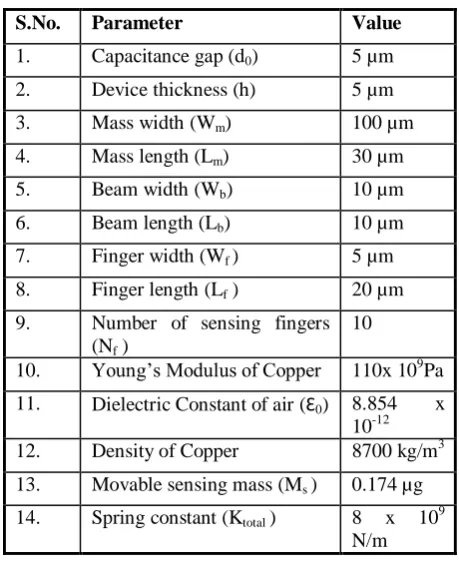
Table I Geometrical parameters of proposed accelerometer.
III. RESULTSANDDISCUSSIONS
When the acceleration is applied on the proof mass, deformation will occur and capacitance is changed as the distance between plates is changed. We consider the widths of the fingers are parameterized from 1 to 9 µm to increase the sensitivity. When the width of the plates is increased while the distance between plates is decreased, then capacitance is increased. From the simulation analyses, it has been observed that the beam width found to be vital parameter that resulting changes in sensitivity. The numbers of vertex, edge and boundary elements are 124, 422, 1300 respectively.
S.No. Parameter Value
1. Capacitance gap (d0) 5 µm
2. Device thickness (h) 5 µm
3. Mass width (Wm) 100 µm
4. Mass length (Lm) 30 µm
5. Beam width (Wb) 10 µm
6. Beam length (Lb) 10 µm
7. Finger width (Wf ) 5 µm
8. Finger length (Lf ) 20 µm
9. Number of sensing fingers (Nf )
10
10. Young’s Modulus of Copper 110x 109Pa
11. Dielectric Constant of air (Ɛ0) 8.854 x 10⁻¹²
12. Density of Copper 8700 kg/m3
13. Movable sensing mass (Ms ) 0.174 µg
14. Spring constant (Ktotal ) 8 x 10⁹
N/m
(a)
[image:2.595.326.556.267.553.2]International Journal of Innovative Technology and Exploring Engineering (IJITEE) ISSN: 2278-3075, Volume-8 Issue-8, June 2019
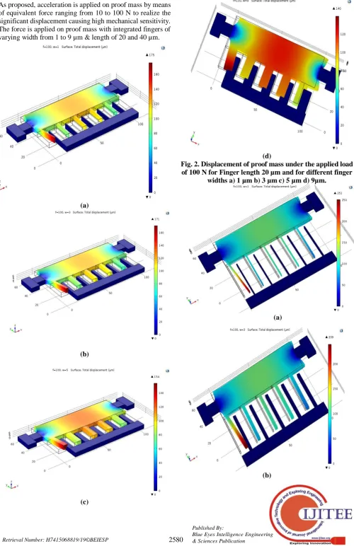
As proposed, acceleration is applied on proof mass by means of equivalent force ranging from 10 to 100 N to realize the significant displacement causing high mechanical sensitivity. The force is applied on proof mass with integrated fingers of varying width from 1 to 9 µm & length of 20 and 40 µm.
(a)
(b)
(c)
[image:3.595.49.550.61.834.2](d)
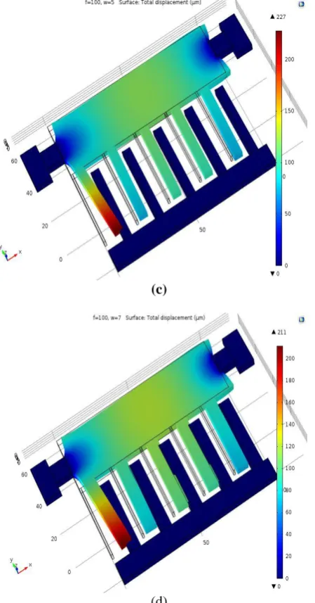
Fig. 2. Displacement of proof mass under the applied load of 100 N for Finger length 20 µm and for different finger
widths a) 1 µm b) 3 µm c) 5 µm d) 9µm.
(a)
(c)
(d)
Fig. 3.Displacement of proof mass under the applied load of 100 N for Finger length 40 µm, different finger widths
a) 1 µm b) 3 µm c) 5 µm d) 9µm.
[image:4.595.310.564.46.575.2]With increase in the width of the fingers for the constant load of 100 N, the displacement of proof mass is found to decrease. It could be due to the fact that increase in finger width causes decrease in distance between plates. Further, it is also evidenced that increase in finger width from 1 to 9 µm and load 100N causes variation of displacement of proof mass from 175 to 140 µm with finger length 20µm and 251 to 191 µm with finger length 40 µm. There was a linear change in displacement with respect to various loads ranging from 10 to 100 N that could be seen from the Table III & IV. Table II & III. Displacement of proof mass in response of applied force, Length of fingers and width of Fingers.
Table II
Table III
Length of the fingers 20 µm Fin
ger Wi dth Wf
(µ m)
9 7 5 3 1
Fo rce (N)
Displacement (µm)
10 14 14.9 15.4 17.1 17.5
20 27.9 29.9 30.8 34.1 35.1
30 41.9 44.8 46.1 51.2 52.6
40 55.8 59.8 61.5 68.3 70.2
50 69.8 74.7 76.9 85.4 87.7
60 83.8 89.7 92.3 102 105
70 97.7 105 108 120 123
80 112 120 123 137 140
90 126 134 138 154 158
10 0
140 149 154 171 175
Length of the fingers 40 µm Finger
Width Wf
(µm)
9 7 5 3 1
Force (N)
Displacement (µm)
10 19.1 21.1 22.7 23.9 25.1
20 38.3 42.1 45.5 47.8 50.1
30 57.4 63.2 68.2 71.8 75.2
40 76.5 84.3 91 95.7 100
50 95.7 105 114 120 125
60 115 126 136 144 150
70 134 147 159 167 176
80 153 169 182 191 201
90 172 190 205 215 226
[image:4.595.55.280.52.481.2]International Journal of Innovative Technology and Exploring Engineering (IJITEE) ISSN: 2278-3075, Volume-8 Issue-8, June 2019
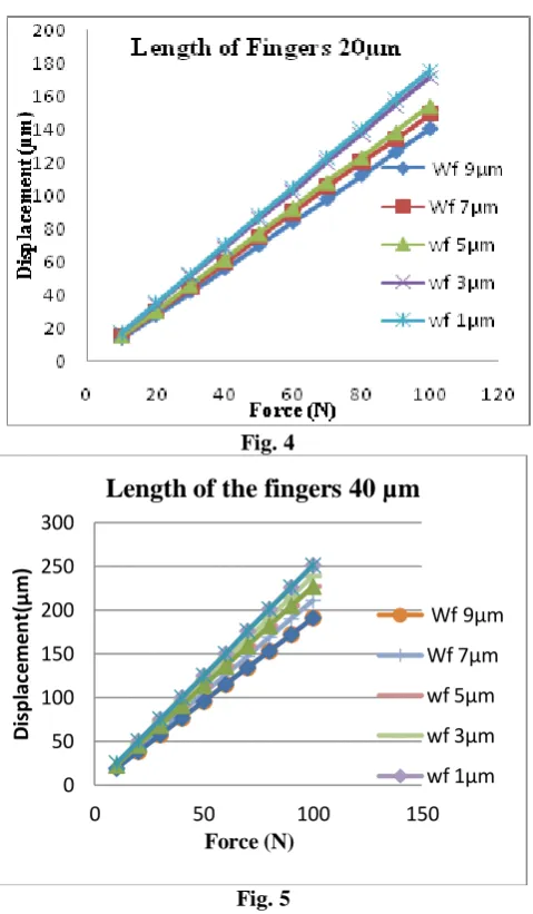
Fig. 4
Fig. 5
Fig. 4 & 5 .Variation of displacement of proof mass with applied load for different finger widths of comb drive
capacitive accelerometer.
The displacement sensitivity [12] is calculated for the different finger widths (9, 7, 5, 3, 1µm). When the width of the fingers decreased, then the sensitivity is found to increase. The corresponding values are presented in Table IV.
[image:5.595.309.539.47.220.2]Table IV Displacement Sensitivity variation with finger width
Fig. 6. Displacement Sensitivity variation with finger width.
The sensitivity is the ratio of displacement to applied force. From the results, it is clear that the sensitivity is increased with respect to the increase in width of the fingers, length of fingers. The length of fingers is changed from 20 µm to 40 µm so that sensitivity is increased.
(a)
(b)
Fig. 7(a) & (b): Capacitance at Force 100N and width 1µm and 9µm respectively
0 50 100 150 200 250 300
0 50 100 150
D
is
p
la
ce
me
n
t(
µ
m)
Force (N)
Length of the fingers 40 µm
Wf 9µm
Wf 7µm
wf 5µm
wf 3µm
wf 1µm
0 0.5 1 1.5 2 2.5 3
0 5 10
S
e
n
si
ti
v
ity(µ
m
/N
)
Width of finger(µm)
Lf=20 µm
Lf=40 µm
Lf(µm) Wf (µm) 9 7 5 3 1
20
Sensitivity (µm/N)
1.42 1.49 1.54 1.71 1 . 7 5
40
[image:5.595.315.554.325.697.2]Table V. Capacitance Values with finger width from 1 to 9 µm.
Width (µm) Capacitance (nF)
1 -4.62e-18
3 3.80e-20
5 3.78e-18
7 7.30e-20
9 6.19e-19
IVCONCLUSION
A comb type capacitive MEMS accelerometer has been designed and simulated under conditions of varying integrated finger width (1 to 9 m) for the applied force of 10 to 100 N. With increase in the width of the fingers for the constant load of 100 N, the displacement of proof mass is found to decrease. It could be due to the fact that increase in finger width causes decrease in distance between plates. Further, it is also evidenced that increase in finger width from 1 to 9 µm causes variation of displacement of proof mass from 175 to 140 µm for the load of 100 N. From the simulation results, it is clear that with increase in the length of the finger, the displacement of proof mass also increased while keeping load and widths of fingers constant. Thus it can be allowed us to conclude that there is an absolute linear relationship between applied load and displacement of proof mass including length of the fingers. These results would be useful for the development of a low noise and highly sensitive MEMS Capacitive accelerometers with wide range of capacitance.
ACKNOWLEDGMENTS
The authors would like to thank NPMASS, Govt. of India for establishing NMDC in our institution that facilitates to carry out this work and Management, LBRCE for their continuous motivational support.
REFERENCES
1. M. Benmessaoud, Mekkakia, Maaza Nareddine, “Optimization of MEMS Capacitive Accelerometer”, Microsystems Technology 19 (2013), pp.713–720.
2. Z. Mohammeda, G.Dushaq, A.Chatterjeeb, M. Rasras, “An optimization technique for performance improvement of gap-changeable MEMS accelerometers” Mechatronics (Elsevier), 54 (2018) 203-216.
3. Z. Mohammeda, M.Rasras, “Optimization of Finger Spacing and Spring Constant in Comb type Capacitive Accelerometer”, (2017) 1-2. 4. Z. Mohammed, G. Dushaq, A. Chatterjee and M. Rasras, “Bi-axial Highly Sensitive ±5 g Polysilicon based Differential Capacitive Accelerometer”, Microelectronics and Microsystems, Montpellier, France, IEEE, 2016.
5. Albarbar and S.H. Teay, “MEMS Accelerometers: Testing and Practical Approach for Smart Sensing and Machinery Diagnostics”
Springer International Publishing Switzerland, Advanced Mechatronics and MEMS Devices II, Microsystems and Nanosystems
(2017) 19-40.
6. A. Joshi, S. Redkar, T. Sugar, “Characterization of Capacitive Comb-finger MEMS Accelerometers”, Bulletin of Electrical Engineering and Informatics, 4 (2015) 320-333.
7. K. N. Khamil, K. S. Leong, N. Bin Mohamad, N. Soin, Norshahida Saba ,”Analysis of MEMS Accelerometer for Optimized Sensitivity”,International Journal of Engineering and Technology,6(2015),2705-2711.
8. F. Edalatfar, B. Yaghootkar, A. Qader A. Qureshi, S.Azimi,A. Leung, B.Bahreyni, “Development of a micromachined accelerometer for particle acceleration detection” Sensors and Actuators A(Elsevier), 280(2018), 359-367.
9. Jacek Nazdrowicz, Michal Szermer, Cezary Maj and Andrzej Napieralski, “Different Methods of Capacitive Comb Drive MEMS Accelerometer Simulations” IEEE,(2018), 254-256.
10. B. Homeijer, T. Dev., D. Lazaroff, D. Milligan, R. Alley, J. Wu, , “Hewlett Packard’s seismic grade MEMS accelerometer”, IEEE. 11. Dan Zhang and Bin Wei,” Modelling and Analysis of a Type of
Capacitance Based Accelerometer” International Journal of Mechanical Engineering and Robotics Research, 6(6).2017,434-438. 12. Sharma K, Macwan IG, Zhang L, Hmurcik L, Xiong X “Design
optimization of MEMS comb accelerometer”. Department of electrical and computer engineering, University of Bridgeport, Bridgeport, CT 06604.
13. Lee,Innam,Yoon,Gil,Park,jungyul,Seok,Seonho,Chun
Kukjin,Lee,Kyo”Development of the vertical capacitive accelerometer”Elsevier,119(1),2005,8-18.
AUTHORSPROFILE
Anusha Ganta Pursuing Ph.D.with Specilization of Micro-Electro-Mechanical Systems (MEMS) in Annamalai University,Chidambaram. She has completed M.Tech (Embedded Systems) from JNTUH, and B.Tech (Electronics and Instrumentation Engineering) from JNTUK. She is having 5 years of Teaching Experience and Published 3 papers in International Journals of repute.
Dr. T. Satyanarayana working as a Professor in the Dept. of Electronics and Instrumentation Engineering, Lakireddy Bali Reddy College of Engineering (A) since 2010. He has completed Two Sponsored Research Projects, published 45 papers in highly repute International Journals and presented more than 40 papers in International /National Conferences that includes at USA, Japan, Spain, Portugal & Poland. He is recipient of FCT Fellowship, Portugal and Best Researcher Award from JNTUK Kakinada.