International Journal of Innovative Technology and Exploring Engineering (IJITEE) ISSN: 2278-3075,Volume-8 Issue-12, October, 2019
Abstract: Damaged or broken parts are generally too expensive to replace, or no longer available. Re can be defined as ‘systematic evaluation of a product with the purpose of replication. This includes design of a new part, copy of an existing part, recovery of a damaged or broken part, development of model accuracy and inspection of a numerical model. Task is to reproducing the geometries of aero engine physical component in digitizing process through 3D scanning and complete conversion of physical data into CAD model by using modern measuring machines with its integrated software’s (creo 2.0) extractions of information about geometry to develop part models parts which have to be reverse engineered. CMM inspection and reverse engineering software are employed to evaluate any dimension deformations. Deviation in the dimension is taken in to consideration as evaluating characteristics. The error analysis of some features between 3D scan data, CMM, CAD model, and MESH data are performed.Deviation between scan data, CAD model, and CMM are within acceptable limits. And deformation between CAD model and MESH data are within -0.1 to +0.1mm. The CAD model generated is within acceptable criteria (30 microns).
Keywords : geomerties, reverse engineering, scanning, cad. I. INTRODUCTION
Reverse engineering is swiftly rising discipline, it covers huge number of actions. In this manuscript we are only concerned with reverse engineering of shape, but a broader explanation of design intents and mechanisms are achievable.Traditional engineering transforms engineering ideas and models into real parts, in reverse engineering real parts are transformed into engineering models and thoughts. The advantages and broad use of CAD/CAM systems need not be reiterated here. The reality of a computer model provides huge improvement in the quality and effectiveness of design, manufacture and analysis. Reverse engineering usually starts with measuring already present item so surface or solid replica can finish off in order to utilize the advantages of CAD/CAM technologies. There are relatively a bunch of application areas of reverse engineering. It is frequently necessary to create replica of a part, where no distinctive drawings or credentials are accessible. In other cases we may want to re-engineer an offered part, when analysis are necessary to create a new enhanced product. In areas where visual design is mostly important such as in the automobile industry, real-scale wood
Revised Manuscript Received on October 10, 2019 * Correspondence Author
G.Bharath Raj*, P.G.Scholar, Dept. of Mechanical Engg., Vidya Jyothi
Institute of Technology, Hyderabad, India. Email:
Dr.G.Sreeram Reddy, Dept. of Mechanical Engg., Vidya Jyothi
Institute
of Technology, Hyderabad, India. Email: [email protected]
Dr. L.Madan Ananda Kumar, , Dept. of Mechanical Engg., Vidya
Jyothi Institute of Technology, Hyderabad, India. Email: [email protected]
or clay models are required because stylists often rely more on evaluating real 3D objects than on presentation projections of objects on high resolution 2D screens at compact scale. Another important part of application is to generate custom fits to creature surfaces, for assembling components such as helmets, space suits or prostheses. Lee et.al. (1998) [1] projected a novel method that integrates technique of Reverse Engineering(RE)and Rapid Prototyping (RP) technology. Feng et al. (2001) [3] offered the outcome of scan deepness and estimated angle on the digitizing precision of a laser/CMM scanning system. Speckle noise in the CCD laser images was takes as the primary source of random error. A bilinear practical model had been established and was able to present predictions of the logical error with less than 25 µm variations. Son et al. (2002)[4] initiates an automatic laser scanning system which can automatically create a scan plan by investing a difficult free-form part whose CAD model was known (Lee and Woo, 1998). The automated part positioning method could save much time, improved the eminence of captured data and registration method was simplified. Thereby, unnecessary data processing was drastically reduced and errors caused by human operator might be minimized. Bardell et al. (2003) [5] had projected process of automating the confirmation of an acceptable free-form surface, by means of Coordinate Measuring Machine (CMM). Computer-aided geometric design (CAGD) was used to calculate the surface for optimum continuity and assessed CMM data accurateness. Park and Chung (2003)[6] had anticipated a course of action through which 3-axis NC tool paths (for roughing and finishing) might be directly generated from calculated data (a set of point sequence curves). An algorithm is employed to concluding tool-path based on well-known 2D geometry algorithms had been developed to keep away from difficult time-intense computational. Xie et al. (2005) [7] had proposed a multi-probe measuring system incorporated with a CMM, structured-light sensor, trigger probe and rotary table. Two types of scanning approach which was multitier scanning method and rotating scanning method had been used (Chung and Liao, 2001). Lin et al. (2005) [8] had developed the measure technique to get the better data points and the appropriate technique to deal with points cloud data. Reverse engineering software was then used to construct the free-form objects by using point data. Mohammad Shadab et. al. (2006) [9] created the use of reverse engineering system on modeling of Pillion step holder of Hero CBZ Motor Bike. The CAD replica of Pillion step holder had been performed by CATIA V5 using the cloud data. The stress study of pillion step holder was also done.
Reverse Engineering on Jet Engine Turbine Disk
Outcome revealed that the highest stress at critical section was within the acceptable limit as compared to the strong point of the objects and the deflections in the part were much lesser than the acceptable value. Again the stress analysis was performed on the customized CAD model. It was found that the highest stress and highest deflection was still within the permitted limit. It helped to identify the execution of CAD model under various loading situation and further helped to transform it. F. Belarifi et. al. (2008)[10] projected a technique for optimize the module of cutting conical spur gear, after being worn or wrecked, with the aid of Computer-Aided Design (CAD). It also tolerable for creating a actual model, by theoretical statistical uniqueness, and calculate the capacity. The recommended method is determining the geometric features of a pair of conical spur gear after damaged. A simulation package, R2000, used and unique “AutoCAD” software had been developed to complete the drawing of 2D wheel conical spur gear, the confirmation of the system assembly and the drawing of a 3D volume pattern. M. Manzoor Hussain et. al. (2008)[11] explained about development of computer technology resulted in combination of design and manufacturing systems and automated scrutiny/gauging systems in production engineering applications. Geometrical information of part was obtained openly through a physical shape through a digitizing gadget, from this total 5-axis tool path was obtained.
Photo copy of part was prepared by using CMM and CAD/CAM software like Master cam, ProEngineer etc. CMM is employed for digitizing mechanical entity. Taking coordinates of different points over the surface of the object and changing it into IGES file and using the identical in the CAD/CAM software with essential interfacing created a surface or solid model of the object. Finally solid model was used to produce CNC part program to manufacture the part on CNC Machining center. A.R. Ismail et. al. (2009) [12] described the designing and machining of four stroke engine by Reverse engineering technique. The procedure included digitizing method with the help of layout machine to arrest the point clouds and following by the Computer Aided Design (CAD) stage and Computer Aided Manufacturing (CAM) stage using Unigraphics NX2 software to recreate the piston engine surface. Then, machining process with Computer Numerical Control (CNC) machine was used to produce the piston head engine. Finally, the precision of the replicated piston engine was examined by using Coordinate Measurement Machine (CMM) and block gauge. Bhupender Singh et. al. (2011)[13] defined the solid modeling and finite element study of crane boom via PRO/E WILDFIRE 2.0 and ALTAIR HYPER MESH with optistruct 8.0 solver Software to get the deviation of stress and displacement among variety of parts of the crane boom and feasible actions were taken to keep away from the high stress level and displacement. The solid model was produced using pro/E Wildfire 2.0 using given dimensions. Then the solid model was transferred to ALTAIR HYPER MESH and analysis of the model was approved out in OPTISTRUCT SOLVER 8.0 over given constraints. The pressure standards calculated for three load
be said that under the given situation of boom material and load carrying capacity, crane boom was in safe hands to lift the load up to 12 Ton.
II. EXPERIMENTATION A. Methodology
In this relative study turbine disk of a jet engine is made using reverse engineering procedure. The scanning is done by the scanners having white light phenomenon and dual camera technology. With white light phenomenon, the point cloud data is acquired through focusing the white light on the aero engine component and dual camera technology conversion of scan data in to CAD model following CMM inspection and inspecting the CAD model by using reverse engineering software‟s this both approached methods results are used for cross check 3D CAD model.
Fig.1 B. Experimental work
In this reverse engineering data is collected using non contact scanners which are having white light source for digitize physical components as virtual MESH data with precision of 13 µm.
Physical part model
Data acquisition
Evix scan(white light phenomenon) 0)
3D modeling by creo2.0
CMM and RE inspection
Comparing deviation between CAD,CMM,SCAN
International Journal of Innovative Technology and Exploring Engineering (IJITEE) ISSN: 2278-3075,Volume-8 Issue-12, October, 2019
This scanner is having a white light which is focused on the part which is placed on the revolving table the shape of the entity appears as a millions of points called as point cloud. On the computer screen as the laser moves around recording the entire surface shape of the object after massive point cloud data files are formed they are registered and combined in to one 3dimensional representation of the object.
Table 1.Evix 3d Pro Scanner Specifications Technical
specification
Evix scan 3Dpro
Light source type White
Number and type of cameras
2×5mpix
Scanning time 4secs
Measuring range 39.01
Ambient temp +10ºc to +30ºc
Storage temp From-20ºc to 40ºc
Later on with the help of Geomagic Wrap application, post processing for scan data was completed by patching and refining mesh and cloud data. Then mesh data is converted into solid and surface models by using Geomagic Design X application for creating curves and basic geometrical feature. Geomagic Design X tool extract the data with 4 – 10 µm deviation from scan data. Preprocessed and aligned surface models of scan data are converted into solid featured CAD models by CREO 2.0 version software. Complete extraction of geometrical features from IGES files (scan surface models) to regeneration of virtual model with categorized feature tree. After completion of CAD modeling of components, CMM inspection is employed to evaluate any deviations between 3D scan data and CAD models. The job was done on Nikon Altera + CMM platform with accuracy of 1.5 µm with 1 mm probe head. Some crucial geometrical values are taken to cross check with CAD dimensions. And reverse engineering
software is used to inspect Deviations in shape orientation and dimensions.
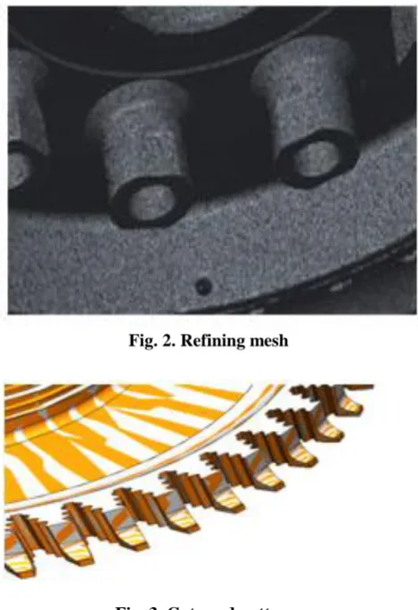
[image:3.595.309.544.73.416.2]Fig. 2. Refining mesh
Fig. 3. Cuts and patterns III. RESULTSANDDISCUSSION
[image:3.595.41.566.565.723.2]Deviations in the proportions are taken into account as evaluating characteristics. The error analysis between 3D scan data, CMM and CAD models and mesh data are shown in below tables.
Table 2.Deviations from 3D Scan Model Part
Feature
3D Scan Model CMM CAD Model Scan – CAD Deviation CMM - CAD Deviation
Hub diameter 49.937 50.020 49.937 0.000 -0.083
Boss inner dia-1 14.158 14.490 14.160 0.002 -0.33
Boss inner dia-2 14.158 14.231 14.160 0.002 -0.071
Bosses center circle dia 159.923 159.984 160.260 0.337 0.276
Rim fin-1 outer dia 267.743 268.500 267.743 0.000 -0.757
Rim fin-2 outer dia 267.750 268.000 267.750 0.000 -0.25
Boss inner dia-9 15.392 15.461 15.390 -0.002 -0.071
Boss inner dia-9 15.392 15.461 15.390 -0.002 -0.071
Root thickness 11.880 11.855 11.884 0.004 0.029
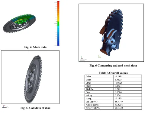
Fig. 4. Mesh data
Fig. 5. Cad data of disk
Fig. 6 Comparing cad and mesh data
Table 3.Overall values
Min -6.2891
Max 6.3135
Avg -0.0028
Rms 0.2421
Std.Dev 0.2421
Var 0.0586
+Avg 0.136
-Avg -0.1351
In Tol.(%) 56.4749
Out Tol.(%) 43.5251
Over Tol.(%) 20.3322
Table 4.Deviation analysis
No TOLERANCE GAP
DIST
REFERENCE POS MESURED POS
X Y Z X Y Z
1 ± 0.1 0.5011 77.86 47.88 -988.6 78.25 47.7 -988.8
2 ± 0.1 0.0061 99.35 140 -960 99.3 139 -959.9
[image:4.595.46.338.426.704.2]3 ± 0.1 -0.2057 51.14 120 -820 50.9 120 -820
Fig. 7 Comparing cad and mesh data
CAD data and mesh data are assembled in the reverse engineering software to find out the dimensional deformations of the created CAD model. Figure 7 shows the
colour in figure 6. The yellow region in the figure 6 represents the deformation and the gap distance between the CAD and MESH data. Maximum, minimum, standard deviation and some numerical values are shown in the table 3. And gap distance Between mesh and cad model is shown in the above Table 4.
IV. CONCLUSION
The case studied has permitted us to find out how reverse engineering can be helpful for CAD model generation and developing already existing parts. This thesis depicts how a 3D scanner works and its applications in reverse engineering and collecting the data of the entity with the help of scanner. Also different software is used to create the mesh and define the position of the mesh. CREO is employed for creating CAD model of the complex aero component by drawing the different surfaces, points and
International Journal of Innovative Technology and Exploring Engineering (IJITEE) ISSN: 2278-3075,Volume-8 Issue-12, October, 2019
Author-1 Photo
Author-2 Photo
Author-3 Photo
employed to evaluate any deviations between 3D scan data and CAD model. Deviations are taken in to consideration as evaluating characteristics. The error analysis of some features between 3D scan data, CMM, CAD model, and mesh data are performed. Deviation between scan data, CAD model, and CMM are within acceptable limits And deformation between CAD model and mesh data are within -0.1 to +0.1mm. The CAD model generated is within acceptable criteria (30 microns) and CAD model can be used for manufacturing.
REFERENCES
1. L. Li, N. Schemenauer, X. Peng, Y. Zeng, P. Gu, A reverse
engineering system for rapid manufacturing of complex objects, Robotics and Computer-Integrated Manufacturing. 18, 1, (2002) 53
2. T. Várady, R. R. Martin, J. Cox, Reverse engineering of geometric
models, Computer-Aided Design. 29, 4 (1997) 255-268.
3. Brajlih, T., Tasic, T., Drstvensek I., Valentan B., Pogacar, V.,
Balic, J., Acko, B.: Possibilities of using three-dimensional optical scanning in complex geometrical inspection. Strojniski vestnik - Journal of Mechanical Engineering, vol. 57, 11, (2011) 826-833.
4. Eck, M, DeRose, T, Duchamp, T, Hoppe, H, Lounsbety, M and
Stuetzle. W „Multiresolution analysis of arbitrary meshes‟ Computer
Graphics (SIGGRAPHPS Proceedings) 29, 1995, 173-182.
5. Technological documentation for ATOS GOM II optical scanner,
Braunschweig, Germany: GOM, 2007.
6. 3D Scanning Gallery for Industry Applications: [Internet]. 3D
Solutions.Avaliable at: http://www.3d3solutions.com/resources/ [22.5.2013]
7. Skifstad, K ‘Rising above the data clouds’ Computer Graphics
World 18(2), 1995, S4-S12.
8. Chase, K W and Greenwood, W H 'Design issues in mechanical
tolerance analysis', ASME Manf. Rev., Vol 1 No 1 (1988) pp 50-59.
9. Fu, P. (2008). In Reverse engineering: An industry perspective,
Springer, ed. V. Raja and K. J. Fernandes, 177-193. Berlin.
AUTHORS PROFILE
Golla Bharath Raj P.G.Scholar, Department of
Mechanical Engineering, Vidya Jyothi Institute of
Technology, Hyderabad, India. Email:
Dr G Sreeram Reddy, awarded with PhD degree from
JNTUH in the area of Reverse Engineering with more than 25 publications. He is member of ISTE and IWE.
Dr L Madan Ananda Kumar. Awarded with PhD