Rochester Institute of Technology
RIT Scholar Works
Theses
Thesis/Dissertation Collections
1989
Amused: a multi-user software environment
diagnostic
Mary Ann Foltman
Follow this and additional works at:
http://scholarworks.rit.edu/theses
This Thesis is brought to you for free and open access by the Thesis/Dissertation Collections at RIT Scholar Works. It has been accepted for inclusion
in Theses by an authorized administrator of RIT Scholar Works. For more information, please contact
Recommended Citation
Rochester Institute of Technology
School of Computer Science and Technology
AMUSED:
A
Multi-User
Software Environment
Diagnostic
by
Mary Ann Foltman
A thesis. submitted to
The Faculty of the School of Computer Science and Technology,
in partial fulfillment of the requirements for the degree of
Master of Science in Computer Science
Approved by:
John A. Biles
Karen K. Anderson
Peter G. Anderson
THESIS
RELEASE PERMISSION FORM
ROCHESTER INSTITUTE OF TECHNOLOGY
College of Applied Science and Technology
Title of Thesis:
AMUSED:
A fulti-User Software Environment Diagnostic
I,
Mary Ann Foltman,
hereby grant permission to the Wallace
Memorial Library of R.I.T.
to reproduce my thesis
in whole
or in part.
Any reproduction will not be for commercial
use or profit.
Abstract
As
software projects growin
size andcomplexity,
many
individuals
take
over
the
responsibilitiesfor
oneproject,
creating
a potentialfor
new errorsin
the
development
process.Software
versioninconsistency,
unfamiliarity
withthe
tools
used,
and softwaretool
restrictions arebut
some ofthe
problemsencountered
in
a multi-programmer environment.These
problems are notalways self-evident
to the
programmer andmay
require adedicated
softwaresupport representative or experiencedprogrammers
to
assist.These
problemscan
be
reducedthrough
the
development
of a multi-user softwareenvironment
diagnostic
expertsystem,
AMUSED (A Multi-User
Software
Environment Diagnostic). The AMUSED
expert systemis designed for
useby
programmers responsible
for
creating the
executable software releases on astandard copier
/
duplicator
project.Project
source codeis
transported to
acommon
workstation,
andlinked
together
with otherprogrammers' code
through
alinking
tool.
AMUSED's diagnostic
help
assists(a)
the
link
processthat
willbe
usedto
createthe
executable codefrom
the
sourcefiles,
(b)
the
retrieval of source
files from
remote sitesto the
link
workstation,
and(c)
the
use of
any
interfacing
connectionsbetween
the
source modules.Keywords
Expert
system,
software configurationmanagement,
softwareAcknowledgements
During
the
entirethesis
process,
a network ofpeople was establishedto
help
supportthis
project.Numerous
people provided resourcesand referencesduring
the
course ofdevelopment.
Among
these
people aremy
advisors,
whoinclude: Al
Biles,
Rochester Institute
ofTechnology
graduateinstructor;
Karen
Anderson,
a systems engineer atXerox
Corporation;
andDr.
Peter
Anderson,
Graduate
Computer
Science
Department Head
atRIT.
For
the
development
phase ofthe
project,
several people who werefamiliar
with
the tools
used were availablefor
consultation.Dennis
Brantly
assistedwith
the
use ofInterlisp,
andKathy
Matysek
assisted with problems withCommon Lisp. People
on various software projects atXerox
andRank Xerox
were also contacted.
These
contacts provoded usefulinformation
onhow
errors are
handled in
eachgroup,
as well as on which errorsaremost commonand critical.
They
also supplied much ofthe
data
which was enteredinto
AMUSED.
The
contactsincluded: Mike
Sprague,
Mary
Beth
Anderson,
Karen
Maloney,
Bob
Harwood,
andMarlene
Yaw
ofXerox
Corporation
in
the
USA,
andDennis Miazga
andDave
Bradley
ofRank Xerox
atWelwyn Garden
City,
England.
Other
people withinXerox
have been
ableto
provide otherinformation
as well.This
information
was oftenin
the
form
of referencearticles,
new peopleto
contact,
or otherareasto
research.Among
these
peopleare
Bill
Anderson,
Jack
Bacon,
andCynthia Nyborg.
Other
peoplethat
I
wishto
acknowledgeinclude
my
managers atXerox,
AMUSED
Table
ofContents
1. Introduction
1
1.1
The Multi-User
Software
Environment
1
1.2
The General Software Development Process
2
1.3
An Expert
System Application
3
1.4
Chapter
Summaries
4
2. Background
5
2.1
Review
ofPast Projects
5
2.1.1
Software development
projects5
2.1.2
Related Expert
Systems
6
2.1.3
Related
Xerox
Projects
20
2.2
Languages
andTools
26
2.2.1
Common
Lisp
26
2.2.2
TMYCIN/EMYCIN
28
2.2.2.1 EMYCIN
28
2.2.2.2
TMYCIN
30
2.2.3
Discarded
Tools
31
2.3
Present System
atXerox
35
3. Implementation
38
3.1
System Overview
38
3.2
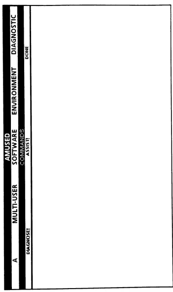
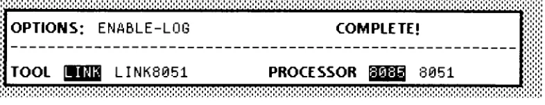
AMUSED Appearances
39
3.3 User
Tutorial
42
3.3.1
Diagnose
Walkthrough
42
3.3.2
Assist
Walkthrough
47
3.4 Technical
Overview
50
3.4.1
Basic Control
Flow
50
3.4.2
Diagnose
Options
51
3.4.3 Initial
Questions
52
3.4.4
Asking
Questions
53
3.4.5
Processing
Questions
55
3.4.6
Certainty
Factors
56
3.4.7 Distributed
Rule Bases
56
3.4.8 Question
Database
58
3.4.9
AssistMode
60
3.5
Summary
60
4
Testing
64
4.1
Data Collection
64
4.2
Early
Implementation
Results
65
4.3
Testing
66
5.
Conclusion
67
5.1 AMUSED
Shortcomings
67
5.2 Alternate
Approaches
68
5.3
Possible Extensions
69
AMUSED
References
71
Appendix A
--DFFile Sample
74
Appendix B
-TMYCIN
Data Flow Diagrams
76
Appendix
C
~TMYCIN Function Description
81
Appendix
D
-AMUSED Flow Charts
82
1.
Introduction
1.1
The Multi-User Software Environment
Over
the years,
software projectshave
grownin
size and complexity.Many
projects
have
expandedto
such magnitudesthat
they
cannotbe
written andmaintained
by
one or even afew
programmers.When
morethan
oneprogrammer
takes
overthe
responsibility
for
a given software module orsubsystem,
alayer
ofcomplexity
is
addedto the
original project.This
complexity
is
compoundedby
the
challenges ofmaintaining
softwareconsistency.
Programs
that
consist ofalarge
number of modules needto
be
managed.When
the
number of modulesmaking
up
a system exceeds somesmall,
manageable
set,
aprogrammer cannotbe
surethat every
new version of eachmodule
in
the
program willbe handled
correctly.After
each versionis
created,
it
mustbe
compiled or assembled.The
programmerthen
may
needto
storeit
somewhere so othersmay
useit. The
versions ofthe
softwarebeing
transferred
cannotbe
guaranteedto
be
correct without someform
ofassistance
[SCHMTDT82].
During
development
and maintenance ofthese
large
software,
systems,
adifficult
problemalwayshas
been
ensuring that the
correct versions ofsourceandobject
files have
been
used.As
the
number of programmersand softwaremodules
increases,
the
cost of mistakes escalates.This
problem also expandswhen software references are
duplicated
across a network of personalworkstations.
It is
complicatedfurther if
the
softwareis developed in
astrongly
typed programming
language
such asXerox'
Mesa,
whichdemands
that
allreferencesto
a module agreeexactly
in
softwareversion.Such
versionchecking
provides another checkin
the
software process and allows errorsto
be
caughtsoonerin
the
softwaredevelopment
cycle.Such
additional workup
front, however,
also can createfrustration in
the
pushto
reachdeadlines
1.2
The
General
Software Development
Process
Software development
ofteninvolves
a common set of steps specificto
agiven environment.
Whether
the
softwareis
developed
in
ahigh level
language
orin
assembly
code,
a certain set of steps needsto
be followed
to
produce
the
desired
result.Many
ofthese
steps aredependent
uponthe
environment
being
used andthe
size ofthe
project.The
use of softwaretools
generated within
Xerox for
that
specific softwaredevelopment
environmenthelps
to
guarantee process commonality.In
the
multi-userenvironment,
programmersindividually
writetheir
ownsoftware,
but
the
amountofindividual
testing
that
canbe done is limited.
The
software modulesare nextassembledor compiled.
Modules
arethen
storedin
a commonfacility
such as afile
server or workstationfor later
retrieval.As
in
some
high level
languages,
two
separatesections of a module existto
registerthe
interdependencies
ofthe
modules.The
interface
modulesdefine
the
data
abstractions and
the
implementation
modulesimplement
and usethe
data
listed in
the
interfaces.
When
this
format is
used,
the necessary
completedinterface
modules are retrieved as needed.The
first
two
steps ofthe
process,
that
ofcompilation/assembly
and storage ofmodules,
arethen
performed onthe
implementation
modules.Once
all code changeshave
been
completed,
all modulesare retrieved ontoa
designated
workstation,
wherethey
are combinedthrough
another softwaretool,
suchasthe
Xerox
tools
Link
andLink8051,
into
an executable version ofthe
software.Link
andLink8051
areabsolutemapping tools that take
source codefrom
varying
languages
andmap
them
directly
to
aresulting
executablefile
withthe
correct addresses neededby
the
specifiedIntel
processor.This
executable
file
couldbe
amemory
image file
(MIF
file)
whichis
specifically
used asinput
to the
softwaretools
for interactive testing,
anIntel
objectformat
file,
or ahex file. The hex
files,
mostcommonly
usedin many
Xerox
input
usedto
createthe
EPROMs
to
runthe
products,
but it
also canbe
usedasan
interactive
test
file.
Several
common activities arisefrom
the
linking
process.The
mostcommon
activity is
integrating
the
assorted software modulesinto
anexecutable
file
using
the
Link
andLink8051
tools.
These
two tools
are neededto
combine a widevariety
oflanguages
into
a common executable element.The file
manipulation scheme andthe
linking
tools
arethe
main areas ofinterest
addressedby
this
project.One
ofthese
areasofinterest is
the
manipulation offiles
among locations.
Three
maintools
arecommonly
usedfor
the
storage and retrieval offiles. The
File Transfer
Program
(FTP)
is
a command set runfrom
the
executive windowin
the
Xerox
Development Environment
(XDE).
It
is
mostcommonly
usedin
association with a
file
that
lists
the
commandsto
be
executed withthe
necessary
switches.FileTool is
anindependent
tool
that
provides abetter
interface
to the user,
but it
performsthe
samebasic
functions
asFTP.
The
Describe File
Tool
(DFTool)
uses adescription
file,
known
as aDF
file,
to
allowfiles
to
be
stored and retrieved whilemonitoring the
versionsbeing
used.This
tool
willbe discussed
in
depth later
in
the
paper.1.3
An
Expert System
Application
A
variety
of software problems can occur on a copier/duplicatorproject,
especially
whenthe
projectincorporates
multiplemodules,
versions,
andstorage
locations.
With
the
properprecautions,
many
integration
problems andother errors canbe
caughtandfixed before
the
code reachesthe
hardware
to
be
tested.
AMUSED is
an expert systemtool
that
will provideprogrammers
in
a multi-user environment withdiagnostic
assistancein
the
linking
orabsolutemapping
phase of a software project.AMUSED
makesit
easier
to
pinpoint problems withthe
basic
linking
package,
as well asproblems with
file
versions,
and variable misuse.By
circumventing
the
software preparationstage,
AMUSED
increases its
potentialusability,
sincemany
software projects atXerox
use one ofthe two
mainlinking
tools
with a1.4
Chapter
Summaries
This
paperdescribes
the
AMUSED
systemin depth
and provides aninformational background for
relatedtopics.
Chapter
One has
been
anintroduction
to the
processrequiring
the tool.
Chapter
Two
will providebackground
on other research and projectsin
the
same and relatedfields,
aswell as
in-depth information into
the tools
usedfor
the
project.Chapter
Three
explains
the
actualimplementation
ofthe
project.Chapter Four
examinesthe
results of
the
implementation
including
usersampling
and responsetimes.
Chapter Five
containsthe
conclusions obtainedfrom
the
research.Appendix
A
contains a sample ofDF
file. The
TMYCIN
data flow
diagrams
arein
Appendix
B,
whileAppendix
C
contains afurther
description
ofthe
funcitons
within
TMYCIN.
Appendix D
containsthe
flowcharts
describing
the
layout
ofAMUSED,
andthe
final
appendix contains acopy
ofthe
source codefor
2.
Background
2.1 Review
ofPast Projects
While
muchdevelopment
has happened
in
recent yearsin
the
area of version control withinXerox,
noneofthe
applicationshas incorporated
expert systems or artificialintelligence.
In
contrast,
a small number of systems outsideXerox have been developed
that apply
somedegree
of artificialintelligence
to the
softwaredevelopment
process,
but
none execute proper version control.Although
only
a small number of related references werefound,
those
resourcesdid
offer goodinsight
to
pastworks,
including
those
with artificialintelligence
applicationsandthose
without.2.1.1
Software
development
projectsAlthough
expertsystems andthe
use of artificialintelligence
arethe
majorconcerns with
the
AMUSED
project,
someinteresting
insights
werefound
from
a projectin
which a software maintenance scheme wasdeveloped
for
alarge
European
computer manufacturer.Similarities
werefound between
large
software projects andmachinery
withassemblies,
sub-assemblies andparts
[MARC84].
This
connection alsobrought
up the thought that
gooddesign
naturally
leads
to
maintainablesoftware,
but
maintainable softwarerequires more
than
a good softwaredesign.
Controlling
softwaremanufacturing
requires a centralizeddatabase
to
collectinformation
onthe
software such asstatus, quality,
and structure.This database
concept workslike
an expert systemto
handle
the
systemcomplexities.
Differences
canbe
notedbetween
well-developedsoftware,
whichneedsaone-time controlledconfigurationprocess,
andwell-maintainedsoftware,
which canbe
regenerated atany time
[MARC84].
Information
onconfiguring
a particularversion ofa product also mustbe
preservedto
allowthat
configurationto
be
reproducedreliably
in
the
future.
One
methodfor
controlling the
reconstruction ofsoftwareconfigurationsis
to
enforce change control.Use
of change control regulates updatesto
a setof softwareby
forcing
the
changesto
be
registered and reviewedby
a selectensure
that
compilations andtests
ofcomponents aredone
identically
for
eachiteration.
Correct
versionsof alltools
usedmustalsobe
tracked
to
ensurethe
properconfiguration.2.1.2
Related Expert Systems
While
advanceshave been
madein
expert systemdevelopment
andexpecially in
integrated
environments,
Franco
Manucci
[MANU84]
mentionsthat only two
basic
streams of researchhave
evolvedtoward
improving
the
realm ofintegrated
environments,
the evolutionary
andrevolutionary
approaches.The
evolutionary
approachis
conservative,
aimedatincremental
improvements,
whilethe
revolutionary
approachis
gearedtoward replacing
the
system with an automation-based paradigmusing
artificialintelligence
techniques.
Manucci
goes onto
statethat these two
approaches willdevelop
in
parallelfor
atime,
andthat there may
be
some applications of artificialintelligence
that
willtackle
specific sections ofthe
problem.However,
he
doesn't
feel
that
artificialintelligence
couldbe
usedfor
an entirecomprehensive system at
the
presenttime
[MANU84].
In
contrast,
Boyd
[BOYD84]
feels
that
softwaretechnology
is
a goodcandidate
for
the
application ofknowledge-based
expert systems.Says
Boyd,
"Expert
systems aredistinguished
from
other conventional computersystemsby
their
explicit use of a storedknowledge base
manipulatedby
aclearly
identifiable
controlstrategy
(the
inference
engine)"
[BOYD84]. Such
systemsare capable of
achieving
alevel
of performance comparableto
ahuman
expertin
aspecializeddomain.
Boyd
statesthat this
domain
couldbe
in
one ofthree
general areas:the
applicationdomain,
the
executionenvironment,
orthe
programming
methodology.AMUSED
falls into
the
programming
methodology
category,
sinceit deals
withthe
softwaredevelopment
process.Interactive Program Design Expert System
In
discussing
interactive
programdesign,
Harandi
[HARA83]
presents anew
implementation
methodusing
knowledge-based
techniques.
Software
design
is
oftendelegated to
experienced software engineers whorely
on pastknowledge
of similar productsto
design
newsystems/
programs.However,
by
be
constructedfrom
a user specification.This
system uses aknowledge
base
with
dataflow
model segmentsto
represent programdesign
components.These
segments are combined andrefined,
using
transformation rules,
to
produce a
dataflow
model ofthe
goal program.A dataflow
contextdiagram,
while naturalfor humans
to
use,
is
alsocapableof
representing
a program modelaccurately
andin
an understandableformat.
The
types
ofdata
that
flow
through
a program andthe
transformations that
processthose
dataflows
arethe terms that
specify
the
program.
The
interior
structure ofany
transformation may
be detailed
further
by describing
adata flow diagram
(DFD),
which specifieshow
the
function
ofthe transformation
is
accomplishedin
terms
oflower
level
functions [HARA83].
When
these
data flow
diagrams,
together
with adictionary
ofdata
definitions,
arecollected,
they
canbe
usedto adequately
specify many types
of programs.The
design
aid systemimplements
a set of specificationsinto
a set ofschemas which
the
userthen
can analyzefor design intent.
Several
majorunits compose
the
system:the
knowledge
base,
consisting
ofschematicsystemdesign
information;
adata
dictionary;
andknowledge
about variousdomains
of application.
The design
refinement unitis
the
inference
engine ofthe
system,
controlling the
design
process.Responsible for
allthe
user-systeminteractions
is
the
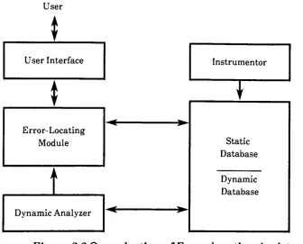
userinterface. The
organization ofthe tool
canbe
seenin
Figure 2.1. Interactions
withthe tool
occurthrough
a restricted naturallanguage
interface,
whichis implemented
through
an augmentedtransition
network
(ATN)
[HARA83]. A
graphicsinterface
alsois
providedto
facilitate
viewing
andediting
ofthe
data flow
design.
Both
major components ofthe
knowledge
base,
the
catalog
of schematicdesign
components andthe
data
dictionary,
are arrangedin
an abstractionhierarchy
to
permitinheritance
andsharing
of common components.The
meanings of
the
various components aredomain
oriented and arerepresented atdifferent levels
ofabstraction.The
design
aidtool
functions
by
receiving
specifications,
scheduling
goalsKnowledge
Base
Design
Segments
Data
Dictionary
User Interface
Graphics
Natural
Language
[image:14.547.83.480.96.298.2]Design
Refinement
Unit
Figure 2.1.
The
Building
Blocks
ofthe
Design
Aid
System
more
detailed
systemdesigns. A list
ofgoalsis
maintained and executedto
managethe complexity
ofits
variousdesign decisions. The
useris
permittedto
inspect
andmodify the
design
throughout the
design
process.Each
modification
is
checkedfor
consistency
withinthe
design
model.A final
dataflow design
canbe
usedin
a number ofdifferent
ways.It
canbe
transformed
into
a structureddesign
using techniques
such astransform
and
transaction
analysis,
simulated as adataflow implementation
orprototype,
or usedasinput
into
a programediting tool.
Users
can usethe tool
asa reference
to
seeparticulartypes
ofdataflow
models.It
also canbe
used asa
dataflow
managementtool.
The knowledge base is
composed ofa number ofdata
dictionaries,
whichare used
to
understand and validate user requirements and specifications.Data definitions
are containedin
the
data
dictionary
for
allknown data
objects
in
the
system's world model.The definitions
alsoinclude
suchinformation
as assumedvalues,
defaults,
constraints,
properties,
andpredicates.
Schemas for design
components are storedin
the
data flow
includes
transformation
definitions
and submodelsdescribing
the
input
andoutput
data
flows,
aswellas referencesinto
the
data
dictionary.
An initial
user specificationis
matched againstthe
schemasfor
any
related
diagrams
that
already
exist.This matching is done
by
names ofobjects,
key
words orphrases,
orby
exact words.If
morethan
one possibleresponse
is
found,
the
resolutionis
madeby
the
program whenever possible orelse,
a choiceis
presentedto the
user.A
list
of goalsto
be
addressedis
maintainedduring
the
development
process andis
treated
as apriority
scheduling
queue[HARA83]. Goals
canbe
addedto the
front
orthe
end ofthe
queue,
depending
onurgency.The
systemaddressesthe
nextwaiting
goal onthe
highest
priority
queue until all queues are empty.Refinements
ofgoalsalsoareaddressed on
this
queue.The dataflow design
aidtool
is
expectedto
help
reduce error proneactivities such as requirementanalysisandspecification.
This
help
shouldbe
accomplished
by
allowing
the
requirementsandspecificationsto
be
expressedata
level
as close as possibleto the
conceptuallevel
ofthe
analyst.It
wouldreduce
the
specification effortthrough the
inclusion
ofdomain knowledge
in
the
tool.
It
also would perform validation of usersspecificationsin
conjunctionwithrefinements
to
adataflow design
model.Error Localization
Expert System
Error localization
in
programdebugging
is
the
process ofidentifying
program statements
that
causeincorrect behavior.
A
prototype ofthe
errorlocalization
expert systemfor
debugging
Pascal
programs wasdeveloped
atOakland
University
[KORE86].
The
overlying
goalin
developing
this
systemwas
to
minimizethe
amount ofinformation
that the
programmer needsto
supply
to
locate
the
error.It
makes use ofthe
knowledge
of programstructurerather
than
the
knowledge
atthe
level
of symptomfault
rules.The knowledge
of program structure
is
representedby
adependence
network.The
process ofdebugging
has
generatedcomparatively
little
research,
literature
orformal instruction
comparedto
other software-developmentactivities.
Some
researcherssay
the error-locating
process represents95%
ofinclude:
the
programmer mustsimultaneously
keep
track
ofinordinate
amountsof
detail;
debugging
a programrequires ahigh
degree
of precisionto
isolate
all aspects of an error andto track
its
total
effectthroughout
the
program;
and a programmer's mind canbecome fixed
on one possible cause evenif
the
programmeris
looking
in
the
wrong
place.Generally,
the
error-locating
processis
performedby
means ofbreak-and-examine
debuggers.
Through
the
use ofbreakpoint facilities
a programmerinserts breakpoints
around suspect
instructions
wherethe
erroris believed
to
originate andthe
program
is
re-executed untilthe
offending
instruction is found.
The
Oakland
prototype[KORE86]
guidesa programmerduring
the
testing
of
Pascal
programs.As
aninteractive
system,
it
queriesthe
programmerfor
the
correctness ofthe
programbehavior
and uses answersto
focus
the
programmer's attention on an erroneous part of
the
program.The
systemmakes use of
knowledge
of program structure ratherthan
knowledge
ofsymptom-fault rules.
This
deep-reasoning
approachis different from
the
traditional
shallowknowledge
engineering
approach(i.e.
MYCIN),
whichcaptures
diagnostic
knowledge
atthe
level
of symptom-fault rules.The
traditional
approachgathersinformation
over an extended period oftime
andbecomes
very
programspecific,
which canbe
adisadvantage.
Program
structureknowledge is
representedby
adependence
network,
which
is based
onthe
concept ofdependence
relationship between
programinstructions. It is
usedby
anerror-locating reasoning
mechanismto
guidethe
construction, evaluation,
and modification ofhypotheses
of possible causes ofthe
error.Three
different
types
ofdependences
canbe
found between
programinstructions in
the
executiontrace.
First is data
influence,
whichis
represented
by
data
flow. Next is
controlinfluence,
whichis
defined between
the
test
instruction
andthe
instructions
that the test
instruction
can chooseto
execute or not execute.
The
last
type
is
a control-datainfluence,
whichhas
both
direct data
anddirect
controlinfluence
onany
instruction in
the
execution
trace
[KORE86].
Diagnostic
problemsolving
is
inherently
sequentialin
nature.It is
guidedby
ahypothesis-and-test
process,
where a programmerstarts atthe
pointthe
of events
leading
up
to the
error.Generation
of ahypothesis
based
onthese
conditions canbe
aproblem,
sinceit
might notbe
the
correcthypothesis
orthe
correct position wherethe
break
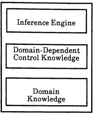
occurred.Korel's
system,
developed
to
be
anerror-locating
assistanthas five
majorcomponents,
as shownin Fig.
2.2
[KORE86].
A
static analysis ofthe
sourceUser
*
User Interface
Instrumentor
|
1
T
Static
Database
Error-Locating
Module
;
^
Dynamic
Database
Dynamic Analyzer
Figure
2.2
Organization
ofError-locating
Assistant
program
text
is
performedby
the
Instrumentor
tool.
It
then
generatesa staticdatabase
andinserts
the
executionhistory,
collecting
instructions before
every monitoring
pointin
the
sourceprogram,
which creates aninstrumented
version ofthe
original program.The
database
contains staticinformation
aboutthe
program anddynamic
information
aboutthe
program's execution.A
staticdatabase is
createdautomatically
by
the
Instrumentor
and consistsofthe
following
components: symboltable,
instruction
table,
and program [image:17.547.87.423.199.470.2]The
mainfunction
ofthe
error-locating
moduleis
to
reasonaboutincorrect
behavior
ofthe
programto
guidethe
programmerduring
the
localization
process.
This
task
is
performedby
creating
the
dependence
network,
generating
the
hypotheses
ofpossible sources oferror,
based
onthe
known
findings
ofincorrectness,
andevaluating
these
hypotheses based
onquerying
the
programmer aboutthe
correct/incorrectbehavior
ofthe
program.The
mainfunction
ofthe
userinterface is
to
provide communicationbetween
the
programmer andthe
error-locating
module.Automatically detecting
the
possible correctness
in
the
executiontrace
is
the
purpose ofthe
dynamic
analyzer.The
dynamic
analyzerperformstwo types
ofanalysis,
uninitialized variable analysisand assertionanalysis.Ericsson Public
Telecom System
A Telecom
systemis
avery
large
program,
but it is
also onethat
existsin
a numberofdifferent
versions.Managing
such a systemis
adifficult task,
andthe
concepts offeredin
the
field
of artificialintelligence
were studiedto
fill
this
need.It
was clearthat many
ofthe
problems whendeveloping
andmanaging
big
software systems concernsgetting
relevantinformation
atthe
right
time
with a minimum of effort."Object-oriented AI
tools,
also calledframe
systems,
offer a methodfor
organizing this
information going
beyond
the
capabilities oftraditional
databases"
[WELI84].
In
aframe
orienteddatabase,
the
information
is
organized asproperties ofobjects
corresponding
to
units ofthe
application,
for
example,
telecom
software modules.Inheritance
of properties and ahierarchy
of objects couldbe
created,
reducing redundancy
andallowing
storageanddisplay
ofinformation
atdifferent
levels.
This
method would also allowconsistency to
be
maintained.
Forward
chaining
production rules canbe
used either alone orin
combination with an object-oriented
database
to
makeinferences
aboutthe
software system and
the
design
process[WELI84].
By
checking
the
situations ofa givendesign
rule, the
programmer canbe
warnedif
a rule were aboutto
be
violated.Constraint
propagation andbelief
revision canbe
usedto
experimentwith alternate solutions without
changing the
actual parameters.Such
anability
would allowthe
effects ofthese
systems'
studied.
Further
support also couldbe
provided werethe
proposed expertsystem
integrated
withthe
restofthe
environment.
Ericsson
Public Telecom Division has been
conducting
these
experimentsin
artificialintelligence
overthe
pastfew
years.They
decided it
wasbetter
to
acquire a
basic
technical
competencein
the
field
andto
import
anddevelop
various
kinds
of artificialintelligence
software,
ratherthan to
buy
specializedexpert system
tools
and startbuilding
expertsystemsat once[WELI84].
POZZO
System
The knowledge-based
approachto
softwaredevelopment involves
formulating
the
domain knowledge
in
adeclarative
way
andleaving
the
procedural control
to
aninference
engine[NORD86].
An
important
problemwith
this
method ofdeveloping
softwareis
that
it is difficult
to
express andrepresents
domain-dependent
controlknowledge
(i.e.
how
the
object-levelknowledge
is
organizedby
the
personusing
it).
In
studies ofhuman
expertise,
it
wasdiscovered
that
an expert worksby
reusing
solutionsto
previous problems[NORD86].
The
use ofprototypes,
actual
implementations
ofan expert's previous experiencetaken
from
typical
cases
to
express and representdomain-dependent
controlknowledge,
follows
this
example ofreusing
problemsolutions.One important
advantage ofusing
prototypes as amethod of
representing
controlis
that
they
are additive.The
system can
be
run withoutthem,
but
clarity
andefficiency
aregainedfrom
the
additional
information
presentedby
the
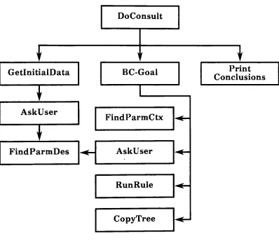
prototype cases.POZZO
wasdeveloped
using
prototypesin
conjunction with a rule-basedsystem.
The
prototypes are representedseparately
from both
the
domain
knowledge
andthe
inference
engine,
asillustrated
in
Figure 2.3. Prototypes
found
in POZZO
contained severalitems:
the
parameterconstraints, the
range ofparameter
values,
defaults
and expressionsfor
constraints;
alist
ofvalues
to
be filled for
a completesolution;
knowledge
abouthow
to
composethe
advice once all values areobtained;
strategicknowledge
to
guidethe
consultationand
to
explainto the
userwhy
things
aredone in
a certainorder;
and pointers
to
instances
ofthe
prototype,
savedfor
explanation andteaching
Inference
Engine
Domain-Dependent
Control Knowledge
Domain
Knowledge
Figure
2.3. Model
ofknowledge-based
system
These
prototypesreally
have
two types
ofknowledge: knowledge
aboutwhen
the
prototypeis
applicable,
and strategicknowledge
ofhow
to
pursue acaseonce
the
prototypeis
invoked..
Having
prototypes guidethe
consultationoffers several advantages.
The
system appearsto
behave
in
a more naturalway,
sincethe
systemhas different
strategiesfor different kinds
ofcases,
andbecause
these
strategies canbe
explainedto the
user.Prototypes
canbe
addedto
the
system one at atime,
providing the
availability
of a more conciseanswer.
POZZO
combinesthe
use of prototypes with abackward-chaining
systemconsisting
of rules and parameters.The
prototypes setup the
goalsthat the
backward-chaining
machine works on.A
general prototypebegins
withgeneral questions.
When
a specific prototypeis
invoked,
that
prototypetakes
the
initiative
and startsdelivering
goalsin
the
orderbest
suitedfor
the
case.If
the
prototypeturns
outto
be
incorrect,
it is
explainedto the user,
andthe
prototype
is
withdrawn.A
major problem withthis approach,
if it
were usedfor
production,
would [image:20.547.209.358.98.281.2]these
cases needto
be
implemented
as prototypes.Also,
if
the
rules andparameters were
changed,
whatprototypes
wouldthen
be
valid[NORD86]
?
The
use ofprototypes also couldbe
usedfor
the
teaching
of strategies andto
generate
interesting
casesfor
the
student.Woodpecker
System
The Woodpecker
systemis
concerned withmanipulating
existing
programs,
which canbe
very costly
whendone
by
hand [FOUE84].
These
manipulations can
be
needed eitherto
modify
a programslightly
orto
find
and correct an error.
An introspective
look
atthe
error-locating
processbegins
withgetting
acquainted withthe
program.Next,
questions are askedto
determine
whatthe
problemis.
The
search space withinthe
programis
then reduced,
based
onthe
information
gathered.Pinpointing
the
actualbug
is
the
final
step,
providing
there
is
correctinformation
gainedfrom
the
previous steps.
Woodpecker,
a systemthat
ferrets bugs
out oftrees,
appears as aprogram-editor,
displaying
a menu of commands.The
systemis
fully
patterndirected.
Graph-
like
trees
are constructedto
represent programs[FOUE84].
Each
graph
has
the
property
that
it
containsone andonly
oneentry
point,
andonly
one exit point.
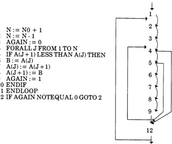
Such
agraph,
as shownin
Figure
2.4,
is
called a spindle.Several
variations of spindles canbe
created,
representing
a number ofdecision
trees
withinthe
program.The
tree
is built
up
ofthese
spindles.One
advantageto this
representationis
that
muchreasoning
aboutprograms
involves
searching
for
pathsthat
exist ordon't
exist.This
searching
normally
canbe
atime consuming
process,
but it
already
has been
taken
careofwith
this
representation.The
trees
areindependent
ofthe
programming
language,
because
they
aresemantic ratherthan
syntactictrees.
There
areafew
operationsthat
Woodpecker
relieson.Woodpecker has
the
ability
to
rename a variablethat originally
was usedfor
morethan
onepurpose,
for
example,
local
variables usedin different
proceduresfor
uniquejobs.
It
may
also permute statementsto
addunderstanding
to the
role of avariable.
This
statement exchange also canbe
appliedto any
two
primary
1
N:=N0
+
1
2
N:
=N-l
3
AGAIN
:=04
F0RALLJFR0M1T0N
5
IF
A(J
+
1
)
LESS THAN
A(J)
THEN
6
B:=A(J)
7
A(J):=A(J+1)
8
A(J+1):=B
9
AGAIN
:=1
10
ENDIF
11
ENDLOOP
12 IF
AGAIN NOTEQUAL
0
GOTO
2
Fig.
2.4
Translating
a simple programinto
a graphorspindle.have been introduced
are replacedby
their
definition
to
improve
the
meaning
ofthe
program.Loops
canbe
suppressed and replaced with a recurrent equation.These
transformation
tools
work well on scalarvariables; arrays,
onthe
other
hand,
are a moredelicate
matter.Another
problemis
recursiveprogramming
languages,
whichlead
to
aninternal
representationthat
is
not afinite
tree.
[image:22.547.86.427.88.373.2]Knowledge is
conveyedto the
Gosseyn
systemthrough
rules,
writtenin
almost naturallanguage.
The left hand
side of a ruleis
a conjunction ofpropositions,
introduced
by
"IF"
or
"FOR ALL". The
righthand
sideis
also aconjunction of
propositions,
with occasional callsto
programmed procedures.The
rulesmay
expressfacts
oropenly
express control.While
rewriting the
programastrees,
anhierarchical
representationis
createdin
aworking
zoneusing
a series of variables and pointers,the
systemthen
usesthis
hierarchical
representationfor
programs,
enabling
it
to
"understand"complex parts ofthe
programit
is
studying.Knowledge-Based
Programming
Support
Tool
While
it
is difficult
to
spanthe
entiredevelopment
of a softwareproject,
the
Knowledge-Based
Programming
Support
Tool
seemsto
cover all possible categories ofthe
process.The
tool
wasdesigned
to
support all aspects ofcoding
withthe
"capability
ofaiding
programmersin
various phases of program production such asdesign,
coding,
debugging,
andtesting"
[HARA85]
.Each
unitthat
wasdeveloped
also canbe
completely
stand-alone.These
various partsinclude:
the
knowledge-based
programming
assistant(KBPA),
the
design
aidunit, the
coding
aidunit, the
testing
aid unit(TAU),
debugging
aidunit,
andthe
knowledge
acquisition unit(KAU). The
interaction
between
these tools
is
shownin Figure 2.5.
The
supervisory
monitor ofthe
KBPA
handles
the
overall system.The
design
aid unitis
aknowledge-based interactive
systemdesign
aidthat
canbe
usedby
system analysts and non-expert systemdesigners
to
constructsoftware systems.
It has knowledge
of schematic systemdesign
and variousdomains
of application.The
design
modelis based
onthe
data flow
diagram
method and conducts a constructivedialogue
withthe
user.A
coding
aid unitprovides a program editor and a
design
coder.Common
data
structures,
algorithms,
and anintelligent
errorrecovery
system are providedby
the
program
editor,
whilethe
design
coderbuilds
programtemplates
corresponding
to the
designed
procedurallayouts.
The
debugging
aid unit operatesboth
on ashallowordeep
level
modelandSupervisory
Monitor
t
a. Ja'1
Knowledge
Acquisition
Unit
Design Aid Unit
^
Coding
Aid
Unit
Debugging
Aid Unit
Testing
Aid Unit
t
t
Knowledge
Base
Figure
2.5.
The
overall structureofthe
KBPA.
situation action rules
for
compile and run-time errors.Situations
representthe
symptomsandthe
facts,
andthe
actions are adescription
ofthe
probablecause
[HARA85], Logic
errors arethe
deeper level
ofdebugging.
Such logic
errors are when
the
programterminates
prematurely,
exceeds run-timeresources,
and proffersincorrect
results.The
program analyzeris
asupportivecomponent
that
providesinformation
onthe
data
andcontrolflow
analysis.
The
knowledge
acquisition unitis
severaltools acting together
to
facilitate
the
acquisition and modification ofknowledge.
As
awhole, the tool
canoperatein
severalmodes: asaconsultant/
advisor,
where
the
user seeksaid,
as aknowledge base
management systemthat
answers
queries,
as atutor
that
provides explanations anddescriptive text,
[image:24.547.131.396.74.402.2]Expert
System
I
Application Generator
The ES/AG (Expert System
/
Application
Generator)
is
a softwareengineering
environmentfor
the
construction ofintelligent
applicationsystems
[CRON85].
It
also coversthe
range ofthe
entiredevelopment
of a softwareproject, especially
generationtools
and run-time problemsolving
tools.
The
generationtools
consistlargely
of afirst
level AL
(A-Level)
compiler,
which readsthe
applicationterminology
componentanddetermines
attributes
to
be
associatedwiththe
symbols andrules,
and a secondlevel
(SL)
compiler,
which reads an application specificknowledge
base,
creates code and ruleactions,
and extractsinformation
onthe
problemsolving
model structure.Semantic
validation ofthe
attributesand value associationsto the
symbols are provided.The
generationtools
also allow queriesto
comeinto
the
knowledge base
in
aformatted display.
Run-time
problem-solving tools
arebroken
up
into
several categories.Non-procedural
control strategieskeep
track
ofthe
state ofthe
problem-solving
process,
forward
andbackward
chaining,
andbacktracking
in
two
phases.Phase
oneis
the
invocation
of procedureblocks,
and phasetwo
is
the
selection andinvocation
of rules.Explanation
tools
help
providethe
construction ofdynamic dependencies
during
backward
chaining
and canbe
usedto
providethe
reasonsto
a question of'why'.
A
userinterface
to
the
problem-solving
modelthrough
the
userdialog
module provides a set of capabilitiesfor
the
end-user andit
allowsquestions,
input
valuevalidation,
default
values,
help
ability,
string
construction,
and output routines.A
retrieval ofapplication-attributeknowledge
enables run-time access ofattribute
knowledge from
aknowledge base
and user-direct control ofknowledge
retrieval.There
is
aninterface
to
the
user-supplied programcomponents,
which canbe
connectedto easily
integrate
user-suppliedcomponents
to existing
software.An interface
to two
Lisp
interpreters,
XLisp
andFranz
Lisp,
allows callsto
be
included
withinthe
specifications.A list
processing
moduleis
provided with a set of routinesto access,
change and create values oflists
orlist
elementsto
avoidthe
overhead of afull
LISP
Approximate
string matching is
also provided with automatic recognition ofabbreviations or misspelled
information
enteredby
the
end-user,
with a choice ofpossible replacementsfor
the
string.2.1.3
Related
Xerox
Projects
While
none ofthe
Xerox
tools
or articles reviewedbelow incorporate
artificial
intelligence,
many
ofthem
are usedin
the
current softwaredevelopment
process.The
softwaredevelopment
processhas
undergoneupgrades and
reviews,
which werediscussed
in
section1.2.
Some
ofthe tools
used
in
this
process willbe
reviewedin
depth
below,
specifically
the
System
Modeler, DFTool,
andRelease Tool.
A
base
referencefor
the
softwaredevelopment
stepsin
preparing
alink
reliesheavily
onthe
Describe File
Tool
software
(DFTool)
[HOWT085].
The System
Modeler
Xerox's Computer Science
Laboratory
atPalo Alto Research Center
(PARC)
has developed
aSystem
Modeler
for
adistributed
environment[LAMP83],
which provides automatic supportfor
severaldifferent kinds
ofprogram
development
cyclesin
the
Cedar
programming
environment.It
usesinformation
storedin
a system modelthat
describes
the
versions of variousfiles,
the
interconnections
between
files,
any
additionalinformation
neededto
compile and
load
the
system,
andhints
onthe
locations
ofthe
files
needed.The
Modeler
is
capable of avariety
of operations onthe
system.It
implements
the
representation ofthe system, tracks
changes madeby
the
programmer,
automatically
builds
an executable version ofthe system,
and provides complete supportfor
the
integration
of packages as part of a release.To facilitate
the
interaction
withthe
various machines andfile
services,
the
Modeler
maintains severalfiles
that
facilitate
reduced searchandcompiletimes.
The
top
modelis
alist
ofmodelsandthe
file
serveranddirectory
whereeach can
be located.
An
objecttype table
andprojectiontable
are acceleratorsfor
the
Modeler,
providing
alist
of objecttypes
and entriesrequiring
recompilation
for
the
nextiteration
ofthe
system.Two
types
ofdelays
existin
such a
distributed
environment.First,
if
the
file is
on a remotemachine,
it
The Modeler
provides a wellintegrated
systemfor
adistributed
environment.
It
handles
versioncontrol,
remoteinteraction
with othermachines and
file
servers,
retrieval ofneededfiles
from
these
remotedevices,
storage ofthe
resulting
compiledsystem,
and creation of a release ofthe
specified system model.
Although it does
nothandle
the
diagnosis
of possibleerrors
in
each ofits
operations, the
Modeler
utilizesthe
distributed
environment
to
its full
advantage.Describe File Software Tool
-DFTool
The Describe File
softwarehas
the
ability
to
describe
the
version andlocation
offiles,
relieving
the
user ofneeding
to
know
wherethe
files
arelocated
andwhich versionsofthe
files
to
use.A
singledescription
file,
orDF
File,
may
describe
all requiredfiles
in
a program.Thus,
the
name ofthat
DF
File
couldbe
usedsimply to
bring
over allfiles
neededto
work on a specificprogram.
After
those
files have
been
modified, the
DF
program will storeback
only
those
files
that
were changed.Importing
andexporting
of explicitfiles
allows
for
carefulsharing
ofprogramsbetween implementors.
Describing
asoftware system with a
DF
file
enablesthe
use ofthe tools
for
managing
files,
verifying
programconsistency,
andallowing
programsto
be
a part of a major software release.Four
ofthe
most usedDF
(describe
file)
programs areBringOver,
SModel,
VerifyDF,
andDFTool.
BringOver
retrievesthe
files listed
in
aDF
file from
their
remotefile
servers,
possibly overwriting
different
versionsalready
onthe
local disk.
It insures
that
allfiles for
acomponent,
andthe
correctversionsof
those
files,
are onthe
local
disk.
SModel
stores changed versions offiles
back
on remotefile
servers and produces a newDF
file
containing
referencesto
the
newest versions.Normally,
the
newDF
file is
also storedremotely
for
use
by
clients ofthat
component.VerifyDF
checksthat
aDF
file is
complete andconsistent,
that
is,
that
allfiles
neededto
build
the top-level
objectfiles
of a component arelisted in
the
DF
file
and are consistent with regardto the
Mesa
compiler andbinder.
DFTool
provides a windowinterface
to the
otherThe DF file
that
accomplishesthese
functions
usually
has
three
sections:the
interface
orimplementation
files
neededby
the client, the
list
offiles
that
comprise
the component,
andthe
imported
files
neededto
build
the
component.
The files
exportedby
the
DF
software are markedby
the
keyword
Exports;
otherfiles
that
are partofthe DF
file
are markedwithDirectory;
andthe
imported
files
have
the
keyword Imports.
An
example of aDF
file is
included
in
Appendix A.
A
standard use ofthe
DF
programsfor
a specificmodule
follows
abasic
sequence:BringOver
the
DF
file
to
insure
that
allfiles
needed are on
the
local disk in
the
correctversion;
modify
andtest the
files;
SModel
the
DF
file
to
storeback
the
changedfiles
and updatethe
DF
file
to
reflect
the
newversions;
VerifyDF
ofthe
DF
file
to verify that the
files
arecomplete and consistent.
This last function is
not oftenused,
causing
problems
to
go unnoticed untilthe
link. These basic
programsalong
with aspecifiedset of options provide a sound
basis for
versionchecking
and changecontrol
for
a multi-user software project.A DFTool Example
One
Xerox
softwaregroup
took
it
uponitself
as a projectto
develop
asystem
that efficiently
createdabasic
file
management system[FILE86]. The
project report provides a clear
definition
ofthe
contents of a software packagereleased
for
test.
The
system wasdivided into
three
parts:the
creation andstorage of a
link,
the
storage ofa recent release andeveryday
links,
andthe
backup
of oldreleaselinks.
The first
part ofthe
report,
which coversthe
creationand storageofalink,
utilizes
the
Describe File
tool
(DF
Tool)
andhelps
to
explainbetter
the
necessary information
for
correctly monitoring
module versions[FILE 86].
Instruction
is
also providedfor
floppy
archival storage ofsoftwarereleases,
including
the naming
of revisions.A
versiontracking
systemwasinstalled
to
allow
for
a check-in and check-out of allfiles
withinthe
release.Such
alibrarian
system prevents simultaneous changesto
a singlefile, thereby
eliminating
revisionediting
problems.Another
Extensive
DFTool Application
Within
Xerox's Office Systems
Division,
the
Mesa
group
implemented
the
implementation
provedto
be
very
effective
for managing
versions of softwarein
their
distributed
programming
environment.
It
wasused
to
assistin
the
development
ofthe
last
version ofthe
Xerox
Development
Environment,
which
included 501,442 lines
ofMesa
codein 5360
files
[LEWIS].
Version
control withinthis
environment was a problem since eachprogrammer workedon a separate
Xerox Workstation linked
by
anEthernet
connection.
Locating
the
correct versions offiles
in
this
network was adifficult
problemfor
programmers.Developers
wouldexplicitly copy
files
between
their
workstationsto modify, compile,
build,
andtest their
software.Mesa
also usedboth interface files
andimplementation files
to
constructits
components.
The
use ofthe
DF
system withinthis
processprovided away
ofchecking
the
correct versionsof eachnecessary
component.In
the past, the
Mesa
group
managedthe
software withthe
use ofthree
software
tools:
FTP, MakeA,
andInclude Checker.
FTP (File Transfer
Program)
transfers
files
overthe
Ethernet between
the
local
disk
and aremote
file
server.FTP
has
an optionto
retrieve or storeonly
newerversionsof
files. MakeA
generatescommandfiles
that
do
the
retrieve-build-store stepsfor
rebuilding
a component.MakeA
executes a scriptfile
writtenfor
the
component.
These
scripts are programsin
a simplelanguage
that
includes
variables,
conditionalstatements,
and primitivesfor
interacting
withthe
user.
A
MakeA
scriptcanbe
parameterizedto
allowthe user,
for
example, to
build
all oronly
part ofthe
component.The location from
whichfiles
areto
be
retrieved also can
be
aparameter,
allowing
the
userto
build
privateversionsof
the
component.IncludeChecker
checksa setofMesa
source and objectfiles for
consistency.It
canbe
usedto
checkthe consistency
ofa single software component or anentire release.
It
also can checkboth local
and remotefiles.
The
IncludeChecker
also will generate a compiler andbinder
commandthat
willdo
any rebuilding
necessary to
makethe
collectionoffiles
consistent.Despite
care, this
system still allowedmistakes, the
cost of which wasfiles
notbeing
stored,
difficulty
in retrieving
otherthan the
most recentversions,
and extensivetime
requiredfor
IncludeChecker.
Difficulties
were encountered withDF
softwarein
the early
stages ofimplementation.
These
difficulties
stemmedfrom
the
lack
of practicesthat
needed
to
be developed fo