DESIGN OPTIMIZATION ON
POWER TRAIN SYSTEM FOR FIRE FIGHTING MACHINE
OMAR ABDULLAH @ BONNY LU HIENG SIONG
i
‘I/We* have read this thesis and from my/our* opinion this thesis
is sufficient in aspects of scope and quality for awarding Bachelor of Mechanical Engineering (Automotive)’
Signatures : ………..
Name of Supervisor I : Mr. Mohd Zakaria Mohammad Nasir
Date : ………..
Signatures : ………..
Name of Supervisor II : Mr. Razali Mohd Tihth
Date : ………..
ii
DESIGN OPTIMIZATION ON
POWER TRAIN SYSTEM FOR FIRE FIGHTING MACHINE
OMAR ABDULLAH @ BONNY LU HIENG SIONG
This report is presented in
Partial fulfillment of the requirements for the Bachelor of Mechanical Engineering (Automotive)
Faculty of Mechanical Engineering Universiti Teknikal Malaysia Melaka
iii
“I declare this report is on my own work except for summary and quotes that I have mentioned its sources”
Signature : ………..
Name of Author : ………..
iv
Dedicated to my beloved mom and dad, thank you all for all that you have done. Hard times are now turned into times of pride. I have gone through so many different stages changing ideas and goals while searching for the right kind of life for me. You
were always ready to help me at all times. It must have seemed like I would never follow one straight path. Now that I know what I am doing and where I am going I can only show you my extreme appreciation for your support by being true to all the ideals and values that you tried to teach me. Thank you forever for standing by me. I love and appreciate you forever. May Allah S.W.T bless you with happiness and give
v
ACKNOWLEDGEMENTS
Assalamualaikum W.B.T. First of all, I would like express my gratitude to my supervisor, Mr. Mohd. Zakaria Mohammad Nasir on his support from every aspect throughout the completion of this PSM report. Without his guidance, I would not be able to handle this project wisely.
I also thank to my family for being supportive from many aspects to let me complete this project. Not to forget, thanks to my fellow friends for being kind to offer me such help in many ways and knowledge.
vi ABSTRAK
vii ABSTRACT
viii
TABLE OF CONTENT
CHAPTER TITLE PAGE
PREFACE ii
DEDICATION iv
ACKNOWLEDGEMENT v
ABSTRAK vi
ABSTRACT vii
TABLE OF CONTENT viii
LIST OF TABLES xi
LIST OF FIGURES xii
LIST OF SYMBOL xvi
LIST OF EQUATIONS xvii
LIST OF APPENDICES xix
NOMENCLATURE xx
I INTRODUCTION 1
1.1 Project Significant 2
1.2 Problem Statement 3
1.3 Objective 4
ix
CHAPTER TITLE PAGE
II LITERATURE REVIEW 5
2.1 UTeM’s Fire Fighter Machine 6
2.2 Existing Fire Fighter Machine in Market 2.2.1 ARMTEC's SACI Firefighting Robot 2.2.2 Rainbow 5
8 8 9
2.4 Parts and Components 10
2.5
2.4.1 DC Motor 2.4.2 Pulleys and Belts
2.4.3 Sprockets and Roller Chain 2.4.4 Chain versus Drive Belts
2.4.5 Wheel Diameter, Torque, and Speed 2.4.6 Tank Track
2.4.7 Tank Track Skid Steering 2.4.7.1 Dual Drive 2.4.7.2 Clutch-Brake 2.4.7.3 Geared Steering 2.4.7.4 Braked Differential
2.4.7.5 Cletrac or Controlled Differential 2.4.7.6 Maybach Double Differential
2.4.7.7 Double Differential 2.4.7.8 Triple Differential Study Analysis
2.5.1 Advantages
10 12 14 15 17 18 22 23 23 25 26 27 28 29 30 32 32
III METHODOLOGY 33
3.1 Process Flow Chart for PSM 34
3.2 Concept Design 35
3.2.1 Design 1: Dual Motor Drive 36
3.2.2 Design 2: Clutch Brake System 38 3.2.3 Design 3: Toroidal CVT System 40
x
CHAPTER TITLE PAGE
3.4 Concept Scoring Matrix 44
3.5 Motor Controller 45
3.5.1 Robot Power Sidewinder 45
IV DETAIL DESIGN 47
4.1 Electric DC Motor 48
4.2 Pulley and Belt Selection 50
4.2.1 Pulley 51
4.2.2 Belt 53
V DESIGN ANALYSIS 61
5.1 Motor frame 63
5.1.1 Analysis on Motor Frame 65
5.2 Beam ‘A’ 69
5.2.1 Analysis on Beam ‘A’ 70
5.3 Beam ‘B’ 74
5.3.1 Analysis on Beam ‘B’ 75
5.4 Beam ‘C’ 79
5.4.1 Analysis on Beam ‘C’ 80
5.5 Drive Shaft 84
5.5.1 Analysis on Drive Shaft 86
5.6 Chassis 89
5.6.1 Analysis on Chassis 91
VI RESULT AND DISCUSSION 96
6.1 Result Analysis 96
6.2 Effect of the Analysis 97
VII CONCLUSION 98
7.1 Conclusion 98
xi
CHAPTER TITLE PAGE
REFERENCES 100
BIBLIOGRAPHY 101
xii
LIST OF TABLES
TABLE TITLE PAGE
2.1 Speed test in 5 meters 7
2.2 General specifications of the UFFM 7
2.3 Comparisons between chain and belt 15
2.4 Time elapsed for the UFFM to steer at certain angle 31
3.1 Comparisons for each design 43
3.4 Concept Scoring Matrix 44
4.1 NEMA Design B, Single speed 1200, 1800, 3600 rpm 48
4.2 Pulley size and speed 52
4.3 General specifications of the UFFM 53
4.4 Characteristics of common belt types 59
xiii
LIST OF FIGURES
FIGURE TITLE PAGE
1.1 UTeM’s Fire Fighter Machine 2
1.2 The UFFM’s motor and drive train 3
1.3 UFFM’s heavy duty rubber track belt 4
2.1 Side view of UTeM’s Fire Fighter Machine 6
2.2 ARMTEC’s SACI putting out fire 8
2.3 Japanese Rainbow 5 9
2.4 V-belt and flat pulley 12
2.5 V-Belt drive conventional frame 12
2.6 Silicone coated belts 13
2.7 Nylon conveyor belt 13
2.8 Chain roller sprocket 14
2.9 Roller chain 14
2.10 Real tank track 18
2.11 Tank track components 19
2.12 Adding bogies to tracks 20
2.13 Wheel rollout 21
2.14 The UFFM track assembly 21
2.15 Skid steering frictional forces magnitude 22
2.16 Clutch brake steering diagram 24
xiv
FIGURE TITLE PAGE
2.18 Braked differential steering diagram 26
2.19 Controlled differential steering system 27
2.20 Maybach double differential steering 28
2.21 Double differential steering diagram 29
2.22 Triple differential steering 30
2.23 Small trackwidth tank track skid steering 31
3.1 Flow of case study 34
3.2 Main frame of the UFFM 35
3.3 Top view of the UFFM using dual motor drive 36
3.4 Dual motor setup 36
3.5 Top view of the UFFM using clutch brake system 38
3.6 Clutch brake mechanisms 39
3.7 Top view of the UFFM using Toroidal CVT system 40
3.8 Motion in straight line 41
3.9 Steer to the right 41
3.10 Steer to the left 41
3.11 Sidewinder front panel controls and LED indicators 46 3.12 Sidewinder rear power leads and grommets in the enclosure
rear plate
46
4.1 Motor mounting 47
4.2 Sanpo motor 48
4.3 CAD of electric motor 48
4.4 Pulley and timing belt positioning on Design 1 50
4.5 Free Body Diagram of pulley system 54
4.6 Centrifugal force 59
5.1 Main frame with dual motor mounting 62
5.2 Motor frame with slotted bracket 63
xv
FIGURE TITLE PAGE
5.4 Rear view 64
5.5 Top view 64
5.6 Constraints on the slotted bracket 65
5.7 Loads acting on the slotted hole 66
5.8 Stress distribution 66
5.9 Displacement distribution and deformation 67
5.10 Factor of Safety of the motor frame 67
5.11 Beam ‘A’ 69
5.12 Rear view 69
5.13 Side view 70
5.14 Constraints on both ends and hollow beam 71
5.15 Loads acting on screw mountings 71
5.16 Stress distribution 72
5.17 Displacement distribution and deformation 72
5.18 Factor of Safety of beam ‘A’ 73
5.19 Beam ‘B’ 74
5.20 Rear view 74
5.21 Side view 75
5.22 Constraints on joints 75
5.23 Loads acting on screw mountings 76
5.24 Stress distribution 76
5.25 Displacement distribution and deformation 77
5.26 Factor of Safety of beam ‘B’ 77
5.27 Beam ‘C’ 79
5.28 Rear view 79
5.29 Side view 80
5.30 Constraints on joints 80
5.31 Loads acting on screw mountings 81
5.32 Stress distribution 81
5.33 Displacement distribution and deformation 82
xvi
FIGURE TITLE PAGE
5.35 Final drive shaft 84
5.36 Side view 85
5.37 Constraint on track joint 86
5.38 Torque acting on drive shaft mounting 86
5.39 Stress distribution 87
5.40 Displacement distribution and deformation 87
5.41 Factor of Safety of drive shaft 88
5.42 Chassis with motor frame 89
5.43 Chassis side view 90
5.44 Chassis rear view 90
5.45 Chassis top view 91
5.46 Constraints on the slotted bracket 92
5.47 Loads acting on the slotted mounting 92
5.48 Stress distribution 93
5.49 Displacement distribution and deformation 93
xvii
LIST OF SYMBOLS
ω = Angular speed, rad/s
N = Rotational speed per minute, RPM
P = Power, W
T = Torque, N.m
V = Electromotive force/voltage, V
I = Current, A
η = Efficiency
xviii
LIST OF EQUATIONS
EQ. ELEMENTS UNIT
2.1 Angular Speed, rad/s
2.2 Power, Watt 2.3 Distance, D = πd m
xix
EQ. ELEMENTS UNIT
4.12 ω = γbt N/m3 4.13 Centripetal force, Fc = (w / g).V2 N 4.14 Torque, T = (Hnom.Ks. nd) / 2πn Nm 4.15 Allowable force, F1 – F2 = (2T) / d N
xx
LIST OF APPENDICES
NUM. TITLE PAGE
A Gantt Chart 104
B Chassis 106
C Motor Frame 109
D Support Beam 112
E Drive shaft 116
xxi
NOMENCLATURE
UFFM N/A
UTeM’s Fire Fighter Machine Not Available
CAD Computer-Aided Design DC Direct Current
R&D RPM CVT ICE PDA
Research & Development Revolutions per Minute
Continuously Variable Transmission Internal Combustion Engine
Personal Digital Assistant
1
CHAPTER I
INTRODUCTION
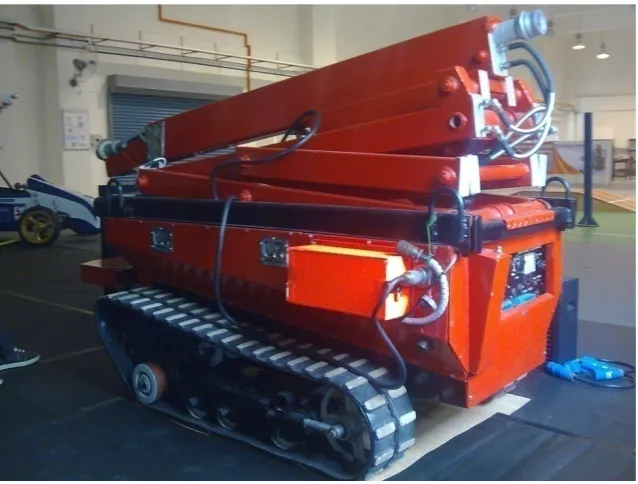
In 2007, UTeM has developed its very own fire fighting machine under the Faculty of Mechanical Engineering, in collaboration with local engineering company, Ritz Power Mechanics Sdn. Bhd.. Named as ‘UTeM Fire Fighter Machine’, the machine is controlled via radio frequency control, which allows the operator to send the machine to potential site while the operator stays at the safe site. This research helps the firemen to put out fire in high risk areas like factory, forests and war site. Many dangerous tasks can be solved and firemen’s life can be secured by using the UFFM.
2
Figure 1.1: UTeM’s Fire Fighter Machine