International Journal of Innovative Technology and Exploring Engineering (IJITEE) ISSN: 2278-3075, Volume-8, Issue- 9S2, July 2019
Abstract— Hybrid features batteriesand photovoltaic (PV) module located on the roof of electric Vehicles (EV) can be effectively used by a single stage interaction converter (SSIC). SSIC is introduced for directing the energy flow amid the PV panel, battery and BLDC machine.In this paper a novel braking system is used for charing electrical vehicles using solar battery system (PV) integrated with BLDC motor. It is called as RBS (Regenerative Braking System). During the RB process, generator function is provided by BLDC motor. In order to boost the BLDC-Back-EMF, a suitable switching algorithm is used. By boosting the inverter and SSIC converter the DC-Link voltage reference is reduced to charge the battery. It increases the efficiency of the RB system. In this paper Aritifical Neural Network is used to provide a smooth and reliable brake with distributed force. This proposed BLDC-Back-EMF is experimented in MATLAB Simulink software and the results are verified. Speed, Breaking-Force, torque and front-RB force, rear-meachnical-RB force and other voltage, power are verified.
I. INTRODUCTION
In recent days charingclectrical vehicles (EV) is higly connected with solar PV stations where it is one the promising energy generation method. Solar PV system plays a major role in the electricity market and it is one of the promising technology in power generation. Due to high consumption and demand of fuel, transport industry require a modified vehicle with less fuel consumption that is EV. EVs are considered as a potentially good element for future transport. By using EVs it is very easy to control the fuel demand and provide a better transport in world. In terms of power generation solar PV has been proving its ability in high power generation under renewable energy resources. It has great potential in contributing major power generation by challenging electricity supply under various environmental conditions. Regarding cost, PV grid installation technology is not high comparing with the other renewable energy sources. In recent days PV deployment throughout world is continuously growing rapidly. In electricity industrial point of view, EVs increased their demand in absolute CO2 emission [1]. Solar based charing EVs is gaining more attention, because it has more advantages like less emission, quite operation and improved efficiency etc. [3,4]. Due to the development of motor technology and battery [5], charing EVs using renewable
Revised Manuscript Received on July 18, 2019.
Mr.S.Jambulingam, Electro Technical Officer,Coimbatore Marine College,Coimbatore,Tamilnadu, India.(Email : [email protected]@gmail.com)
Dr.D.M. Mary Synthia Regis Prabha,Department Of Electrical And Electronics Engineering, Nooru Islam University, Kanyakumari, Tamilnadu,India.
energy system, especially PV, becomes most promising alternative to the available fuel. Different technoloiges have been used for charging various kinds of vehicles, but they have only limited capacities of charing batteries. Hence, charing EVs are till having problem because suffering from shorter distance driving comaring with normal fuel vehicles [6]. In order to improve the performance of PV based charing EVs, silicon PVs are introduced with less price and motivated to encouraring more number of people to use PV based EVs [7-8].
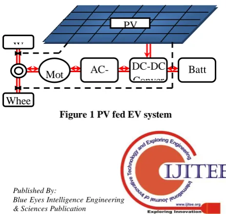
[image:1.595.313.545.613.832.2]Several earlier research works have been carried out to get more efficiency and controlled BLDC [9-10]. A considereable amount of research works have been proposed to integrate EVs and BLDC motors [11-13]. In EV’s application where BLDC motor is adopted as the main driving source, the kinetic energy in deceleration process can be converted into the electrical one and recovered by enforcing BLDC working as an alternator to recharge the energy storage device (batteries or super capacitors). In principle, the so-called RGB method utilizes the back electromotive force (BEMF) to generate the opposite torque to brake. At present, researchers have proved that RGB method is efficient to improve the braking performance and extend the driving range without any additional cost. Author in [14] stated that RGB method provides a best battery topology [14] where it directly connects the battery and DC-Link. Atuhor in [15] discussed about ESSs for more power converter included in charing EV system with cost efficiency. To improve the power flwo to both capacitor and battery using a bidirectional DC-DC converter. For example Figure-1 shows the overall architecture of PV based EV system. In this PV panel is directly connected with converter and wheel bus.
Figure 1 PV fed EV system
ANN Based Improved Regenerative Braking
System on PV/Battery Powered Electric
Vehicles with Single Stage Interaction
Converter
S.Jambulingam, D.M. Mary Synthia Regis Prabha
VEHICLES WITH SINGLE STAGE INTERACTION CONVERTER
[image:2.595.58.289.239.398.2]Regarding power electronics, two main topologies are used in the power converter. One is inverter and the other one is DC-DC converter. However, an effective topology and RGB method for PV-fed EV’s are not yet industrialized. Because the PV has dissimilarfeatures to ICEs, the supreme power point tracking (MPPT) and solar energy utilization are the unique factors for the PV-fed EV’s. One of the obejctives of this paper is to reduce the less cost based flexible energy by integrating PV, battery and motor. During the process of braking the switching algorithm is used inverter, and voltage booster. The energy for braking system is supplied by the battery and SSIC convereter. The propsoed ANN -RGB technology is used for improving the braking performance in EV.
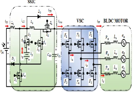
Figure 2 Equivalent circuit of the proposed PV fed EV system
II. PROPOSED EV SYSTEM AND SUPPORTED OPERATING MODES
In Figure 2, the structure of the proposed PV fed EV is depicted. It comprises of PV, battery, SSIC, Voltage Source Converter (VSC), and a BLDC motor. A SSIC is presented for managing the power flow amid PV, battery and EV motor correspondingly. A PV and battery is associated to the dc-link via SSIC and therefore, the dc-link voltage is comparatively constant. Likewise, SSIC is used to supply the BLDC motor through the VSC. For the duration of motor mode, the VSC performs like an inverter to drive the BLDC machine with six-step commutation, which is attained by directing the order of conduction on the MOSFET’s in VSC. If we need to direct a BLDC motor, we should recognize the place of the rotor that identifies the commutation. For identifying the rotor position, Hall-effect sensors are the generally utilized sensor. For the duration of the vehicle braking, the BLDC machine works like a generator. So, by using the MOSFETs in the VSC and the motor inductances and also by agreeing an appropriate switching pattern, a boost chopper is created. So, for the period of the braking process, the regenerative energy is stored in the dc-link. The dc-link voltage is attuned via duty-cycle deviation of MOSFET’s in the SSIC. Therefore, the dc-link energy is reaped by the battery pack with the proposed SSIC successfully.
In Figure 3(a),the three-phase BEMF’s ( ), three-phase stator currents ( ), Hall-effect signals
( ) and the appropriate switching patterns are depicted. Six commutation intervals are there n the motor mode and two of the VSC switches is turned “ON” and “OFF” for the duration of every interval. In Figure 3(b)., the corresponding circuit for one commutation state (240° − 300°) of the motor mode with battery is depicted. In the RGB mode, six commutation intervals are there and just one among the VSC switches is turned “ON” and “OFF” for the period of each interval. In Figure 3(c), the correspondent circuit for one commutation state (0° − 60°) of the RGB with battery is depicted. In Figure 3 (b) and (c),
are the inductance and induced voltage of the armature, correspondingly. For a complete electrical cycle of the RGB process, every switch is modulated inside 120 electrical degrees. For that reason, the vehicle’s braking energy is transformed into electrical energy that evades the waste of energy, elongate the battery life, and improve the driving range.
International Journal of Innovative Technology and Exploring Engineering (IJITEE) ISSN: 2278-3075, Volume-8, Issue- 9S2, July 2019
Figure 3 The waveforms of the BEMF’s, stator currents, Hall-effect signals and the switching pattern
(a) Motor and RC mode, operational behavior of the VSC under (b) motor mode at (240° − 300°) (c) RC
mode at (0° − 60°)
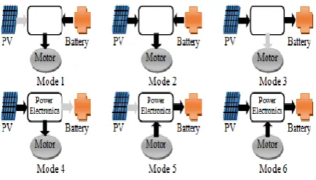
[image:3.595.60.283.571.697.2]As depicted in Figure 4, by directing SSIC, the six operation modes are assisted in EV. The battery supplies power to the BLDC motor; the system works in mode 1, while the PV could not produce electricity because of less solar irradiation. The PV as well as battery supply power to the BLDC motor; the system works in mode 2,while the BLDC motor works in heavy load for instance uphill driving or acceleration,. The PV could charge the battery; the system functions in mode 3, while the EV is parked underneath the sun. PV is the only energy source to activate the EV while the battery is down; the system functions in mode 4. For the period of braking process, RGB technique could charge the battery; the system functions in mode 5. PV and RC technique could charge the battery in mode 6.
Figure 4 Supported operating modes in proposed EV system
III. WORKING PRINCIPLE OF SSIC UNDER MOTOR MODE
The control system obtains a drive signal via the activation of the accelerator, therefore BLDC machine is
VEHICLES WITH SINGLE STAGE INTERACTION CONVERTER
[image:4.595.61.282.71.696.2]Figure 5 Current flow analysis of the SSIC during different intervals at motor mode
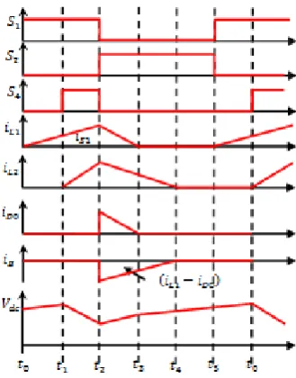
Figure 6 Associated key waveforms of SSIC at motor mode
For the period of this interval [Figure 5(a)], the switches are on, when the switch is off. Presently, input inductor is charged in a linear manner by the PV voltage and input inductor is charged in a linear manner by the battery through ant parallel diode . So, the inductors current rises in a linear manner as depicted in Figure 6. For the period of this interval
[Figure 5(b)], the switch is on, when the switches
are off. The inductor is still charged in a linear manner by the PV voltage, in the meantime the dc-link capacitor is charged by the inductor via antiparallel diodes .
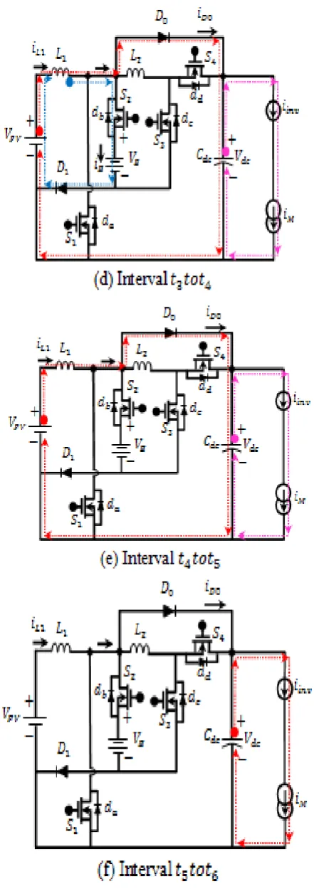
For the period of this interval [Figure 5(c)], just the switch is on, when the switches are off. The PV and inductors current dischrges via antiparallel diode to transmit its energy to the dc-link capacitor . Therefore in this mode the inductors current reduces in a linear manner as depicted in Figure 6. In interval [Figure 5(d)], the diode and switch are in conduction; therefore the energy stored in inductor is transformed to and battery, correspondingly. In this mode of operation [Figure 5(e)], the output diode is still forward biased; therefore the inductor is totally discharged and its current turn out to be zero as depicted in Figure 6. For the period of this interval [Figure 5(f)], the diode is stops conducting; therefore the dc-link capacitor provides energy to the BLDC motor via VSC. According to Figure 5(a)-(f), PV and battery ports are controlled via SSIC and for keeping continuous supply to the EV is examined.
IV. WORKING PRINCIPLE OF SSIC UNDER RGB MODE
International Journal of Innovative Technology and Exploring Engineering (IJITEE) ISSN: 2278-3075, Volume-8, Issue- 9S2, July 2019
[image:5.595.323.544.57.420.2]The key of the technique is to direct the charging voltage/current from motor to battery through the control the SSIC. In this RGB mode switch is altogether off state and its related waveforms in an exchanging period as appeared in Figure 8.
[image:5.595.344.509.468.678.2]Figure 7 Current flow analysis of the SSIC during different intervals at RC mode
Figure 8 Associated key waveforms of SSIC at RGB mode
VEHICLES WITH SINGLE STAGE INTERACTION CONVERTER
voltage. Consequently, the inductor current rises directly, as appeared in Figure 8. Amid this interval [Figure 7(b)], the switches are on. The inductor is as yet charged directly by the PV voltage, in the mean time the inductor is charged by the dc-link capacitor by means of and henceforth inductor current increments linearly as appeared in Figure 8. In interval [Figure 7(c)], basically the switch is on, while the switches
are off. In this manner, inductors and current charges the battery by means of diode and antiparallel diode , separately. Consequently in this mode the inductors and current abatements and battery current increments linearly as appeared in Figure 8. In interval
[Figure 7(d)], the ant parallel diode is still forward biased; subsequently the inductor is totally released and its current winds up noticeably zero as appeared in Figure 8. In this interval [Figure 7(e)], the regenerative current of BLDC machine energies the dc-link capacitor
From Figure 7(a)- (e), PV and regenerative energies are regulated through SSIC and to keep up continues supply to the EV is investigated.
V. CONTROL STRATEGY OF PROPOSED EV RBS
Based on ANN the force is distributed for the braking operations. The main portion of the propsoed method is carried out by SSIC controller. The overall structure of the proposed system is explained below.
1) The braking force distribution:
During braking, kinetic energy of the EV will be transferred to the battery. In some braking occasions, the battery will reach its maximum capacity and it cannot accept further charge from the BLDC machine, which limits the regenerative capability. Therefore, involvement of mechanical (frictional) braking is critical for accomplishing the braking objective. Through the pedal sensor, we can obtain the driver's required braking force. Hence, the total braking force ( ) of the EV is composed of the rear ( ) and front ( ) braking forces:
(1) (2) (3) (4)
In (2) and (3), is the height of the centroid of the EV, is the air density (kg/m3), is the drag force coefficient,
is the frontal area of the vehicle (m2), v is the vehicle linear velocity ( ), is the centroid of the vehicle to the front axle centerline distance, is the centroid of the vehicle to the rear axle centerline distance, is the adhesion coefficient, is the vehicle load, is the gravitational
constant, and is the distance from rear axle to the front axle of the EV ( ). Moreover, is defined as
in which is the acceleration of the vehicle.
Height of the centroid of the EV is created by the gravity which substantially affects the behavior of the vehicle. The Height of the centroid ( can be expressed as.
(5)
Where is the slope angle (degree).
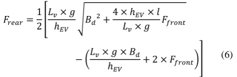
The maximum braking force that can make the rear and front wheels lock simultaneously for every possible adhesion coefficient can be obtained using:
(6)
[image:6.595.309.546.202.279.2]Solving (1) and (6) yields the required braking force at the rear and front wheels of the vehicle. In this paper, the weight of the EV including cargo and HESS is 85 kg. Other parameters of the EV are listed in Table 2.
Table 1. PARAMETERS OF THE EV AND THE ROAD CONDITIONS
2) The ANN controller
International Journal of Innovative Technology and Exploring Engineering (IJITEE) ISSN: 2278-3075, Volume-8, Issue- 9S2, July 2019
EVs incorporated solar PV has more implementation complexity. In to overcome that, this paper proposed ANN based controller for braking systems in EVs. One of the machine learning and intelligent computing methodology is ANN, where it comprises of various compoenents, layers, nurons and able to control the relationship among all I/O patterns [16-17].
The performanc of ANN is depending on its structure. Initially a defined dataset is divided into two portions for training and testing process. On the training process ANN learn the major portion of the data and prepare a conclusion. Then the learned features are feed into the number of hidenlayers . Each has more number nurons where each nuron can do a predefined taks. Then trained ANN is evaluated using other datasets to check the accuracy in generalization. Also, multiple simulations is carried out on four layered MLP-NN and is compared with ANN performance. SOC of the battery, speed, power of PV and depression of brake speed are input into ANN’s input layer. All the hidden layers match the features extracted and choose the best features for calculating the force. To do this Sigmoid function is used as an activation function in the hidden layers and it is written as:
(7)
[image:7.595.312.549.330.575.2]Similarly, a linear function is used for calculating the output in the output layer. The structure of ANN is depicted in Figure-9, where is has input values in the input layer, hidden layers and outputs from the output layer.
Figure 9 Structure of ANN Network
The proposed ANN is experimented in
MATLAB/Simulink software on training, testing dataset and the results are verified. Simulation is executed more number of times by changing the SOC – battery values and PV power to obtain optimal output. According to the speed and other parameter values the brake strength is investigated. Braking scenarios can be created by selecting the best drive cycle in the simulation. Each scenario has different speed of EV and brake strength. Finally a trained model is obtained from the training process. Appendix – A shows the training process specifications. Braking force calculation is done in accordance to the following criteria as:
1)The Vechicle is decelerated or stopped in the specified and the time determined by the drive cycle
2)maximum regeneration is achieved
3)SOC of battery remain within the safe margins.
3) Controller Control Strategy Of Ssic:
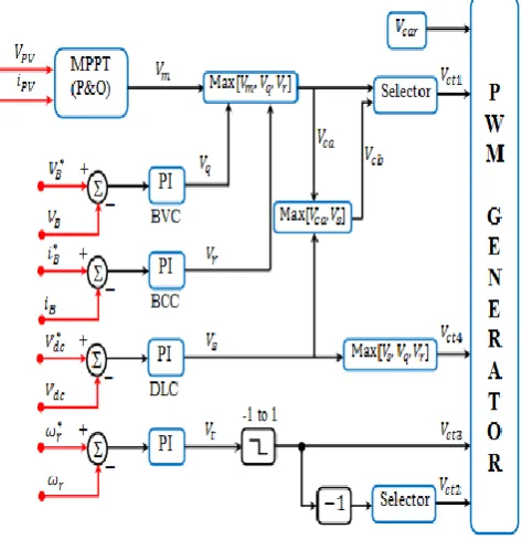
[image:7.595.57.288.416.553.2]Figure 10 shows the control diagram and modulation method for the proposed SSIC converter, where is the output of MPPT algorithm (using Perturb & Observe method [18],For regulating EV parameter (voltage, current, and speed) the actual value is measured and compared with a reference value; later the voltage difference, or regulation error, is amplified according to proportional and integral gains of the regulation controllers (RC), which delivers a control voltage. Four RC’s, battery voltage controller (BVC) for maximum voltage charging control, battery current controller (BCC) for maximum current charging control, dc-link controller (DLC) for SSIC output voltage control, and speed controller (SC) for BLDC motor speed control are used to implement the power management of the proposed EV system. are the output of RC’s like BVC, BCC, DLC, and SC respectively. Moreover, the proposed PWM scheme and its generation are illustrated in Figure 10, where is the peak-to-peakvalue of the carrier voltage, and are controlvoltages generated by using a competitive selection method. With the control diagram shown in Figure 10,
Figure 10 Control diagram and modulation method of proposed SSIC for both motor and RC mode
VI. SIMULATION RESULTS
VEHICLES WITH SINGLE STAGE INTERACTION CONVERTER Table 2 Input and output specifications of proposed
EV
[image:8.595.319.548.68.500.2]The proposed EV is validated by a 250 W three-phase BLDC machine. A 150 W PV panel and 24 V, 14 A/h battery are employed as input sources respectively. Assume, PV receives maximum isolation ( ) in both motor and braking conditions. A SSIC and VSC are employed as the bidirectional converter and the PI algorithm is used for closed-loop control. Based on the rotor position information using Hall-effect signals, the EV is accelerated from standstill to a constant speed (40 km/h) at 0 to 1 s. Then, it is decelerated (i.e. regenerative braking through battery) again to near stationary condition between 1 s to 1.18 s, moreover to increase the speed of deceleration performance mechanical braking is applied at 1.18 s as shown in Figure 11.
Figure 11 Simulation results of the speed(km/h) of ANN based proposed EV in motor and braking modes
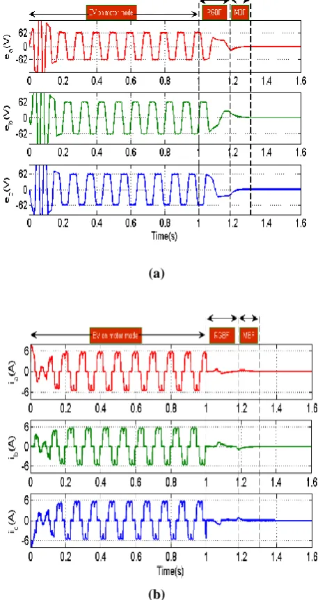
Similarly, waveforms of the BEMF’s and armature currents of the stator windings during motoring and braking state are shown in Figure 12 (a) and (b).Upon the braking procedure starts, the BEMF’s and stator currents of the generator start to decrease. When these three-phase BEMF’s and armature currents are too small, the controller switches to mechanical braking and it is relatively zero as shown in Figure 12.One can conclude that by adjusting the PWM duty-cycle in the VSC and SSIC, the dc-link voltage and state (charging/discharging) of battery can be controlled.
(a)
(b)
Figure 12 Waveforms of the ANN based proposed EV during motor and braking conditions (a) BEMF’s
( ) (b) stator current ( )
[image:8.595.42.293.454.572.2]International Journal of Innovative Technology and Exploring Engineering (IJITEE) ISSN: 2278-3075, Volume-8, Issue- 9S2, July 2019
Figure 13 Performance of battery in SSIC during motor and braking conditions
The drive-cycle speed curve is shown in Figure 14 (a). The EV is accelerated from standstill to a constant speed. Then, it is decelerated again to stationary condition. This procedure is repeated four more times at decreasing constant speeds. Hence, a realistic driving environment can be simulated, in which all the operating modes of the proposed EV can be activated. In Figure 14 (b), the motor-generator torque curve of the EV is depicted. During the EV acceleration, the required motor torque reaches about 10 N.m.
(a)
[image:9.595.306.538.290.724.2](b)
Figure 14 Simulated speed and torque curves of ANN based proposed EV regenerative braking system. (a) The simulated speed curve of 5-peak drive-cycle. (b)
Motor-Generator torque curve.
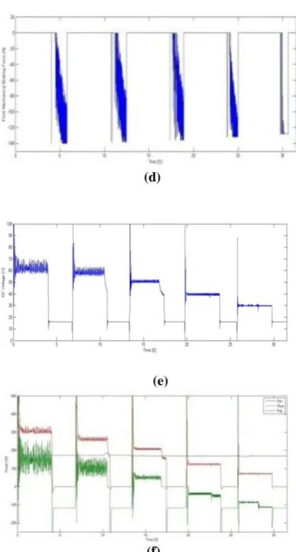
Figure 15 (a) and (b) shows the total braking force and rear breaking force which is generated accordance to the depression amount of force applied to pedal. Figure 15 (c) shows the regenerative braking region, in which the energy is fed back to the SSIC. At increased constant speeds, the regenerative braking torque is increased, which clearly
demonstrates the efficient operation of the proposed ANN controller. The DC link voltage varies accordingto the motor speed during EV acceleration and reduced to minimum during breaking whichachieve regenerative braking at low EV speed show in Figure 15 (e). However, it is difficult to achieve regenerative braking at further lowest EV speed due to relatively low voltage generated by the motor/generator. If the mechanical braking is not engaged under such circumstance, the EV will not stop in the specified distance. Hence, it is seen that the ANN controller reduces the regenerative braking torque as the EV speed decreases, ensuring reliable operation of the front mechanical braking system in Figure 15 (d).The PV power, Battery Power and DC bus power at both acceleration and breaking mode is shown in Figure 15 (f). It can be concluded that the braking force of the rear wheel is considerably smaller than the braking force of the front wheel. Moreover, the portion of the regenerative braking is increased at low speeds.
(a)
(b)
VEHICLES WITH SINGLE STAGE INTERACTION CONVERTER
(d)
(e)
[image:10.595.56.273.53.457.2](f)
Figure. 15. Simulated result of ANN based proposed EV regenerative braking system. (a)Total Braking Force. (b) Rear Braking Force. (c) Front regenerative Braking Force.
(d) Front Mechanical Braking Force. (e) DC Bus Voltage. (f) Power of PV/Battery/DC
VII. CONCLUSION
The main objective of this paper is developing a PV based charing EV system incorporated with BLDC motor as a driver. Since the amount of charing EVs are increasing rapidly, it is essential to go for renewable energy resoruces because of fuel demand. One of the other reason is CO2 emission. Due to the kinetic energy of EV, it needs to utlize both VSC and SSIC using a switching algorithm. Also it needs to distribute the braking force ANN is used to control it. BLDC controller with ANN is also compared with MPPT and PI controlled to verify the performance. From the experimental results the regeneration is increased 25% than the existing. Also 5 cycles is increased in the drive range of the EV. From the results and the performance comparison, it is concluded that the proposed ANN-BLDC for EV can provide better braking energy and it ensures Safe.