International Journal of Innovative Technology and Exploring Engineering (IJITEE) ISSN: 2278-3075, Volume-8 Issue-10, August 2019
Cascaded Rf-Fso-Vlc System using Df Relays
Rima Deka, Sanya Anees
Abstract - This paper presents performance analysis of cascaded radio frequency-free space optical communication-visible light communication (RF-FSO-VLC) system. The proposed model comprises of the RF link as the core network, a terrestrial optical link for providing last mile connectivity with the indoor cell users communicating through VLC environment. The RF link undergoes Nakagami-m distributed fading, while the terrestrial optical link is modeled by Double Generalized Gamma (DGG) distributed turbulence and Rayleigh-distributed misalignment losses. VLC links are characterized by the randomness in users’ position. Using statistical properties of system signal-to-noise ratio (SNR), outage and error performance of the proposed system is evaluated depending on whether the relays and the destination decode either perfectly or erroneously. The numerical results show that the system performance varies depending on field-of view (FOV) of the detector and user’s position. This is because as FOV increases along with the height of the LED, the outage probability of the system increases. Error probability depends on the type of detection techniques, where a heterodyne detection system performs better than a direct detection system. Moreover, through results it is inferred that severe fading and misalignment losses result in poor error performance of the considered system errors on the performance of the considered cooperative system. Index Terms- Decode-and-forward, free space optical communication, subcarrier intensity modulation, outage probability, visible light communication.
I. INTRODUCTION
Optical Wireless Communication (OWC) transmits information using signals from visible, infra-red, or ultraviolet spectrum. It has advantages such as it supports high speed communication, OWC transceivers are cost effective, use unlicensed band, and provide highly secure communication. The OWC is a promising communication technology which incorporates convenience of wireless and rate of optical communication. OWC systems can also be installed on those locations where wired communication is not feasible. The applications of OWC systems ranges from space-satellite links to terrestrial and underwater communication [1]–[3]. Where free space optical communication (FSO) is being considered for outdoor terrestrial communication, visible light communication (VLC) is being considered for indoor communication. Both are part of OWC but use optical signals of different frequency range, where FSO generally uses 850nm or 1500 nm, VLC uses 400-700 nm which is also employed in indoor LEDs [4], [5].
Revised Manuscript Received on August 10, 2019
* Correspondence Author
Rima Deka, Department of Electronics and Communication Engineering, Indian Institute of Information Technology Guwahati, Assam, India. Email: [email protected],
Sanya Anees, Department of Electronics and Communication Engineering, Indian Institute of Information Technology Guwahati, Assam, India. Email: [email protected]
Apart from contributing a large unlicensed bandwidth as compared to radio spectrum, the VLC technology is clustered with numerous other benefits like availability, no electromagnetic interference etc. FSO communication uses lasers and photo detectors to carry out transmission in the infra-red or UV frequency band. However sky conditions, scintillations, and misalignment losses limits the range and performance of FSO systems. Although at the time of initial installation, FSO transceivers are perfectly aligned, but natural disasters cause misalignment losses. Various solutions to reduce their impact are hybrid RF/FSO communication [7], radio-on-FSO [6], multiple-input-multiple-output (MIMO) based FSO systems, and relay based FSO systems. By applying different types of relay techniques, the coverage area of the FSO systems can be increased and this also improves capacity and error and outage probability of FSO systems. In [8], [9] cascaded RF/FSO communication systems are analyzed for decoding-and-forwarding (DF) and amplifying decoding-and-forwarding (AF) relays, respectively. Outage probability of asymmetric RF/FSO/RF stratospheric cooperative system has been presented in [10], where source/destination nodes and relays interact through radio channels and inter-relay communication is established using optical channel. FSO link undergoes Gamma-Gamma fading, radio links are Rician distributed. Recently, asymmetric RF/FSO/RF based cooperative systems using DF and AF are analyzed in [11], which can be implemented to communicate between already established/new radio networks using very fast speed. This paper discusses asymmetric RF-FSO-VLC
system in
Cascaded Rf-Fso-Vlc System using Df Relays
Fig. 1. System Model of DF based triple-hop RF-FSO-VLC system
II. SYSTEM MODEL
Communication through cascaded RF-FSO-VLC system using DF relays is depicted in Fig. 1. Relay R1 decodes electrical signal sent from source (S) re-encode it, then convert the electrical signal to optical signal further transmitting it via FSO link by using SIM scheme to R2. At R2, the photo detector at relay converts the received optical signal into its equivalent electrical form, re-encodes it to again optical signal and then transmits it through visible light environment to the end users. At the destination (D), again the photo detector present converts the optical signal in to the electrical signal through heterodyne or intensity modulation/direct detection (IM/DD) technique. In SIM, RF subcarriers are modulated based on the message signal, then with proper DC bias, the intensity of the optical source is altered. That is why optical signal can be modulated by any of the RF modulation schemes. The signal received at R1 can be expressed as
(1)
where, x is transmit signal from S, hs,r1RF channel gain, and
es,r1is AWGN N(0, 1 2 2
,
r r
).1 1 1
2
, , ,
s r hs r s r
is SNR of
RF link, where, denotes average SNR. Signal obtained
by R2 is given by
(2) where, ηr1,r2 represents photo electronic conversion ratio,
er1,r2 represents the complex valued AWGN, and Ir1,r2=Il It Ip
represents the atmospheric turbulence in R1-R2 links,
representing path loss, irradiance, and pointing errors, respectively [12]. Instantaneous SNR of the considered link, γr1,r2=I2r1,r2µr.
The average SNR, electrical SNR is defined as
µr1,r2 , r denotes the type of detection method, i.e., r =1
for heterodyne and r =2 for direct detection. The signal received at destination D is given by
(3) where, ρ is opto-electrical conversion ratio, is the
decoded signal at D, represents constant channel gain of VLC link connecting optical source to u-th user, represents transmit AWGN N(0, 2
,
r r
). Link SNR is givenby in which average electrical SNR is
defined as,
III. CHANNEL MODEL
RF, FSO, and VLC channel models used for the proposed system are discussed along with the various factors affecting
them.
A). RF Link: In this link, fading has Nakagami-m
distribution. Thus, link SNR will be having Gamma distribution with PDF [9]
(4) where, is a Gamma function and m is the fading parameter. CDF can be obtained as
(5)
where is lower incomplete Gamma function.
B). FSO Link: FSO link SNR has independent effects of
DGG irradiance and Rayleigh distributed misalignment losses. The unified PDF of the link SNR for both detection technique, is written as [12]
where,
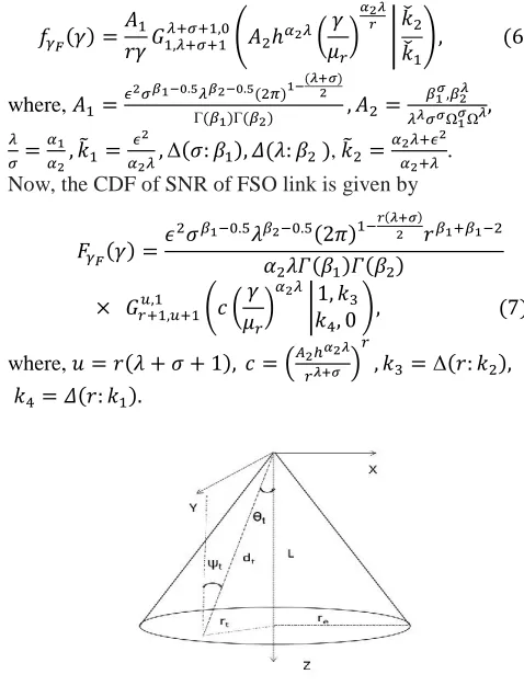
, . Now, the CDF of SNR of FSO link is given by
where,
[image:2.595.303.542.368.686.2]
International Journal of Innovative Technology and Exploring Engineering (IJITEE) ISSN: 2278-3075, Volume-8 Issue-10, August 2019
C). VLC Link: The VLC model is used for indoor cell
connectivity, where φc denotes photodiode’s (FOV), LED -
user distance is L, incidence angle, Ψt, irradiance angle,
θt, re denotes maximum radius a LED cell footprint as shown
in Fig. 2. The Euclidian distance for the user is given
by and cos(Ψ) = cos(φ) = L/ . PDF of
channel gain can be written as [13]
where,
, is the radius on the polar coordinate plane ,
A , is the photo detector area, is the gain of optical concentrator,
n denotes refractive index, is the order Lambertian emission defined as
with , denoting the transmitter semi-angle at half power. From PDF of channel gain, system SNR’s PDF, can be expressed by [13]
(9) where, ρ is responsivity of photo detector , γ ρ denotes transmit power, and is noise power
The CDF is given by
(10) Using Binomial approximation in (10), CDF is given by [13]
where, N denotes VLC points number, and
IV. STATISTICALPROPERTIESOFINSTANTANEOUSSNR
OFTHEPROPOSEDSYSTEM
A. CDF
For DF mixed based RF-FSO-VLC system, assuming that all relays are perfectly decoding the signal, the SNR is given
by,
(12)
where, and are instantaneous SNRs of RF, FSO, and VLC links, respectively. From (12), CDF can be expressed by
. (13)
By substituting (5), (7), and (11) in (13), closed-form expression for the CDF of instantaneous SNR of the considered system is obtained.
B. PDF
From (13), PDF of instantaneous SNR can be written as
By substituting the statistical characteristics of corresponding RF, FSO, and VLC links in (14), the final expression of PDF can be derived.
V. PERFORMANCE ANALYSIS
This section discusses performance of the DF based cascaded RF-FSO-VLC communication system is evaluated.
A. Outage Probability
Outage probability, , for the proposed system can be
expressed as
Using (13), the OP for the cascaded system is given by
. (16) Substituting (5), (7) and, (11) in (16) the OP can be expressed
as
. (17)
TABLE I
BER PARAMETERS FOR VARIOUS MODULATION TECHNIQUES [25]
Modulation Techniques u v
Coherent Binary Frequency Shift Keying (CBFSK) 0.5 0.5
Coherent Binary Phase Shift Keying (CBPSK) 0.5 1
Non-Coherent Binary Frequency Shift Keying (NBFSK) 1 0.5
Differential Binary Phase Shift Keying (DBPSK) 1 1
B. BER
For BER calculation, two scenarios are considered, (1) in which perfect decoding by relays and destination is assumed and (2) where, erroneous decoding by relay and destination also taken into consideration.
(8)
(14)
1) Perfect Decoding:BER computation formula used is as follow [14]
(18)
where, p and q are modulation techniques parameters as shownin Table I , denotes the average probability
of error ofthe system for perfect relaying. Substituting
from (13)in (18), the expression of BER of the
RF-FSO-VLC system isgiven by
. (19)
By substituting the values of , and, , the expression of BER is given by
(20)
where,
By simplifying, the BER can be derived as
+ + (21) where
d
d
d
d
d (22)
and is calculated as
. (23)
(24)
where,
By substituting (5), (11) in (22), and
using [15,Eqs.(8.4.3.1)], applying [16,
Eq.(07.34.21.0013.01)] , is given by
(25)
where,
. The integral of can be
derived by putting (5), (7) in (22), and using [15,Eqs.(8.4.3.1)], [16, Eq.(07.34.21.0013.01)] as
(26) The integral of can be expressed by putting (5), (7), (11) in (22), and using [15, Eqs. (8.4.3.1)], [16, Eq. (07.34.21.0013.01)] as
(27)
where,
and
Now, by substituting (23), (24), (25),
(26), and (27) in (20), the closed-form expression of BER for perfect decoding by nodes is obtained.
2)Erroneous Relaying: In DF based system, in case of binary modulation techniques, the received information is detected in each step, again encoding is done, further sent to other node. So, signal can be detected correctly or incorrectly at every step. So, the average BER of the system model must contain sum of all the possible scenarios in which the information can be decoded. It is given by
(28)
where, denotes the average probability of error of the system for errorneous relaying and and denote the error probabilities of RF, FSO, and VLC links, respectively. By using (18), the expression of BER for RF, FSO and VLC links are derived as follows.
a) BER of RF link: Substituting (5) in (18), BER can be
written as
International Journal of Innovative Technology and Exploring Engineering (IJITEE) ISSN: 2278-3075, Volume-8 Issue-10, August 2019
(30)
b) BER of FSO link: Substituting (7) in (18), error
probability of FSO link can be derived as
(31)
Fig. 3. Outage Probability of the DF based triple-hop
RF-FSO-VLC system
for different values of FOV of the photo detector and
height of LEDs
considering = 1.
Now by substituting [15, Eqs.(8.4.3.1)], applying [16, Eq.(07.34.21.0013.01)] in (31), BER is given by
(32) where, .
c)Error Probability of a VLC link:Substituting (11) in
(18), BER of a VLC hop can be written as
(33)
(34)
After substituting (30), (32), and (34) in (28), the closed-form
expression of BER for proposed system is obtained.
VI. NUMERICAL RESULTS
Numerical results for performance metrics derived in previous section are analyzed. The FSO link irradiance is assumed to be strong, i.e., (α1 = 1.8621, α2 = 1, β1 = 0.5
Fig. 4. BER of the triple-hop RF-FSO-VLC system for
both heterodyne(r =
1) and IM/DD (r = 2) for different values of .
Fig. 5. BER of the RF-FSO-VLC system for various
modulation scheme
under fixed fading environment.
, β2 = 1.8, Ω1 = 1.5074, Ω2 = 1). For the VLC link,
transmitter semi angle at half power θ1/2 is set at and
number of used LED
luminaries are considered to be 6 and m is taken as 5. The plots for OP of proposed system considering different height levels, different FOVs and strong irradiance scenarios is shown in Fig. 3. It is observed from the figure that the OP of the system decreases with the reduction in FOV of the photo detector as well as reduction in the height of the LED lights. It is because reduction in FOV, rises concentrator power for photo detector, thereby improving outage performance of considered cascaded system.
[image:5.595.321.550.113.305.2] [image:5.595.49.259.630.718.2]uthor-1 Photo Fig. 4 shows BER performance in case of erroneous
relaying for heterodyne detection and IM/DD considering different values of misalignment losses, L = 2.5 m, and FOV = . It is observed that heterodyne detection based systems perform better than direct detection based systems. It can also be seen that, for high misalignment losses, i.e., for lower value of the error performance of the system decreases. In Fig. 5, BER analysis of erroneous relaying for different modulation schemes, i.e., CBPSK, CBFSK, NBFSK, DBPSK are presented considering L = 2.5m, FOV = , fixed fading parameters for outdoor radio and optical links and fixed number of LEDs in case of the VLC link as described above. It is clearly observed that CBPSK performs best.
VII. CONCLUSIONS
The performance evaluation of the cascaded RF-FSO-VLC system is proposed for DF relays. Using statistical properties of system SNR, are used to derive the analytical expressions for the OP and bit error rate are obtained. The numerical results are obtained by varying parameters like misalignment losses under the strong irradiance conditions for both the detection types, heterodyne and IM/DD. It is seen that misalignment losses along with the different irradiance conditions affect the system performance and the indoor environment performance is dominated by the field of view of the detector and height at which LED luminaries are present.
REFERENCES
1. L. C. Andrews and R. L. Phillips, Laser Beam Propagation through
Random Media. Orlando, FL: SPIE PRESS, 2005.
2. Z. Ghassemlooy, W. Popoola, and S. Rajbhandar, Optical Wireless
Communications: System and Channel Modelling with MATLAB. Boca
Raton, USA: CRC Press, 2017
3. M. A. Khalighi and M. Uysal, “Survey on free space optical
communication: A communication theory perspective,” IEEE
Commun.SurveysTuts., vol. 16, no. 4, pp. 2231–2258, 2014.
4. Z. Ghassemlooy, L. N. Alves, S. Zvanovec, and M. A. Khalighi,
Visible
Light Communications: Theory and Applications. Boca Raton, USA: CRC Press, 2017.
5. T. Komine and M. Nakagawa, “Fundamental analysis for visible -
light communication system using LED lights,” IEEE Trans. Consum.
Electron, vol. 50, no. 1, pp. 100–107, 2004.
6. A. Bekkali, C. B. Naila, K. Kazaura, K. Wakamor, and M.
Matsumoto,
“Transmission analysis of OFDM-based wireless services over
turbulent radio-on-FSO links modeled by Gamma-Gamma
distribution,” IEEE Photon. J., vol. 2, no. 3, pp. 510–520,
2010.channels with pointing errors,” IEEE/OSA J. Opt. Commun.
Netw., vol. 5, no. 9, p. 11, Sept. 2013.
7. I. E. Lee, Z. Ghassemlooy, W. P. Ng, and A. Khalighi,
“Green-inspired
hybrid FSO/RF wireless backhauling and basic access signalling for
next generation metrozones,” 2012 2nd Int. Symp. On Env. Friendly
Energies & App., pp. 230–236, 2012.
8. S. Anees and M. R. Bhatnagar, “Performance of an
amplify-and-forward dual-hop asymmetric RF-FSO communication system,”
IEEE
J.Opt.Comm. Netw, vol. 7, no. 2, pp. 124–135, 2015.
9. ——, “Performance evaluation of decode-and-forward dual-hop
asymmetric radio frequency-free space optical communication
system,” IETOptoelectronics, vol. 9, no. 5, pp. 232–240, 2015.
10.E. T. Michailidis, N. Nomikos, P. Bithas, D. Vouyioukas, and A. G.
Kanatas, “Outage probability of triple-hop mixed RF/FSO/RF
stratospheric communication systems,” SPACOMM, pp. 1–7, 2018.
11.S. Anees and M. R. Bhatnagar, “Exact performance analysis of DF
based mixed triple-hop RF/FSO/RF communication system,” 2017
IEEE 28th PIMRC, pp. 1–5, 2018.
12.H. Alquwaiee, I. S. Ansari, and M. S. Alouini, “On the performance
of free-space optical communication systems over Double Generalized
Gamma channel,” IEEE Journal On Selected Areas In Com., vol. 33,
no. 9, pp. 1829–1830, 2015.
13.A. Gupta, N. Sharma, P. Garg, and M. S. Alouini, “Cascaded
FSO-VLC communication system,” IEEE Wireless Comm. Let., vol. 6, no.
6, pp. 810–813, 2017.
14.I. S. Ansari, S. A. Ahmadi, F. Yilmaz, M. Alouini, and
H. Yanikomeroglu, “A new formula for the BER of binary modulations with dual-branch selection over Generalized-K
composite fading channels,” IEEE Trans. Commun, vol. 59, no. 10,
pp. 2654–2658, 2011.
15.Prudnikov, B. A.P., M. Y.A., and O.I., Integrals and Series. New
York, USA: Gordon and Breach Science Publishers, 1990. 16.http://functions.wolfram.com/hypergeometricfunctions/meijerg.
AUTHORS PROFILE
Rima Deka received Bachelor in Technology (Electronics and Communication Engineering) from North Eastern Hill University, Meghalaya, India in 2013 and Masters in Technology from Assam Don Bosco University, India, in 2016. Currently, she is a research scholar in the Department of Electronics and Communication Engineering, Indian Institute of Information Technology Guwahati, Assam, India. Her research interests include optical wireless communications and cooperative communications. In her Post-Graduation, she has been awarded University Gold medal-2014 2016 for being University Topper in Electronics & Communication Engg. Branch.