by
Malcolm J. Grenness
B.D.Sc. (Melb) Dip. Prof. Mgt. (TCAE)
F.R.A.C.D.S.
Discipline of Anatomy and Physiology
School of Medicine
University of Tasmania
Submitted in fulfillment of the requirements for the Degree of Master of Medical Science
I hereby certify that this Thesis contains no material which has been accepted for a degree or diploma by the University or any other institution, except by way of background information and duly acknowledged in the Thesis, and to the best of my knowledge and belief no material previously published or written by another person except where due acknowledgement is made in the text of the Thesis.
Malcolm James Grenness
This Thesis may be made available for loan and limited copying in accordance with the Copyright Act 1968.
SUMMARY
The movement of the external ear canal, associated with jaw motion, relative to the concha region of the pinna has been studied. This issue is most relevant to the fitting and function of In-The-Ear hearing-aids. Pairs of open-jaw and closed-jaw silicone impressions were taken of 14 ears from 10 subjects. 3D coordinate data was obtained from the concha region and the anterior surface of the canal using a reflex microscope. The canal regions were plotted via an optical flat mirror. Proprietary area-based matching software was used to verify the stability of the concha region and evaluate distortion of the canal during jaw motion. The canal data from each pair was placed into the same coordinate system with their respective concha regions aligned using the area-matching software. Contour and difference maps of the canal data were used to demonstrate the amount of anterior-posterior (A-P), superior-inferior (S-I), and medial-lateral (M-L) movement that
occurred between the open and closed-jaw impressions. Rotations were also evaluated.
Analysis confirmed that the concha regions did not undergo significant deformation during jaw movement. The canal regions underwent varying amounts of internal deformation with the majority of canals conforming within an RMS of 400 pm across the entire surface. The majority of canals underwent significant morphologic change relative to the concha. Movement of the canal in the M-L plane ranged from 0 to 3.8 mm with a mean of 1.4 mm; 8 canals moved laterally, 5 canals moved medially and 2 ears did not move in the M-L plane. Movement in the S-I plane ranged from 0 to 3.7 mm with a mean of 1.3 mm; 9 canals moved inferiorly, 2 canals moved superiorly and 3 canals did not moved in the S-I plane. Movement in the A-P plane ranged between +3.5 mm and -3 mm, with 5 canals moving anteriorly, 3 ears moved posteriorly, and 4 ears moving in a mixed fashion.
The geometry of the external ear has created difficulties in acquiring accurate surface maps for analysis. The study has focused on the key areas of the pinna and canal previously reported to undergo significant change.
ACKNOWLEDGEMENTS
When my wife Susan presented me with clinical material that defied the conventional wisdom, I thought that a simple quantitative study lay ahead. I approached the School of Surveying at the University of
Tasmania and found that what I imagined to be a routine mapping exercise still lay in the realm of science fiction. I am indebted to Peter Zwart and Tony Sprent for their coutesy and encouragement.
I am especially indebted to Jon Osborn who has been the key link to directing me towards the different methodologies that resulted in a viable solution to the mapping problem.
There have been innumerable people who have (metaphorically) lent me their ears. It was following meeting William Douglas from
Minnesota in 1996 that I was reinvigorated after a period of slow progress. While discussing my problems one-day with John Parslow from CSIRO Marine Laboratories, he wrote out the mirror
transformation equations on a scrap of paper, without error.
My thanks to Richard Coleman for the use of Surfer 3-D graphics software; to Robert Anders for programming the Bursa-Wolf equations; to Andie Smithies at the Clinical Library for assistance through several frustrating literature searches, trying to find the key search words, before the advent of CD or on-line services; to Matthew Kirkcauldie for enhancing the colour photographs in the thesis; to Gordon Sanson at Monash University for his guidance on mapping and measuring small objects and for assistence with the use of the reflex microscope; and to Harvey Mitchell from Newcastle University for the generous use of DS Match proprietary software without which the project could not have proceeded.
My special thanks to my supervisor, Lee Weller, for clear insightful discussions that have spanned almost a decade. I am eternally grateful that I live mostly in the world of private clinical practice. However, I have been struck by the generosity of time and spirit that I have encountered throughout the myriad of Faculties in numerous institutions that I have had contact with during the course of this project.
I am especially indebted to my long-suffering wife Susan for the recruitment of subjects, the taking of impressions and indeterminate patience with my long years of study.
CONTENTS
Chapter 1 INTRODUCTION 1
1.1 An Observation 2
1.2 Terminology 2
1.3 Previous Investigations 3
1.4 Relevance of Ear Canal Movement 5
1.4.1 During audiometry 5
1.4.2 Affects on the sound attenuation of earplugs 5 1.4.3 Development of acoustical model of the ear canal 6 1.4.4 The fitting and performance of hearing aids 6 1.5 Anatomy of External Ear and Associated Structures 7
1.5.1 Pinna 7
1.5.2 The external auditory meatus 9
1.5.3 Movements 11
1.6 Hearing-Aid Use 13
1.6.1 Aim of hearing-aid fitting 13
1.6.2 Development of hearing-aids 13
1.6.3 Acoustic feedback 14
1.7 Earmould/Shell Manufacture 15
1.7.1 Impression technique 15
1.7.2 Impression materials 16
1.7.3 Impression modification 17
1.7.4 Earmould/hearing-aid shell manufacture 18
1.8 A Clinical Problem 19
1.9 Aim 20
Chapter 2 METHOD 21
2.1 Overview 22
2.2 Previous Investigations 24
2.3 Ear Measurement 26
2.3.1 Subjects 26
2.3.2 Sample size 26
2.3.4 Confidentiality 27
2.3.5 Ear impression 27
2.3.6 Measurement systems 28
2.3.7 Three-dimensional measuring instrument — Reflex
microscope 29
2.3.8 Accuracy and precision of Reflex microscope 29
2.4 Ear Impression Plotting 31
2.4.1 Design of the object mount 31
2.4.2 Alignment and securing of object 32 2.4.3 Collection of 3D coordinate data from impressions 33
2.5 Data Manipulation 34
2.5.1 Determination of mirror transformation 34 2.5.2 Alignment of coordinate data from concha fields 35 2.5.3 Application of transformation parameters to tragus field 37
2.6 Data Analysis 37
2.6.1 Movement within the concha 37
2.6.2 Movement within the tragus/canal 37 2.6.3 Movement of the tragus/canal relative to the concha 38
Chapter 3 RESULTS 40
3.1 Subjects 41
3.2 Accuracy and precision of data 41
3.2.1 Plotting of coordinate data from impressions 41 3.2.2 Mirror transformation of tragus/canal field into direct
coordinate system 42
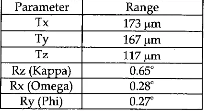
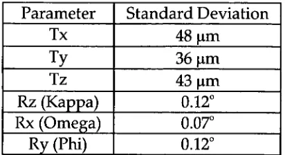
3.2.3 Parameters derived from area-matching concha fields 44
3.3 Movement within the Concha 47
3.4 Movement within the Tragus/canal 49
3.5 Movement of the Tragus relative to the Concha 53 3.5.1 Movement in frontal plane (x, y-axes) 53 3.5.2 Movement in the sagittal plane (z-axis) 55 3.5.3 Rotational movement of tragus/canal 57
Chapter 4 DISCUSSION 59
4.1 Impressions and Accuracy 60
4.1.1 Subjects 60
4.1.2 Practical considerations for accuracy 60
4.1.3 The regions mapped 61
4.2 Area-based matching 64
4.2.1 The concha field 64
4.2.2 Impression alignment 65
4.2.3 Multiple best-fit solutions of tragus/ canal field 68
4.3 Movement within the concha 69
4.4 Movement within the tragus/canal 70
4.4.1 Summary 70
4.4.2 Increased flexion at first bend 71
4.4.3 Future direction 73
4.5 Movement of tragus/canal relative to concha 73
4.5.1 Summary 73
4.5.2 Direction of movements 74
4.5.3 Quantum of movements 76
4.5.4 Symmetry 77
4.6 Two moments in time 78
4.7 Recent developments 78
4.7.1 CT Scanning 78
4.7.2 MR Imaging 79
4.7.3 Laser scanning 80
4.7.4 Area-matching and alignment 80
4.8 Future directions 81
Chapter 5 CONCLUSIONS 82
5.1 Method 83
5.1.1 Data collection 83
5.1.2 Alignment of impressions 83
5.2 Movement and distortion 84
5.2.2 Changes within the concha 84 5.3.3 Changes within the tragus/canal 84 5.3.4 Movement of tragus/canal relative to concha 84
5.3 Clinical implications 85
5.3.1 Hearing-aid fitting 85
5.3.2 Hearing-aid manufacture 86
5.4 Future directions 86
5.4.1 Mapping morphologic change in the external ear 86 5.4.2 Clinical evaluation of movement 87
5.5 Finale 87
References 88
Appendices 94
No 1 Mirror transformation equations 95
No 2 Concha field (spreadsheet): 96
Area-matching parameters and statistics
No 3 Tragus/canal field (spreadsheet): 101 Area-matching parameters and statistics
No 4 Concha field: 106
Area-matching residual data contour maps
No 5 Tragus/canal field: 109
Area-matching residual data contour maps
No 6 Tragus canal field: 112
Movement relative to concha field, frontal plane.
No 7 Tragus canal field: 115
Middle Ear Crus of
elix "i • ;
• • . ••. Tympanic Membrane
Antihelix ragus
Intertragic Notch
obe
Concha External Acoustic Meatus/
External Ear Canal Antitragus
Limit of ear canal length studied
Her N..
1.1 An Observation
Ear canal morphology changes upon smiling, talking and chewing (Morgan 1987). Casual observation suggests that there is wide variation in the types of movement possible between individuals. A standard reference, Cunningham's Textbook of Applied Anatomy 11 th ed., when discussing the external ear canal simply states "When the head of the mandible moves forward e.g. on opening the mouth, the cartilaginous part is widened".
Changes in ear canal morphology frequently impact upon the practice of audiology and the fitting of hearing-aids. It was observed that a patient's ear canal occluded upon opening the mouth (speech). This prevented the patient from speaking and hearing at the same time, inhibiting modulation of the voice. A subsequent hearing-aid fitting was inhibited by discomfort in the canal as a result of the canal portion of the hearing aid impinging on the soft tissues when the mouth was opened (Grenness 1990).
Cunningham's description does not seem adequate to explain this observation which provided the impetus to investigate movement in the ear canal related to jaw movements.
1.2 Terminology
The external ear consists of the auricle (pinna), attached to the side of the head, and the external acoustic meatus (ear canal) leading from it to the tympanic membrane and middle ear (Fig.1.1).
Hearing-aids are broadly classified according to their size and position in the external ear. These are:
Behind- The —Ear (BTE) In-The-Ear (ITE) In-The-Canal (ITC)
Completely-In-the—Ear (CIC)
The use and development of hearing-aids is outlined in section 1.6.
1.3 Previous_Investigations
Van Willigan (1976) while investigating craniomandibular disorder reported that ear canal volume increased on mandibular opening. It also appeared that, with a change in mandibular position, not only the ventral wall of the external ear but the entire meatus changed form.
A selection of anecdotal clinical observations illustrates the influence that neighbouring structures can have on ear canal morphology.
Hawke et al (1987) reported on a patient who had bilateral spontaneous temporomandibular joint herniation into the external auditory canal. The centre of each herniation was 30 mm medial to the lateral surface of the tragus. Heffez, Anderson and Mafee (1989) reported on two patients who were observed to have a bulge in the anterior wall of the ear canal caused by defect of the tympanic plate and a resultant intrusion of the mandibular condyle displacing retrodiscal tissues into the ear canal. The bulge converted to a depression upon wide mandibular opening.
Oliveira et al (1992) obtained silicon impressions of a subject at varying degrees of jaw opening. Transaxial diameters of the impression canals were measured with a digital caliper. Approximately a 25% change in this subject's ear canal with different jaw positions was observed in the antero-posterior (A-P) plane with essentially no change in the superior-inferior (S-I) plane. This was equivalent to an average increase, in the A-P direction, of about 0.7 mm in a typical adult over the length of the canal. He also reported upon a case with asymmetrical changes in which a 6% change occurred in the right ear, and a 21% change in the left ear.
Pirzanski (1996) reported on qualitative movement in ear canals relative to the concha region and described an "open-jaw" impression
technique. He reported that:
1. Mandibular movement affected 20% to 60% of subjects having impressions taken,
2. The cartilage in some subjects stretched up to 2mm, 3. The majority of changes in the ear canal occurred in the
anterior direction,
5. No changes or minimal changes were found in the posterior and superior part of the canal
He reported that the areas most susceptible to deformation were: 1. The ear aperture,
2. The middle canal section, and 3. The second turn of the canal.
These changes may occur separately or may all be present in one case.
Oliveira (1997) reported on MRI studies using an MRI enhancer fluid in the ear canal, measuring volumetric changes in the ear canal at varying degrees of mandibular opening and relating these changes to
underlying tissues. He concluded that the most significant changes that occurred in ear canal dimension with jaw motion were between the first and second turns of the canal.
This review of the literature has revealed an increasing awareness and reportage of problems associated with ear canal movement and its impact upon hearing-aid fitting and comfort.
This review also indicated that the major deformation of the canal occurred in the anterior wall. Very small changes occur in the S-I plane and in the posterior wall of the canal. There has been no information provided about movement within the concha region, although
Pirzanski (1996) used it as his means of aligning pairs of open-jaw and closed-jaw impressions.
The focus of Oliviera (1997) and Pirzanski (1996) most recent papers was the fitting of CIC hearing-aids. These hearing-aids lay entirely within the canal. Changes within the canal impact upon the fit and comfort of these aids irrespective of other changes that may be occurring.
However, ITE are still the most commonly fitted hearing-aids,
particularly amongst elderly patients. Their larger size leads to easier handling and manageability. These hearing-aids consist of a larger bowl that fills the concha region of the pinna and a smaller canal section that extends into the ear canal as fair as comfort and access allows. The concha part of the hearing-aid provides the major retentive element of the appliance. Forces applied to the canal section of the hearing-aid by adjacent anatomical structures are resisted by the greater bulk of the concha area. The hearing-aid as a whole must accommodate changes that occur in the canal. If the concha area is unyielding, the
accommodation of the movement must occur entirely within the canal.
There is a need to provide quantitative data on movements affecting the entire tissue-fitting surface of earmoulds and hearing-aids. In
particular, there is a need to provide quantitative data of morphological changes of the external ear canal relative to the concha region of the pinna associated with facial and mandibular movement.
1.4 Relevance of Ear Canal Movement
Knowledge of the nature and extent of changes in ear canal
morphology are relevant to a number of clinical and research situations.
1.4.1 During audiometry
Ventry, Chaildin and Boyle (1961) reported that pressure produced by audiometer earphones on the pinna might result in the collapse of the external ear canal. He commented that jaw movements tend to pull the cartilaginous external canal forward and downwards, causing an
increase in the patency of the canal.
Creston (1965) found that in ten cases of ear canal collapse during audiometry some patients appeared to have some narrowing of the orifice of the canal with a decrease in anterior posterior dimension. In other cases, the orifice of the canal seemed to be placed further
anteriorly under the tragus than normal; and in some cases it was noted that slight pressure on the anti helix caused the concha to ride under the tragus, thus compromising the meatus. There was no sex, age or race predeliction for collapse of the canal. The condition was more often unilateral and there was a possible familial tendency.
1.4.2 Affects on the sound attenuation of earplugs
Smith et al (1980) found that a difference of only 0.5 mm between ear canal dimension and earplug size exerted a dramatic effect on the sound pressure level in the ear canal.
1.4.3 Development of acoustical model of the ear canal
Zemplenyl, Gilman and Dirks (1985) measured ear canal length in order to correct for errors in sound pressure level (SPL) measurements taken in the ear canal due to the specific location of the microphone probe tip in the ear canal.
Stinson and Lawton (1989) measured entire ear canal geometry in cadavers in order to improve the prediction of sound-pressure level distribution within ear canals.
1.4.4 The fitting and performance of hearing-aids
Morphological changes can give rise to :
1. Impression inaccuracies during impression taking, 2. Acoustic feedback during movement,
3. Occlusion effect during movement, and 4. Discomfort during mandibular function.
Pirzanski (1996) highlighted problems with the manufacture and fitting of CIC hearing-aids as a result of ear canal movements. He noted that this type of hearing-aid was particularly vulnerable to acoustic
feedback related to jaw movements, and may slide completely out of the ear while the wearer was eating or speaking.
Skinner (1988) noted that venting an earmould helped to prevent the occlusion effect, that makes the bone-conducted sound of a person's own voice seem loud and hollow. Excessive venting can lead to feedback.
Movement may lead to changes in the amount of the air-gap between a hearing-aid and the adjacent skin surface. Therefore, movement in the ear canal associated with jaw movements can result in an alteration to the amount of acoustic seal or venting by an earmould leading to either in increase or decrease and acoustic feedback or the occlusion effect.
1.5 Anatomy of Ear and Associated Structures
Typically anatomical descriptions of the external ear divide it into the auricle (pinna) and external auditory meatus (ear canal) (Anson and Donaldson, 1967).
Developmentally, it would appear as though the auricle is derived from three tubercles, proliferation of mesoderm, at the dorsal end of the second (hyoid) pharyngeal arch. The tragus derives from three tubercles at the dorsal end of the first (mandibular) pharyngeal arch (Wood-Jones and I-Chuan, 1934).
Functionally it is more sensible to describe the external ear as consisting
of all the cartilaginous elements that make up the external ear and the outer portion of the external auditory meatus. The cartilage elements of the auricle and the tragus unite without any trace of their separate origins. Their separate origins could contribute to variable relations.
In the fitting of hearing-aids and the wearing of earplugs it is usual for
the earpiece to extend to the limits of the cartilaginous portion of the ear canal. Movement of the cartilaginous meatus relative to the bony
meatus during mandibular and facial movements may result in the earpiece causing mechanical irritation to the skin overlying the bone at the bone-cartilage joint. However this is not universally the case and many patients are able to tolerate earpieces that extend beyond this point. For many hearing-aid users this is desirable for reasons related the frequency response of the hearing-aid (Skinner, 1988).
For the purposes of this discussion only the salient anatomical features will be highlighted. It is movement of the antero-inferior aspect of the cartilaginous canal relative to the concha that is of most interest. Elements of the cartilaginous ear and associated structures that are likely to impact upon and lead to movement will be considered.
1.5.1 Pinna
Structure. The pinna is invested on both its medial and lateral aspects by integument that closely follows the irregularities of the underlying cartilage. Thus it is tightly bound to the perichondrium of the lateral surface by subcutaneous areola tissue, but much more
loosely attached on the medial surface. In the subcutaneous tissue there is little fat except in the lobule, which is entirely fat and tough fibrous tissue. Hairs are abundant but are for the most part rudimentary. Sebaceous glands are found on both surfaces; sudoriferous glands are few and scattered.
eminence on the concha to the mastoid part of the temporal bone. A superior ligament runs from the superior margin of the bony external auditory meatus to the spine of the helix. (Fig. 3 and 4)
Muscles. There are three extrinsic muscles. The anterior auricular muscle arises from the temporal fascia and inserts into the spine of the helix. The superior auricular muscle arises from the galea aponeurotica and the temporal fascia and inserts into the root of the ear; and
posterior auricular muscle arises from the mastoid process and inserts into the root of the ear. The extrinsic muscles are not normally used, but can be trained to move the external ear slightly; this power is greater in some people than in others.
Six intrinsic muscles can be distinguished. On the lateral surface there are four muscles: helicis major, helicis minor, tragus and antitragicus (Fig. 1.2). The pyramidal muscle of the auricle, which inserts into the spine of the helix, may be occasionally present.
M. helicis major
M helicis minor
M. antitragicus
4— Superior auricular ligament
.... —..Anterior auricular ligament
pyramidalis auriculae
M. tragicus
Fig. 1.2 Auricular Cartilage. Lateral view, Source: modified from Feneis (1976).
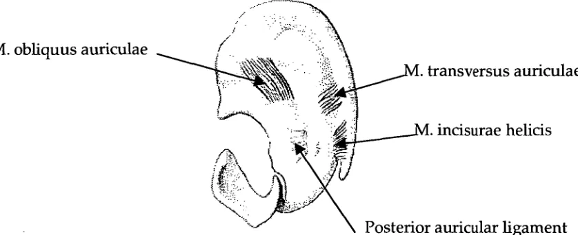
Medially there are two muscles: oblique muscle of auricle and the transverse muscle (Fig. 1.3). A muscle of incisure of helix may be occasionally present as caudal continuation of the transverse muscle.
transversus auriculae
incisurae helicis -
[image:17.562.72.491.78.249.2]Posterior auricular ligament M. obliquus auriculae
Fig. 1.3 Auricular Cartilage. Medial View, Source: modified from Feneis (1976).
As with extrinsic muscles, the intrinsic muscles are not normally used, but can be trained to move parts of the external ear slightly; this power is greater in some people than in others.
1.5.2 The external auditory meatus
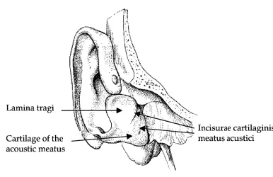
Incisurae cartilaginis meatus acustici Cartilage of the
[image:18.562.96.482.84.334.2]acoustic meatus Lamina tragi
Fig. 1.4 Auricular Cartilage. Anterior view, Source: modified from Feneis (1976).
The skin of the meatus covers the external surface of the tympanic membrane and is continuous with the skin of the auricle laterally. It is thick in the cartilaginous part where it carries fine hairs and sebaceous glands, the latter continuing along the postero-superior wall of the bony part. Numerous enlarged 'sweat' glands are found in the cartilaginous part. These secrete wax or cerumen and are known as ceruminous glands.
Relations. The anterior wall of the meatus is related to the
mandibular fossa medially and the parotid gland laterally. The inferior wall is closely bound to the parotid gland.
Condyle of mandible - Incisurae cartilaginis meatus acustici Part of parotid
gland
Tragu
Concha Tympanic membrane
Antihe •
[image:19.562.83.489.94.295.2]astoid air Helix
Fig. 1.5 Horizontal section through right ear canal, viewed from below, Source: Cunningham's Textbook of Anatomy (1972).
1.5.3 Movements of the external ear
It is assumed that for practical purposes the concha area does not deform during movements of the entire pinna and canal. This is based on published information reference texts, which show the absence of muscles within the concha area (Figs. 1.2 and 1.3). This assumption was tested during this study.
Reviewing Fig. 1.5 and simple observation suggests that as the condyle of the mandible moves forwards that portion of the tragus adjacent to the condyle may also move forward. At the same time the lateral
portion of the tragus may be pulled anteriorly, or medially and possibly posteriorly. Flexion of the cartilage of the anterior wall of the canal would be likely to occur principally at the notches in the cartilage of the ear canal. The bend that occurs in the ear canal at this point is clearly defined in ear impressions as the first bend. When subsequent ear impressions are taken with the mouth closed and open, i.e. the condyle fully seated in the glenoid fossa or positioned anteriorly on the articular eminence, the firs bend in the impression becomes more clearly defined (Grenness 1990).
mechanism for pressure equilibration. Their study did not support the concept of an elastic upper stratum to the tissues that has a recoil mechanism to control TMJ disc movement.
The study by Wilkinson and Crowley (1994) leads to the conclusion that it cannot be automatically assumed that as the condyle moves forward it must take an that is behind it, with it.
In subjects where the M. pyraidalis auriculae is present, it is possible that the tragus may be pulled superiorly relative to the concha (Fig. 1.2). Movements of the pinna as a whole must also be considered. Should the pinna as a whole be pulled anteriorly at a greater rate than the anterior wall of the canal, the result would be a narrowing of the canal.
Neame (1988) presented a clinical case in which a 12-year-old girl was able to occlude her external auditory meatus voluntarily by 'flipping' her tragus backward, where it stayed until she actively moved it forward.
Van Willigan (1976) showed changes in ear canal shape and position relative to the position of the maxilla. He found that opening jaw movement caused an increase in volume of the ear canal. However an increase in volume does not equate with an increase in size in all dimensions.
Examination of the diagrams in Van Willigan (1976) clearly show that there is an increase in size in the inferior-superior dimension. At best, it is difficult to evaluate whether there is an increase or decrease in the antero-posterior dimension. Many of the diagrams in this paper suggest that there was a decrease in this dimension upon jaw opening.
That a decrease in the A-P dimension is possible could go some way to explaining the case of ear canal occlusion reported in 1.1 above. If the anterior wall of the canal is generally moving forward then a reduction
in the A-P dimension can only be reasonably explained by a greater movement forward of the entire pinna, including the posterior wall of the canal. A study of movement of the canal relative to the pinna is therefore warranted.
1.6. Hearing-Aid Use
Hearing-aids consist of electronic circuitry with a microphone, receiver (speaker) and various volume and tone controls. These components may be contained in a housing that sits behind the ear and the sound is delivered to the ear canal via a tube that is held in the ear by an
earmould. Alternatively the components may be housed within the earmould in the case of ITE, ITC and CIC hearing-aids.
1.6.1 Aim of hearing-aid fitting
The goals of hearing-aid fitting are to make speech and other important sounds comfortably loud in the frequency regions between 250 and 6000 Hz and to limit the maximum acoustic output so that the sounds are not uncomfortably loud (Skinner 1988).
Five factors that help determine the utility of hearing-aids (in order) are:
1. Improves speech audibility,
2. Cosmetic and psychological acceptance, 3. Comfortable to the ear,
4. Good sound quality, and
5. Maximum speech discrimination.
The importance of the third factor, that a hearing-aid must be
comfortable or it won't be worn on a regular basis, almost goes without saying. "Anyone who has tried wearing a hearing aid with an ill-fitting ear-mould, for example, knows from personal experience that it almost can't be done" (Killion 1982).
1.6.2 Development of hearing-aids (Katz 1985)
Prior to 1955, body aids were essentially the only available wearable type of hearing-aid. These are usually worn under clothing on the chest with an earpiece passing to the ear. The distance between the
microphone (at the chest) and the receiver output (at the ear) of the body aid reduced the possibility of acoustic feedback at higher output levels. Body aids came with a range of stock earpieces, the one of best fit being chosen. An effective acoustic seal was not required due to the large distance between the microphone and the receiver output.
and laboratory techniques for the fabrication of these earmoulds were derived directly from dentistry.
The availability of very small, efficient electret microphones,
correspondingly small receivers and further battery miniaturization has facilitated packaging the entire hearing-aid within the concha and ear canal: In-The-Ear (ITE) hearing-aids. The further development of
circuits in which the input is phase-shifted such that the output is out of phase with the input has enabled greater amplification with less
feedback. Most ITE aids are of the 'custom' type with the components built into a shell made from an impression of the user's ear. 'Modular' ITE aids are built into a case of fixed shape that fits into a matching depression in the custom ear-mould (Katz 1985).
More recently Completely-In-the-Canal (CIC) hearing aids have been developed to be inserted deeper into the ear canal with a handle to facilitate their removal. This type of hearing aids has proved to be particularly vulnerable to acoustic feedback related to jaw movements. In addition, when the wearer is speaking or eating, the CIC may continuously slide out of the ear (Pirzanslci 1996).
Despite improvements in the electronic technology the fit and comfort of hearing-aids is still vital to successful fitting.
1.6.3 Acoustic feedback
Acoustic feedback either positive or negative occurs when amplified sound escapes via the ear-mould or the ear canal and arrives back at the hearing-aid microphone. When the escaping sound, after processing by the hearing-aid produces a level in the ear canal equal to or greater than the level generated by the leaking sound, oscillation can occur if the phase conditions are right. The result may be variously identified as whistling, squealing, buzzing, humming or howling.
There are three major possible effects of acoustic feedback: 1. Oscillation can occur, making the hearing aid useless,
2. The frequency response of the aid can be greatly altered, even if oscillation is not occurring, and
3. Major alterations in response e.g. the creation of sharp peaks as oscillation is approached. These sharp peaks result in poor transient characteristics or "ringing" when sounds are processed by the hearing-aid (Lybarger 1982).
The miniaturization of hearing-aids has also brought the microphone closer to the source of sound leakage. This, together with the advent of higher-powered hearing aids has resulted in acoustic feedback
becoming a greater problem. Higher sound pressure levels increase the sound leakage from the receiver back to the external environment to be re-amplified by the hearing-aid circuit. Macrae (1988) reports that 10%
of the clients to whom the National Acoustic Laboratories (Australia) provides aids require high-powered hearing aids (2 cc coupler gains of 65 dB or greater).
Skinner (1988) lists ten means by which feedback can be prevented within certain unspecified limits.
1 Reducing size of or eliminating vents. 2. Damping resonant peaks.
3. Reducing the high frequency response. 4. Notch filters (Macrae 1982).
5. Using thick walled tubing.
6. Using soft instead of hard material for the ear-mould (or using a soft material with a hard body in the ear-mould). 7. Using dental liner material around the ear canal and concha
surfaces of a Lucite ear-mould (pp270). 8. Increasing the length of the canal.
9. Improving the fit of the ear-mould, particularly in the region of the tragus.
10.Using the three-stage impression technique developed by Fifield.
Items 6 to 10 relate to different prosthetic aspects of the ear-mould, i.e. mould material, geometry (length and fit) and impression technique.
1.7 Hearing-aid Manufacture
Hearing-aid manufacture starts with the taking of an impression of the external concha region of the pinna and the ear canal as far medially as is required for the design of the aid. The impression is processed into a hollow shell for an ITE or CIC hearing-aid or an earmould of varying design for a BTE hearing-aid.
1.7.1 Impression technique
Typically a foam or cotton block attached to cotton thread is placed just beyond the point in the ear canal to be recorded by the impression. Impression material, either silicone based or ethyl methacrylate is syringed into the ear being careful to avoid voids in the material, not to distort the ear and to record the detail of the tissue surface (Juneau 1983, Morgan 1987).
There is differing opinion on the subject of mandibular position and movement during impression taking.
impression is obtained if it is built up in stages, using a suitable packing tool. No recommendation regarding mandibular position was made.
Babbington (1975) recommended that when taking ear impressions for hearing-aids, due to shape changes in the meatus during jaw
movements, the patient should be placed in a comfortable sitting position and asked to relax. The teeth should not be clenched nor should the mouth be completely slack.
Sullivan (1975) states that "it is proper to make a precise, accurate fit rather than a tight, expanded one.... An impression taken with no consideration of the occlusion (of the ear orifice) and the ability of the ear to stretch can not give you true measurements to be used in the construction of an earmould".
Fifield, Earnshaw and Smither (1980) in describing the multi-stage impression technique made no recommendation concerning jaw
movement or position during impression taking. They did recommend jaw movement while testing the effectiveness of the seal under
pressure.
Morgan (1987) recommended that jaw movements be encouraged during taking of impressions. He stated that when impressions were made with natural movements occurring, the impression noted these changes. He provided no evidence for this statement. It would appear that the final shape of the impression would be achieved when the impression material had set to a sufficient extent to render further movement uncomfortable. Pirzanski (1996) commented that this view was still widely recommended in impression-taking manuals.
Anecdotal evidence also suggests that this is a very commonly held clinical opinion.
Macrae (1989) reported that the chance of sealing the ear with ear-moulds made with the multistage impression technique was 88%. Ear-moulds that were lubricated and ear impressions that were 'patted down' produced hearing-aids with more feedback (more transmission loss).
Pirzanski (1996) stated that patients should be advised to open their mouth at least 2/3 of the way. Stabilizing the jaw with a mouth prop prevents accidental closure.
1.7.2 Impression materials
Ear impressions may be taken with a variety of impression materials of varying viscosities. Many of these are unsatisfactory for making ear-moulds for high-powered hearing-aids because of inadequate elastic properties and poor dimensional stability.
Lear and Earnshaw (1987) pointed out that most impression materials designed for the hearing-aid industry have a non-reacting oil added to the base paste. This allows the material to be mixed in the hands and provides good separation of the set impression from the relatively dry skin lining the ear canal. This also results in poor accuracy and poor dimensional stability. Lear and Earnshaw recommended dental addition-cured silicone elastomeric impression materials were dimensional stability and accuracy were required. (e.g. Reprosil, Dentsply/Caulk, USA).
Morgan (1987) also advocated the use of silicone impression materials over ethyl methacrylate, both, which seemed to be in wide use.
Despite the apparent importance of the impression material's physical properties Pirzanski (1996) concluded that the technique of impression taking might have a greater impact than the material used for
fabricating earmoulds.
1.7.3 Impression modification
It is routine practice to apply a coating of wax or other polymer to the impression prior to processing. The purpose of the spacer is to:
1. Ensure that the finished ear-mould fits snuggly into the ear in order to prevent acoustic feedback,
2. Compensate for polymerization shrinkage of the mould during curing,
3. Eliminate surface defects and irregularities,
4. Provide a smooth tissue-fitting surface for hygiene and aesthetics, and
5. Compensate for surface material loss during polishing.
General wax build-up: A general wax build-up is applied to the entire surface of the impression by dipping the impression into a wax bath. The distribution and thickness of the wax varies depending on the temperature of the molten wax, the thermal capacity of the impression material, the length of time that the impression is left in the wax and the number of times that the impression is dipped (Bootiffoyd 1965).
Volatile acrylic cements may also been applied by dipping or with a fine brush to impressions to achieve a thinner coating of more uniform thickness (Pither 1988).
and location of this special wax build-up can best be defined as an art. There are no formal guidelines as to how this should be applied.
Technicians learn the art through experience. The amount of build-up may be varied according to the amplification of the hearing-aid.
Macrae (1989) supported applying special wax build-up to impressions in a review of ear impression and ear-mould technology. He reported that applying special wax build-up eliminated feedback in all but 6% of adults who use high-powered post-auricular hearing aids.
1.7.4 Earmould/ Shell manufacture
Earmoulds may be made directly in the ear using self-curing acrylics or silicones. They are more commonly made indirectly by making a replica of the ear from an impression. The earmould is then made into the replica.
Many articles have addressed the subject of ear anatomy, ear impression materials and technique and mould manufacture (e.g. Sullivan 1975, Juneau 1983, Fifield, Earnshaw and Smither 1980).
Earmoulds are made from either rigid or flexible materials. Impressions are invested with a variety of materials e.g. dental duplicating media (agar agar) or gypsum products. When the
impression is removed from the investment a negative mould space is left into which is packed the ear-mould material, which is then cured or processed. The cured mould is removed from the investment and
finished with the placement of a tubing hole, ventilation hole if required, shaping of the mould as is required by the case and the finishing and polishing of the tissue fitting surface. Hearing-aids have electronic components inserted after the shell has been fabricated. Highly polishing the tissue fitting surface results in some loss of material and alteration in the fit of the earmould.
1.8 A Clinical Problem
Macrae (1989) recommended further study into the distribution of the build-up that occurs to multi-stage impressions to give guidelines for the application of special wax build-ups. Taking a further step back, there appears to be limited information available on the morphological changes that can occur in human ear canals or the potential for
displacement of tissue.
Furthermore this practice appears to be successful in reducing feedback, however it is fraught with danger as is illustrated by the following case (Grenness 1990):
A long-term hearing-aid user attended an Audiologist complaining of feedback. It was confirmed that the feedback was caused by sound leakage past an ill-fitting earmould. An impression was taken and a new mould ordered from the manufacturer. Upon fitting, the hearing-aid still feedback excessively. A further impression was taken. The laboratory took additional care in applying a special wax build-up to the tragus region of the ear impression, and processed the mould. This was successful in alleviating the feedback problem. The patient
returned twelve months later again complaining of feedback. A new mould was ordered and the problem eliminated. A further six months later the patient returned with feedback and a new mould was made. The cycle was then repeated three months later, then every four to five weeks. Finally an earmould could not be made that did not feedback. In addition the patient was now experiencing temporo-mandibular joint pain dysfunction syndrome. It was not determined how long this occurred for and a thorough examination was not undertaken to reveal the extent of the problem. However it was a significant problem to the patient.
The practice of applying positive pressure to the tissue bearing areas of an ear canal is not without consequence. It has been shown that the ear canals of hearing-aid users are of a larger cross-sectional area than non-users (Kokot-Schimdt 1979). This is readily evident to any practicing clinician. It could be expected that displacement of tissue for long periods will induce permanent changes, either atrophy or hypertrophy. In the case of ear canals, atrophy of dermal, subcutaneous, cartilage and/or bone tissue elements results in an enlargement of the ear canal.
Current methodologies may not be adequate in all cases. This case was ultimately resolved (at least to date) by taking a medium-viscosity silicone impression of the ear canal with the patient's mouth open (open-jaw impression). No wax build-up either general or special was applied to the impression prior to processing. Why this should be the case is not immediately obvious. Other similar cases have been assisted with patients adopting a variety of postures, e.g. with head between the knees.
1.9 Aim
The purpose of this investigation was to study:
1. Movement of the tragus/canal region of the ear canal relative to the concha area in order to demonstrate the range and direction of movement and determine whether the narrowing of the canal does occur.
2. Movement within the concha region of the ear in order to demonstrate whether this region undergoes deformation. 3. Movement within the tragus/canal region of the ear in order to
demonstrate the range of deformation. - 4. Precision/ Accuracy of the measuring system
2.1 Overview
Pairs of open-jaw and closed-jaw ear impressions were taken of
patients. Subject selection was not intended to be representative of any group or the population as a whole. Practical issues relating to
collecting data and developing a successful method of analysis limited the sample size. The sample size was intended to be large enough to draw conclusions about the range and extent of movement. It was not expected that conclusions could be drawn about specific groups of subjects.
The concha and the anterior surface of the tragus/canal regions of the impressions were mapped separately using a Reflex microscope.
The resultant 3D coordinate data was manipulated:
1. Transposition of coordinates plotted via a mirror using Cartesian Geometry (Parslow, 1994) so that concha and tragus/canal fields were in their correct spatial relationship and in the same coordinate system.
2. Alignment of the concha region of impression pairs using proprietary area-matching software, DS Match, utilizing a least-squares solution (H. Mitchell, version 23, 1995). 3. Application of transformation parameters from
area-matching using seven parameter similarity transformation equations (Harvey 1995) to tragus/canal regions
This resulted in the tragus/canal fields from impression pairs being in the same coordinate system with their respective concha fields
coincident.
The manipulated data was analyzed:
1. The area-matching software applied to the paired concha fields was used to evaluate distortion within the concha region that may have occurred as a result of opening the mouth.
2. The area-matching software was applied to the paired tragus/canal fields to evaluate distortion within the tragus region that may have occurred as a result of opening the mouth.
3. Analysis and Visualisation software, Surfer (Golden Software, version 6.04, 1997) was applied to the paired
tragus/canal fields to evaluate movement in the trag-us/canal region relative to the concha as a result of opening the mouth.
Statistical analysis was performed on data collected to determine the accuracy and precision of the recording system and error in the manipulated data.
3D Coordinate data
Concha A Concha B
Metal Die
•
Movements:
M-L, S-I Distortion/ Matching
of Concha Flow Chart:
DS Match Parameters
3D Coordinate data Mirror
Trans-formation
Parameters Tragus A Tragus B
•
Mirror transformed data Tragus Am Tragus Bm Tragi in correct
orientation to concha
Tragi in correct orientation and concha aligned
•
Trag-us Am Tragus Bmp
•
Overlay Maps
(Surfer) Difference Maps DS Match Parameters (Surfer) (Tragus /canal)
•
Movements:
2.2 Previous Investigations
Ear canal geometry has been measured using a variety of means.
Boothroyd (1965) measured moulds at two convenient places with a micrometer screw gauge and the results compared with the
corresponding dimensions of the ear. Sufficient data was not published to determine the accuracy of the method.
Van Willigan (1976) compared sections of ear impressions that were sectioned at depth of 6, 8, 10, and 12 mm from the ear opening. Sections were compared with each other by photographing them and projecting the negatives on top of each other. No measurements were taken but the changes in morphology were represented visually.
Smith et al (1980) used ear canal calibrators in 8 different sizes ranging from 5 through to 12 mm in diameter to measure the major and minor axes on the canal. Each of the calibrators was measured with precision calipers prior to the investigation and found to be accurate in size.
McHugh and Purnish (1984) used a caliper to measure the diameter of cylinders of set impression material to the nearest 0.1 mm.
Zemplenyl, Gilman and Dirks (1985) used an operating microscope (Zeiss OPMI, with 250 mm focal length objective lens whose depth of focus was less than 1 mm) to focus on the umbo of the eardrum. The microscope was then refocused on a point at the end of an earpiece in the ear canal. The difference between the two points was determined by measuring the distance that the microscope head traveled along its track. This distance was measured with calipers. In no individual did the repeated ear canal measurement differ by more than +/- 1mm.
Kamel, Kunov and Abel (1986) reproduced standard ear impressions in polymethyl-methacrylate. The reproduced mould was encased in a mixture of polyester resin, hardener and talcum powder; the
encasement included notches to act as fiducials and to facilitate the alignment of the sections later during digitization. The mould was sectioned, destroying 1mm thickness of the mould with each slice. The sections were photographed and a computer system was used to digitize the serial sections.
Lear and Earnshaw (1987) tested various impression materials
according to International Standard ISO 4832 (1984). Elastic recovery after compression was measured using a dial gauge comparator to an accuracy of 0.01 mm. Dimensional accuracy and dimensional stability of impressions of a steel block bearing engraved markings were
measured using a travelling microscope (toolmakers microscope) with an accuracy of +/- 1 mm.
Macrae (1988) measured impressions and earmoulds using a Sylvac digital caliper with reported resolution of 0.01 mm, accuracy was 0.03 mm and repeatability of measurements of 0.01 mm. All
measurements were carried out under binocular x2 magnification. Each measurement was repeated three times and the mean of the three values was taken as the estimate of the true value. Five dimensions of each object were measured:
Major axis (long axis) at the meatal entrance, Minor axis (Short axis) at the meatal entrance, Meatal length,
Major axis at the meatal tip, and Minor axis at the meatal tip.
In order to assess the repeatability of measurements carried out with the digital caliper each of the five dimensions of a single impression was measured 100 times. The average standard deviation from the mean values was 0.1032 mm.
Stinson and Lawton (1989) obtained rubber moulds with a setting time of 20 minutes from human cadavers. Each earmould was orientated with the canal pointing vertically on a turntable. A probe was mounted horizontally on a three-axis movement micrometer. X, y and z data from the probe was combined with angle data from the turntable to produce x, y, z, coordinate data. Approx. 100 points were collected over the surface along the canal. Accuracy was reported at about 0.03 mm. This study was conducted for the purpose of measuring ear canal volume.
Abel et al (1990) measured impressions using calipers to measure the maximum and minimum diameters at the concho-meatal angle and the cartilaginous-bony angle. "Because there were no fiducial points on the canals from which measurements could be taken, there was no
guarantee that the measurements of these diameters could be faithfully reproduced". Accuracy on repeated measurement was 1 mm.
Oliveira et al (1992) used silicone ear impressions and a digital caliper on one subject to measure the effect of jaw position and magnetic resonance imaging to define the three-dimensional structure of the canal and visualize key underlying tissues.
EgoIf at al (1993) used a computer assisted tomographic (CT) scanner in two steps to make radiographic images of parasagittal cross sections at uniform levels along the length of the canal. Accuracy was evaluated by comparing areas of cross sections appearing in radiographic images of a cadaver ear canal to cross sectional areas of the corresponding
mould of the same canal. This equates to accuracy in the order of +/- 1 mm.
Pirzanski (1996) demonstrated changes in canal morphology by placing a closed-jaw impression into the bisected open-jaw impression reverse. Hollow spaces were seen between the closed-jaw impression and the bisected investments prepared from the open-jaw impressions. The method demonstrated gross qualitative change. No quantitative measurements were recorded.
Malard et al (1997) found that CT scan measurements in the lateral portion of the external ear canal were not reliable, quantitative usefulness being limited to the bony meatus.
Oliveira (1997) reported on volumetric changes in the ear canal, using MRI upon an ear canal filled with an MRI enhancer fluid to enable imaging of the of the canal space itself.
None of these methods provide reliable quantitative data on ear canal movement relative to the concha region of the pinna.
2.3 Ear Measurement
In order to quantify changes in morphology of the surface in the external (third) ear canal relative to the concha area during functional movements of associated structures it was necessary to map the surface features of the canal and concha region in three dimensions (3D).
2.3.1 Subjects
Ear impressions were taken of patients attending the Tasmanian Centre for Hearing, Hobart, for new or replacement hearing-aids, and staff. Subjects were selected on an ad hoc basis to provide:
1. Male and female subjects, 2. A wide age range,
3. Known hearing-aid fitting difficulty, 4. Existing hearing-aid users, and 5. Non hearing-aid users.
Subject selection was not intended to be representative of any group or the population as a whole.
2.3.2 Sample size
Practical issues relating to collecting data and developing a successful method of analysis limited the sample size. The sample size was intended to be large enough to draw conclusions about the range and extent of movement. It was not expected that conclusion could be drawn about specific groups of subjects.
2.3.3 Ethics approval and consent
Ethics approval was sought and approved by the University Ethics Committee (Human Experimentation), University of Tasmania.
A consent form was drafted outlining the aim of the project, the subject's involvement and material risks, and included a no disadvantage clause.
2.3.4 Confidentiality
Once taken, impressions were numbered. A secure register was maintained to record relevant patient details and impression
identifying numbers. Impressions were stored in hard plastic containers with only their identifying number in the lid. The identifying number was used as the reference for all subsequent analysis stages.
2.3.5 Ear impression
The starting point for 3D reconstruction of the canal was an impression of the ear canal and concha in an elastomeric (dental) impression material. This relates to the clinical situation where earmoulds/shells for hearing aids are fabricated starting with an impression of the ear (concha and external third of canal down to the bone-cartilage joint). The material used for this investigation was a medium viscosity
condensation silicone dental impression material (Xantopren H (green), Heraeus/Kulzer, Germany). This material has been in use at the
Tasmanian Centre for Hearing for many years. It gives good surface detail without being so fine that it is likely to cause significant trauma to the lining epidermis upon removal. The manufacturer reports recovery from deformation equal to or greater than 98.0 % and linear dimensional change of equal to or less than —0.90 %.
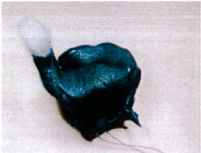
Open and closed-jaw impressions of the same ear were taken
[image:36.562.177.375.138.289.2]immediately after each other. Thus a pair of impressions was obtained from each ear.
Fig. 2.1 Ear impression, cotton block in place
2.3.6 Measurement systems
The ear canal is relatively inaccessible to measuring instruments. In practice it is not practical to measure an ear canal directly. One must rely on an indirect method. A number of systems reported from past investigations were considered for this task. They can be separated into:
1.Contact, 2.Non-contact
A replica of an ear canal may be more able to tolerate a mechanical contact system, but is also not suitable for measurement due to its inaccessibility. Thus either a direct impression of the ear using an elastomeric material must be used or a replica of that impression fabricated from a more rigid material. A rigid replica was required for mechanical measuring systems to prevent distortion of the direct impression during measurement. However the additional
manufacturing stages involved in producing an impression replica result in distortion of the replica when compared to the original impression.
2.3.7 Three-dimensional measuring instrument — Reflex microscope
The Standard Reflex microscope is a non-contacting instrument enabling direct measurement in 3D of small objects (up to 110 mm) which can lead to 3D computer representations. The observer views the object through an ordinary stereoscopic microscope. A small light spot appears in the field of view, and it can be guided to coincide with desired points on the surface. The x, y and z coordinates are monitored by Moire fringe encoders, and the counting interface passes the position on request to a computer through an RS232 link.
The object is carried on a conventional two-dimensional (x, y-axis) slide. The slide was first translated to give the observer a view of the point to be measured. This is done either by a track ball or computer program. The microscope, mirror and measuring spot are carried on a vertical (z-axis) slide, and the observer translates the microscope using
stereoscopic vision to judge the height coincidence of the light spot with the object point. The vertical slide was moved via a finger slide.
Multiple views of an object can be recorded and combined where there are common points to each view.
The microscope magnification is selectable as x 5, x 10, and x 20.
Accuracy and precision of measurements is dependent upon the visual acuity of the operator. The measuring mark may have a diameter of 20 um, 10 um, and 5 um. A full description and explanation of the reflex principle, the Reflex microscope, and examples of its application may be found in a paper by Scott (1981).
The Reflex microscope has also been used to: measure the dimensions of the glenoid fossa (Owen, Wilding and Adams 1992), measure areas of dental caries in teeth (Neilson and Pitt, 1993), measure the cement thickness of porcelain crowns (Shearer, Gough and Setchell 1996), measured tooth morphology and wear in two small animals (Bezels and Sanson, 1997), measure tooth movement on sequential casts during orthodontic treatment (Battle and Ryan, 1998), and measure palatal clefts defects (Owman-Moll, Katsaros and Friede 1998).
2.3.8 Accuracy and precision of the Reflex microscope
Accuracy and precision is limited by the design of the instrument, but is also dependent on the operator.
Accuracy is a measure of the closeness of an observation to its true
observations are free of systematic errors (or that any systematic errors will not influence the results or conclusions).
Speculand, Butcher and Stephens (1988) reported on the accuracy and precision of the reflex microscope. They found a mean
under-measurement of 0.28%, i.e. 0.14 mm per 50 mm. They found no
systematic error between the three microscope lenses. They also found that increased magnification does not necessarily confer greater
accuracy. The explanation for this was concerned with point identification being a matter of 'decision' and not 'vision'. It is
necessary to choose the degree of magnification most appropriate to the size of the object.
The microscope was calibrated according to the manufacturer's
instruction. All measurements were taken using x20 magnification and the 20 jim measuring spot.
Analysis of coordinate data (section 2.6) involved the subtraction of paired datasets to produce difference data. Systematic error affecting one dataset would affect its pair in the same way. Thus any small systematic errors are likely to cancel rather than accumulate.
Precision is a measure of the repeatability of the measurements. It is indicated by the standard deviation of the recorded values from their mean value. Evaluation of precision was an important function when performing analysis and drawing conclusions from datasets that which involved several measurements and which had undergone several mathematical manipulations.
All impressions were plotted as ordered-grids (section 2.4.3) and the precision of recordings was determined by the instrument. Precision in the x and y-axes was determined by the precision of the Moire fringe encoders, reported by the manufacturer as 1 iAM.
Precision of z-axis values
The precision of the reflex system (including operator error) z-axis values was tested by scanning the same profile (30 points) 14 times on a single ear impression. Points were collected using a ordered-grid
routine. The data was placed into a spreadsheet consisting of 14
columns, each column representing a profile. The mean value for each point was calculated. The standard deviation from the mean of the 30 coordinates was then calculated. The mean of the standard deviations was calculated. This was taken as the average precision of the z-axis measurements.
2.4 Ear Impression Plotting
The areas to be plotted, the anterior surface of the tragus/canal and the concha, were at near right angles. They could not be viewed directly from the same direction, as the microscope required. A fixed mirror was required to optically transpose the tragus/canal into the same plane as the concha. Determination of the parameters of that
transposition allowed the placement of the tragus/canal into the correct spatial relationship with its corresponding concha.
2.4.1Design of object mount
[image:39.562.122.460.370.604.2]The object mount consisted of a brass mounting plate 120mm x 120mm with a platform 25 mm x 25 mm raised 10 mm above the base. The platform had two deep grooves and locating holes engraved into its surface. The ear impression was seated on the raised platform with the concha region approximately horizontal and the tragus/canal region pointing vertically. Adjacent to the platform was a 50 mm diameter optical flat mirror, lambda 4, set at approx. 45 degrees to the platform (Fig. 2.2).
Fig. 2.2 Object mount with impression and mirror in place.
Plotting coordinates via the mirror increased the optical distance from the microscope to the object. The surface plotted through the mirror
appeared to be below the base of the microscope stage, beyond the recording range of the instrument. As a result the specimen mount was raised by approximately the distance from the object to the mirror (4 cm). The object mount and 4 cm block were fastened securely to the
When viewed through the microscope, the concha region could be seen directly. The anterior surface of the tragus/canal could be seen through the mirror. The two areas were moved into the viewing range of the microscope by the x, y slide (Fig. 2.3).
2.4.2 Alignment and securing of object
A system of aligning and securing the impressions to the mount was required to allow for the alignment of the concha of both impressions from each impression pair into approximately the same position.
Subsequent area-based matching of the concha fields was more reliable when the fields to be matched with already in close alignment.
1. Trimming the impression: The lateral surface of each impression was cut to a plane with a scalpel. Deep locating notches were then cut into this plane.
2. First impression base: The object platform, described above, had a dollop of polyether (Permadyne, Espe, Germany) elastomeric impression material (coloured purple or pink) placed onto it. While the material was still workable, one impression from each pair was seated into the polyether with the canal part of the impression pointing vertically. A
minimum thickness of 2mm of polyether was maintained. Thus an impression base consisted of a surface with large ridges to fit into the base of the impression, and a surface with two small ridges and plugs to fit onto the platform. 3. Register: The polyether impression base was trimmed flush
with the edges of the brass platform. The platform, polyether and impression were boxed with dental modeling wax. Bite registration material (Automix Bite Registration material, 3M, USA) was injected into the wax box, around the ear
impression to create a register. The tragus region of the impression was not covered. The wax box was carefully loosened. The register and impression were removed. The other impression from the impression pair was fitted to the register and together with the wax box re-fitted around the platform.
4. Second impression base: Different coloured polyether (either pink or purple) was injected into the space between the impression and the platform and allowed to set. Each impression pair consisted of two impressions with two differently coloured bases, allowing for remounting of impressions.
6. Identification: Impression pairs were placed into separate boxes with identifying numbers.
The horizontal plane correlated to the mid-sagittal plane of the human body. The x-axis was close to the A-P direction. The y-axis was close to
the S-I direction. The z-axis was close to the medio-lateral (M-P) direction
2.4.3 Collection of 3D coordinate data from impressions
The microscope had a number of recording routines that could be used to aid in the collection and recording of data of which two were used: free-format and ordered-grid.
Free-format. The measuring mark was moved to any desired point using the track ball to move the x, y stage, and the finger wheel to move the measuring mark onto the surface of the object (z coordinate). A foot switch was pressed to record the x, y, z coordinates of the mark, as monitored by the moire fringe encoders. Accuracy and precision of each x, y, and z value was dependent upon the operator.
Ordered-grid, with parallel profiles in y direction. Parameters were set for x and y-axis intervals. The measuring mark was moved to the southern, left-hand point of the field. Activation of the foot switch moved the mark to the next predetermined x, y location. The finger wheel was used to adjust the z position of the mark. The foot switch was pressed, the coordinates of the mark were recorded and the step motors moved the stage to the next point. Accuracy and precision of the x and y values was determined by the instrument, and the z value was dependent upon the operator.
The ordered-grid routine recorded the first coordinate of each routine as 0,0,0. The x and y-axis values were changed as the x, y slide moved to the next predetermined point. In order to place multiple fields from the same object into the same coordinate system it was necessary to record the x, y, z coordinates of the mark, as displayed on the monitor, which coincided with 0,0,0.
Coordinate data was collected from two fields on each impression: 1. The anterior surface the tragus/canal was plotted via the
mirror, and
2. The concha region was plotted directly.
Each field was plotted using a separate free-format routine. Several separate measurement files were used to collect data points on some fields. Coordinate data was recorded as ASCII files of x, y and z
Southern border
Concha fields ranged between 9 to 12 mm in the x-axis (Antero - posterior) and 20 to 30 mm in the y-axis (superior — inferior).
[image:42.560.154.487.152.418.2]Tragusicanal fields ranged between 9 to 20 mm in the x-axis (medial — lateral) and 10 to 19 mm in the y-axis (superior — inferior).
Fig. 2.3 Object mount, viewed from above, showing concha field (right) and tragus/canal field (left).
2.5 Data Manipulation
2.5.1 Determination of mirror transformation
In order to transform coordinate data recorded as a mirror image into a direct image it was necessary to derive transformation parameters from
common points that could be viewed directly and through the mirror.
No such common points existed on ear impressions due to their morphology.
equations based on Cartesian geometry to derive unit vectors and a constant (Parslow 1994).
The final equation followed the general form:
Xr = X — (b) (xi) where X was the direct coordinate Xr was the mirror image coordinate
b was a constant derived from the coordinates xi was the unit vector.
A full explanation and the equations appears in Appendix 1.
The unit vectors and constant were used to calculate coordinates in the direct plane from the tragus/canal coordinates plotted via the mirror. This resulted in the tragus/canal fields being in the correct spatial relationship with their respective conchae.
2.5.2 Alignment of coordinate data from concha fields
To achieve the aim of measuring movement in the ear canal relative to the concha region it was necessary to precisely align the surface plots of the concha fields of each impression pair. Care was taken in the
alignment of the impressions during the mounting procedure. However the precision of the alignment can be further enhanced by using
computer software to match the coordinate data from the fields to be matched. Two methods were explored:
Feature-based matching: This involves the detection of distinct features in an image, the description of these features in mathematical terms and a decision as to whether two descriptions refer to the same element in the data being matched. In image matching, feature-based methods are usually faster, more reliable (less susceptible to gross error i.e.
mismatches), and is likely to find a match with poor a priori orientation values (Fryer, McIntosh and Oh, 1998).
In this case skin pores were readily identifiable on individual
impressions. Attempts to identify common pores on impression pairs failed. Attempts to mark suspected common points were unsuccessful.
Area-based matching: This involves finding the orientation of best correlation between corresponding fields in images that are being matched. In image matching, this method is usually more precise than feature-based matching (Fryer, McIntosh. and Oh 1998), but may not be as reliable as feature-based matching because it is more likely to match areas that do not correspond. (This is discussed below).