SUPERVISOR DECLARATION
„I hereby declared that I have read through this dissertation and I found that it has comply the partial fulfilment for awarding the degree of
Bachelor of Mechanical Engineering (Thermal Fluid)‟
Signature : ………
Supervisor : Mr. Mohd Afzanizam B. Mohd Rosli
A STUDY OF FLOW PATTERN IN AUTOCLAVE USING COMPUTATIONAL FLUID DYNAMICS (CFD)
MUHAMMAD HILMI BIN HASSIM
This dissertation is submitted as partial fulfilment of the requirement for the degree of Bachelor of Mechanical Engineering (Thermal Fluid)
Faculty of Mechanical Engineering University Teknikal Malaysia Melaka
STUDENT DECLARATION
“I hereby declare that this dissertation entitle “A Study of Flow Pattern In Autoclave Using Computational Fluid Dynamics (CFD)” is my own work and result except for
the work that had clearly stated the sources.”
Signature : ………
Student : Muhammad Hilmi b. Hassim
ACKNOWLEDGEMENTS
ABSTRAK
ABSTRACT
NO. LIST OF TABLE PAGE
1. Table 1. Comparison of Pressurize Gases 4
2. Table 2. Thermal conductivity k values
for various materials at 300K 16
3. Table 3. Typical value of h. 18
4. Table 4. Reynolds value and flow type 21
5. Table 5. Models Menu setting 35
6. Table 6. Models Menu setting 48
NO. LIST OF FIGURE PAGE
1. Figure 1. Industrial Horizontal Autoclave 3
2. Figure 2. Schematic of Autoclave 4
3. Figure 3. Flow diagram of the autoclave-based manufacturing
process 5
4. Figure 4. Typical Cure Cycle Diagram 6
5. Figure 5. Prepreg Schematic 7
6. Figure 6. Type of Composite material 9
7. Figure 7. Fibre Orientation 9
8. Figure 8. Schematic diagram of heat transfer mechanisms
through a typical mould and lay-out. 14
9. Figure 9. Conduction heat transfer 16
10. Figure 10. Temperature and velocity distributions near a surface 17
11. Figure 11. Radiation Component 20
12. Figure 12. CAD process flow 26
13. Figure 13. Project Flow Chart 27
14. Figure 14. Literature Autoclave Dimension 28
15. Figure 15. Body of Autoclave 29
16. Figure 16. Autoclave floor 30
17. Figure 17. Autoclave door 30
18. Figure 18. Autoclave inlet 31
19. Figure 19. Fan Installation 31
20. Figure 20. 3D Model in Gambit 32
21. Figure 21. Completed Mesh 32
22. Figure 22. Boundary Input 33
23. Figure 23. Boundary Placement 33
24. Figure 24. Continuum Types 34
25. Figure 25. Solver Setting menu 34
[image:8.595.121.523.133.778.2]27. Figure 27. Velocity Inlet Boundary Condition 36
28. Figure 28. Solution Controls menu 36
29. Figure 29. Solution Initialization menu 37
30. Figure 30. Residual Monitors menu 37
31. Figure 31. Iterate menu 38
32. Figure 32. Velocity Contour 38
33. Figure 33. Literature CFD Result 39
34. Figure 34. Velocity Vector 40
35. Figure 35. Literature CFD Result 40
36. Figure 36. Pathline View 41
37. Figure 37. Body of Autoclave 42
38. Figure 38. Autoclave floor 43
39. Figure 39. Autoclave door 43
40. Figure 40. Rectangular Cut Extrude 44
41. Figure 41. Full half autoclave drawing with dimension 44
42. Figure 42. 3D Model in Gambit 45
43. Figure 43. Completed Mesh 45
44. Figure 44. Boundary Input 46
45. Figure 43. Boundary Placement 46
46. Figure 46 Continuum Types 47
47. Figure 47. Solver Setting menu 47
48. Figure 48. Operating Conditions menu 48
49. Figure 49. Velocity Inlet Boundary Condition 49
50. Figure 50. Solution Controls menu 49
51. Figure 51. Solution Initialization menu 50
52. Figure 52. Residual Monitors menu 50
53. Figure 53. Iterate menu 51
54. Figure 54. Empty Autoclave Velocity Contour Result 52 55. Figure 55. Empty Autoclave Velocity Vector Result 53
56. Figure 56. Empty Autoclave Pathline Result 54
57. Figure 57. Velocity Contour (Side View) 55
58. Figure 58. Velocity Contour (Mould View) 56
59. Figure 59. Velocity Vectors (Side View) 56
[image:9.595.114.524.70.781.2]LIST OF SYMBOL
SYMBOL DEFINITION
Degree
T Temperature
t Time
r Reaction rate
C Heat capacity
w Resin mass fraction
H Resin heat of reaction
Thermal diffusivity
Q Heat flux
k Thermal conductivity of solid
A Area of solid
x Distance
' Region of thickness
Tw Temperature Wall
T∞ Temperature Fluid
h Convective heat transfer coefficient
c Speed of light
Product of wavelength
f Frequency
Emissivity of the surface
Stefan-Boltzmanns constant
Density of fluid
V Mean velocity of fluid
L Characteristic linear dimension
Re Reynold number
Nu Nusselt number
Kf Thermal conductivity of the fluid
Pr Prantle number
Cp Specific heat
Bi Biot number
LIST OF ABBREVIATION
ABBREVIATION DEFINITION
ASME American Society of Mechanical Engineers
BMI Bismaleimide
CAD Computer Aided Design
CAM Computer Aided Manufacturing
CFD Computational Fluid Dynamics
CMC Ceramix Matrix Composites
FEM Finite Element Method
FRP Fibre Reinforced Polymers
MMC Metal Matrix Composites
NC Numerical Control
PMC Polymer Matrix Composites
2D 2 Dimensional
ACKNOWLEDGEMENT i
ABSTRACT ii
LIST OF TABLE iv
LIST OF FIGURE v
LIST OF SYMBOL viii
LIST OF ABBREVIATION x
1 INTRODUCTION
1.1 PROJECT OBJECTIVE 2
1.2 PROBLEM STATEMENT 2
1.3 PROJECT SCOPE 2
2 LITERATURE REVIEW
2.1 INTRODUCTION TO AUTOCLAVE 3
2.1.1 Structure of Autoclave 4
2.1.2 Operation Principle 6
2.2 INTRODUCTION OF COMPOSITE 8
2.2.1 Fibre Orientations 9
2.2.2 Fibre Properties 10
2.2.3 Matrix Properties 10
2.3 HEAT TRANSFER MECHANISMS 12
2.3.1 Heat transfer through mould and lay-up 13 2.3.2 Composite Heat Transfer Model 15
2.3.6 Reynold Number 21
2.3.7 Nusselt Number 22
2.3.8 Prantel Number 23
2.3.9 Biot Number 24
3 METHODOLOGY
3.1 COMPUTER AIDED DESIGN INTRODUCTION 25
3.2 COMPUTER-AIDED DESIGN 26
3.3 COMPARISON WITH LITERATURE REVIEW 28
3.4 COMPUTATIONAL FLUID DYNAMICS 28
3.5 MODEL CREATION 29
3.5.1 MESHING 32
3.5.2 FLUENT 34
3.6 CFD RESULT 38
3.6.1 Velocity Contour 38
3.6.2 Velocity Vector 39
3.6.3 Pathline 41
3.7 3-DIMENSIONAL MODEL CREATION 42
3.7.1 3-D CFD MODEL 45
3.7.1.1 GAMBIT 45
3.7.1.2 FLUENT 47
4 RESULT AND ANALYSIS
4.1 CFD RESULT (Empty Autoclave) 52
4.1.1 Velocity Contour 52
4.1.2 Velocity Vector 53
4.1.3 Pathline 54
4.2 CFD RESULT (With Mould) 55
4.2.1 Velocity Contour 55
5 DISCUSSION
5.1 RESULT COMPARISON 59
6 CONCLUSION AND RECOMMENDATION
6.1 CONCLUSION 61
CHAPTER 1
INTRODUCTION
1.0 INTRODUCTION
To investigate the flow pattern of air in autoclave using CFD without mould.
To investigate the flow pattern of air in autoclave using CFD with mould.
To develop a simulation of air circulation using CFD with mould.
1.2 PROBLEM STATEMENT
The visualization of air flow pattern in Autoclave resulted from simulation of CFD software to allows the user to fully optimize the usage of autoclave by the means of simulations.
1.3 PROJECT SCOPE
Flow simulation in steady state condition without part(mould) on point A. Flow simulation in steady state condition with part(mould) on point A. Flow simulation in Horizontal Autoclave.
CHAPTER 2
LITERATURE REVIEW
2.1 INTRODUCTION TO AUTOCLAVE
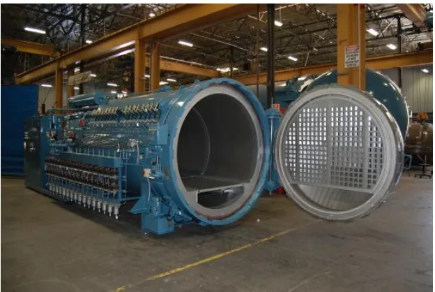
[image:19.595.164.476.503.712.2]Autoclave is classified as modification of Pressure Vessel. Pressure vessel has to comply to strict regulation such as American Society of Mechanical Engineers (ASME). Donald define autoclave as an airtight steel vessel used to heat substances and objects under very high pressures. An autoclave have many size and construction. The operation principle for many type of autoclave are nearly the same. Autoclave are used in many area such composite manufacturing and sterilization of medical equipment.
Figure 1. shown the Horizontal Autoclave for Industrial purposed. The operating pressure can range from 275 kPa to 67000 kPa and temperature range of 1200 C to 7600 C ( Taricco - 2007). An autoclave allow a chemical reaction to occur at higher temperature and pressure depending on the material type and purposes. The pressurize gases used in autoclave are air, nitrogen and carbon dioxide. The comparison of gases shown in Table 1.
Table 1. Comparison of Pressurize Gases
Air Nitrogen Carbon dioxide
Advantage Cost Cheap No Pollution
Low combustibility
No Pollution Cost Intermediate
Disadvantage High combustibility Cost Expensive
Hazardous to Human High Density
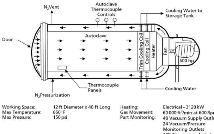
[image:20.595.119.493.457.692.2]2.1.1 Structure Of Autoclave
Figure 2. shown the typical schematic of an autoclave. An autoclave are equipped with an heating element, insulation element, autoclave cart, vacuum pump, circulation fan, temperature with cure connection and a sealed door. Heating element can be compose of electric heater, indirect gas firing based heater or steam heater. Heating element release heat into autoclave during cure processes. Insulation element is used to prevent too much heat loss and its end result reduce the heating cost during cure process. Insulation are also used to prevent the autoclave from exceeding maximum operating temperature. Circulation fan is used to provide mass flow for temperature uniform and heat transfer to mould. This accomplished with a blower mounted at rear of autoclave. The airspeed varies from application but normally in range of 1 m/s to 10 m/s.
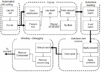
Autoclave operate principle are nearly the same as pressure cooker. The mould are place on top of autoclave trolley. In order to cure the part, pressure and temperature are applied to the laminate in a predetermined cure cycle (Figure. 4). The temperature cycle is necessary to trigger the resin polymerization reaction. After the autoclave door are secured, the air inside bag is removed by vacuum pump. The chamber are then pressurize until reached cure pressure. The heater are turn on slowly on the beginning of cure process and increased pressure. Dwell allows the temperatures to equilibrate in the moulding and can be used to control the time at which gelation occurs. Note that initially the resin viscosity drops as the laminate heats up. Hold serves to extend the time that the resin remains at low viscosity, allowing consolidation and elimination of porosity. This pressure and temperature are hold until 90 minutes where second pressurize process occur. The higher pressure increased the temperature as well. The second stage will occur around 2 hour or more. The cooling process are done slowly to allow heat escape the chamber and reduce the risk of danger to operator. The mould are removed after cure process is completed.
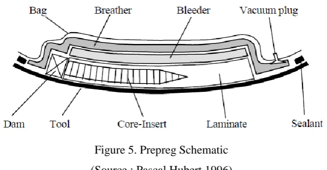
The convectional cure cycle is composed of two stages; first stage for consolidation and second stage for full cure. The base material used in autoclave processing is a pre-impregnated sheet, commonly called prepreg. This prepreg contains fibres pre-impregnated with a catalyzed thermoset resin which will cure at high temperatures.
Figure 5. Prepreg Schematic (Source : Pascal Hubert,1996)
Composite in its most basic form is composed of at least two elements working together to produce material properties that are different to the properties of those elements on their own. In practice, most composites consist of a bulk material (the matrix), and a reinforcement of some kind, added primarily to increase the strength and stiffness of the matrix. This reinforcement is usually in fibre form.
Three main groups:
Polymer Matrix Composites (PMCs) :
Also known as FRP - Fibre Reinforced Polymers (or Plastics) These materials use a polymer-based resin as the matrix, and a variety of fibres such as glass, carbon and aramid as the reinforcement. This type are the most common.
Metal Matrix Composites (MMCs) :
Increasingly found in the automotive industry, these materials use a metal such as aluminium as the matrix, and reinforce it with fibres such as silicon carbide.
Ceramic Matrix Composites (CMCs) :