UNIVERSITI TEKNIKAL MALAYSIA MELAKA
TRAFFIC LIGHT WITH WARNING VOICE
This report submitted in accordance with requirement of the Universiti Teknikal Malaysia Melaka (UTeM) for the Bachelor’s Degree in Electronics Engineering
Technology (Telecommunications) (Hons.)
by
MUHAMAD AZRIFF BIN ZULKAPLI B071110021
900719-14-5037
UNIVERSITI TEKNIKAL MALAYSIA MELAKA
BORANG PENGESAHAN STATUS LAPORAN PROJEK SARJANA MUDA
TAJUK: Traffic Light with Warning Voice
SESI PENGAJIAN: 2014/15 Semester 2
Saya MUHAMAD AZRIFF BIN ZULKAPLI
mengaku membenarkan Laporan PSM ini disimpan di Perpustakaan Universiti Teknikal Malaysia Melaka (UTeM) dengan syarat-syarat kegunaan seperti berikut: 1. Laporan PSM adalah hak milik Universiti Teknikal Malaysia Melaka dan penulis. 2. Perpustakaan Universiti Teknikal Malaysia Melaka dibenarkan membuat salinan
untuk tujuan pengajian sahaja dengan izin penulis.
3. Perpustakaan dibenarkan membuat salinan laporan PSM ini sebagai bahan pertukaran antara institusi pengajian tinggi.
4. **Sila tandakan ( )
SULIT
TERHAD
TIDAK TERHAD
(Mengandungi maklumat yang berdarjah keselamatan atau kepentingan Malaysia sebagaimana yang termaktub dalam AKTA RAHSIA RASMI 1972)
(Mengandungi maklumat TERHAD yang telah ditentukan oleh organisasi/badan di mana penyelidikan dijalankan)
Alamat Tetap:
SA4-1-A, LORONG PANDAN PERTAMA 5, PANDAN UTAMA, 68000 AMPANG, SELANGOR
Disahkan oleh:
Cop Rasmi:
DECLARATION
I hereby, declared this report entitled “Traffic Light with Warning Voice” is the results of my own research except as cited in references.
Signature : ……….
Author’s Name : ………
Date : ………
MUHAMAD AZRIFF BIN ZULKAPLI 14 JANUARY 2015
APPROVAL
This report is submitted to the Faculty of Engineering Technology of UTeM as a partial fulfillment of the requirements for the degree of Bachelor of Engineering Technology (Bachelor Degree in Electronics Engineering Technology (Telecommunications) (Hons.). The member of the supervisory is as follow:
……… (Win Adiyansyah Indra)
ABSTRAK
Projek ini adalah berkaitan dengan sistem lampu isyarat dengan amaran suara. Sistem ini menggunakan aplikasi lampu isyarat biasa tetapi dinaik taraf dengan menambah satu sistem untuk memberi amaran kepada pejalan kaki apabila kenderaan bergerak ke arah lintasan pejalan kaki. Objektif projek ini adalah untuk mengurangkan perlanggaran antara kenderaan dan pejalan kaki. Ia juga untuk memberi amaran kepada sikap pemandu tentang kepentingan peraturan lalu lintas kepada masyarakat dan juga termasuk keselamatan pejalan kaki dengan memberitahu pejalan kaki bahawa kenderaan bergerak menuju ke arah pejalan kaki . Kajian projek ini adalah sangat penting kerana untuk mengurangkan kadar kemalangan di antara kenderaan dan pejalan kaki. Ia juga memberitahu bahawa kepentingan keselamatan pejalan kaki kepada pengguna jalan raya. Dengan laporan ini, ia boleh memberikan maklumat yang lebih lanjut mengenai projek ini. Akhir sekali, dengan harapan yang tinggi bahawa projek ini boleh digunakan untuk kajian yang akan datang dan adalah penting kepada masyarakat.
ABSTRACT
This project is related to the traffic light system with voice alert. This system uses ordinary light application but upgraded by adding a sound system to give warning to pedestrians when the vehicle moving towards the pedestrian crossing. It is also to alert the driver’s attitude about the importance of traffic rules to communities and also includes the safeness of pedestrians by notifying incoming vehicles towards the pedestrian. The study of this project is very important because to reduce the accident rate between vehicles and pedestrians. It is also notes that the importance of pedestrian safety for road users. With this report, it can provide the more information about the project. Lastly, with high hopes that this project can be applied to a future study and it is important to the community.
DEDICATION
Special dedication to
My beloved parents, family, supervisor, friends and personal who have encouraged, guide and inspired me throughout journey of education.
Thank you for all support.
ACKNOWLEDGEMENT
In the name of Allah the Most Gracious and the Most Merciful.
First and foremost, I would like to express my deepest gratitude to Mr. Win Adiyansyah Indra, my project supervisor for giving the continuous advices, supports and necessary information needed to accomplish this project. His immense knowledge and guidance helped me in all the time of project and writing of this thesis.
Last but not least, I would like to thank to all my friends and everybody that involved in the progress of this project for the stimulating discussions, for the sleepless night we were working together before deadlines, and for all the supports that were give.
I humbly thank you.
TABLE OF CONTENT
Abstrak v
Abstract vi
Dedication vii
Acknowledgement viii
Table of Content ix
List of Tables xi
List of Figures xii
List Abbreviations, Symbols and Nomenclatures xiii
CHAPTER 1: INTRODUCTION 1
1.1 Background 1
1.2 Problem Statement 2
1.3 Project Objectives 3 1.4 Project Scope 3 1.5 Conclusion 4
CHAPTER 2: LITERATURE REVIEW 5
2.1 Introduction 5
2.2 Traffic Light 5
2.2.1 History 6
2.2.2 The origin of colour scheme for Traffic Lights 8
2.3 Pedestrian Crossings 11
2.3.1 Types of Pedestrian Crossings 12
2.3.1.1 Pelican Crossings 12
2.3.1.2 Puffin Crossings 12
2.3.1.3 Zebra Crossings 13
2.3.1.4 Toucan Crossings 13
2.3.1.5 Pegasus Crossings (Equestrian Crossings) 13
2.4 Infrared Detector 14
CHAPTER 3: METHODOLOGY 16
3.1 Introduction 16
3.2 Process Development 16 3.3 Components 17
3.3.1 Software Component 19
3.3.1.1 Arduino 19 3.3.2 Hardware Components 20 3.3.2.1 Arduino Uno 20
3.3.2.2 BC547 Transistor 21 3.3.2.3 Resistor 22 3.3.2.4 Capacitor 22 3.3.2.5 LED (Light Emitting Diode) 23
3.3.2.6 Infrared LED Sensor 24
3.3.2.7 Photo Diode Sensor 25
3.3.2.8 Buzzer 25 3.3.2.9 PCB Board 26 3.3.2.10 Jumper Wire 27 3.3.2.11 AC/DC Adapter 27
3.4 Method of data collection 28
CHAPTER 4: RESULT & DISCUSSION 29
4.1 Introduction 29
4.2 The components Setup at PCB Board & Arduino Uno 29
4.3 Results Based on Hardware 31
4.4 Project Flow 34
CHAPTER 5: CONCLUSION & FUTURE WORK 35 5.1 Introduction 35
5.2 Conclusion 35 5.3 Future Work 36
REFERENCES 37
APPENDICES 39
LIST OF TABLES
3.1 List of components used 18
LIST OF FIGURES
2.1 The installation of a traffic signal in San Diego in December 1940 8
2.2 Modern Railroad Semaphore 9
2.3 Pedestrian crossing in Malaysia 11
2.4 Emission of energy by vehicle and road surface 15
3.1 Flow chart 17
3.2 A screenshot of the Arduino IDE 19
3.3 Arduino Uno 20
3.4 BC547 NPN Transistor 21
3.5 Resistor 22
3.6 Capacitor 22
3.7 LED 23
3.8 Infrared LED Sensor 24
3.9 Photo Diode Sensor 25
3.10 Buzzer 25
3.11 PCB Board 26
3.12 Jumper Wire 27
3.13 AC/DC Power Adapter 27
4.1 The Green LED light up when power supply connect to Arduino Uno 30 4.2 Schematic diagram for connection of component on PCB board with
Arduino Uno 31
4.3 The Green LED of traffic light and red LED of pedestrian light lighted up 32
4.4 LED changes when presence of vehicle 32
4.5 The buzzer will alert the pedestrian when presence of vehicle 33
LIST OF ABBREVIATIONS, SYMBOLS AND
NOMENCLATURE
AC - Alternating Current AREF - Analog Reference DC - Direct Current
ICSP - In Circuit Serial Programming
IDE - Integrated Development Environment
IR - Infrared
LED - Light Emitting Diode PCB - Printed Circuit Board PWM - Pulse-Width Modulation USB - Universal Serial Bus
1.1 Background
Nowadays, vehicles in Malaysia have rapidly increasing, particularly in large urban areas such as Kuala Lumpur, Johor Bahru, Penang and others. Therefore, there must be a need to arise for a simulating and upgrading system for the traffic controllers for a better accommodation regulating on the increasing demand by road users around the world. Traffic lights are commonly used device to regulate roadway intersection traffic and pedestrians crossing with a view to both safety and smoothness of vehicle flow for generations where it is still considered the best traffic flow which can enhance their quality of life and less traffic congestion and therefore reduce the possibility of accidents and saving the life. Other than that, pedestrians are an important user of the transportation system in the big city and probably will continue as one of the most important transportation in urban areas and cosmopolitan area. Walking will continue to be the important transportation to reach to the destination. This is because certain people in busy city will like to walk instead of driving to reach their destination without having traffic jam. Moreover, for people who are having a very short travel length in the urban environment more suited to walk than take a taxi and bus or any other facility. Provision of pedestrian facilities is adequate and secure urban environment can be said will encourage more people to walk, thus increasing pedestrian traffic. Pedestrians are often become the most important of all the transportation system users, and often the most neglected. Accidents between pedestrians and vehicles inspected in terms of minimizing conflicts between these
INTRODUCTION
CHAPTER 1
two modes, not necessarily maximize access to either. Although this literature featuring growing intervention effects in the environment traffic in pedestrian behavior, there is still a lack of knowledge about the relationship between the traffic condition and pedestrian behavior that determine the extent to which experiences the effects of obstacles by pedestrian. This is because the vehicles users do not know where the pedestrians heading to or in other word there is no signal on the pedestrian body to show their direction. Furthermore, there is a situation for the pedestrian to avoid something on the road which will effect to the vehicle user too.
1.2 Problem Statement
One of the least recognized issue in Malaysia is the safeness of pedestrians especially when crossing the roads. Malaysian drivers love to drive fast and sometimes ignore the traffic signals for pedestrians. They find it annoying if pedestrians walk slowly and honking are their solution. These excuses are enough to say that people nowadays are neglecting the safety of pedestrians. It seems that the traffic signals provided has no use. These also are one of the reasons that contribute to the Malaysia’s death rate which is higher than years before. For these, a sensor is implemented before the pedestrians crossing to notify the pedestrians when a vehicles coming towards them. A warning sound can be heard to alert the pedestrians about upcoming danger. By developing this project, the accidents and death rate could be lessening.
1.3 PROJECT OBJECTIVES
The main objective of this project is to reduce accidents and death rate in Malaysia by increasing the awareness of both drivers and pedestrians. The specific objectives for this project are:
a) To make sure the traffic runs smoothly and safely as possible b) To reduce the collision between the vehicles and pedestrians.
c) To alert the driver’s attitude about the importance of traffic rules to communities.
d) To ensure the safeness of pedestrians by notifying them that the vehicles coming towards them.
1.4 PROJECT SCOPE
This is a project about Traffic Light with Warning Voice. This project is develop to ensure that the safeness of both pedestrian and road users. This project will consist of implanting a device that can sense motion. The infrared sensor will detect the presense of vehicles that coming towards the pedestrian crossing. An optical system focus the infrared energy reflected from the vehicles travelling through the detection zone onto a detector matrix mounted on the focal plane of the optics. The sensor will send a signal to Arduino Uno and a warning sound will be emitted through buzzer. First, the Input Scan detects the state of all input devices that are connected to the Arduino Uno. Then, the Program Scan executes the user created program logic. The Output Scan energizes or de-energizes all output devices that are connected to the Arduino Uno. Then, the Housekeeping step includes communications with programming terminals, internal diagnostics, and others. The signals are in set when the traffic signals turns red and reset when the traffic signals turns green.
1.5 CONCLUSION
From this chapter 1 that is roughly describing about the project which is “Traffic Light with Warning Voice”. The chapter consist of background, problem statement, project objectives and project scope. It is also shows the guideline for doing this final project.
.
2.1 Introduction
Literature review has been done by referring to other and previous researchers, journals and articles about Arduino Uno, Infrared Sensors and photodiode. In this chapter, discussion and researches has been done guided by the supervisor. The most suitable components that will be used in this project are compared and chosen based on its pros and cons.
2.2 Traffic Light
Traffic lights, also known as traffic signals, traffic lamps, signal lights, stop lights and robots, and also known technically as traffic control signals are signaling devices positioned at road intersections, pedestrian crossings and other locations to control competing flows of traffic. The first manually operated gas lit traffic light was installed in 1868 in London, albeit it was short-lived due to explosion. The first safe, automatic electric traffic lights were installed in the United States starting in the late 1890s.
LITERATURE REVIEW
CHAPTER 2
Traffic lights alternate the right of way accorded to road users by displaying lights of a standard color (red, yellow, and green) following a universal color code. In the typical sequence of color phases:
a) the green light allows traffic to proceed in the direction denoted, if it is safe to do so
b) The yellow light provides warning that the signal will be changing from green to red (and from red to green in certain countries, such as England). Actions required by drivers vary, with some jurisdictions requiring drivers to stop if it is safe to do so, and others allowing drivers to go through the intersection if safe to do so.
c) a flashing yellow indication is a warning signal d) the red signal prohibits any traffic from proceeding e) a flashing red indication is treated as a stop sign
Traffic signals will go into a flashing mode if the controller detects a problem, such as a program that tries to display green lights to conflicting traffic. The signal may display flashing yellow to the main road and flashing red to the side road, or flashing red in all directions. Flashing operation can also be used during times of day when traffic is light, such as late at night.
2.2.1 History
On 10 December 1868, the first non-electric, gas lit, traffic lights were installed outside the British Houses of Parliament in London to control the traffic in Bridge Street, Great George Street and Parliament Street. They were promoted by the railway engineer J. P. Knight and constructed by the railway signal engineers of Saxby & Farmer. The design combined three semaphore arms with red and green gas lamps for night-time use, on a pillar, operated by a police constable. The gas lantern was manually turned by a traffic police officer, with a lever at its base so that the appropriate light faced traffic.
Although it was said to be successful at controlling traffic, its operational life was brief. It exploded on 2 January 1869, as a result of a leak in one of the gas lines underneath the pavement, injuring or killing the policeman who was operating it. With doubts about its safety, the concept was abandoned until electric signals became available.
The first electric traffic light was developed in 1912 by Lester Wire, an American policeman of Salt Lake City, Utah, who also used red-green lights. On 5 August 1914, the American Traffic Signal Company installed a traffic signal system on the corner of East 105th Street and Euclid Avenue in Cleveland, Ohio. It had two colors, red and green, and a buzzer, based on the design of James Hoge, to provide a warning for color changes. The design by James Hoge allowed police and fire stations to control the signals in case of emergency. The first four-way, three-color traffic light was created by police officer William Potts in Detroit, Michigan in 1920. Ashville, Ohio claims to be the home of the oldest working traffic light in the United States, used at an intersection of public roads from 1932 to 1982 when it was moved to a local museum.
The first interconnected traffic signal system was installed in Salt Lake City in 1917, with six connected intersections controlled simultaneously from a manual switch. Automatic control of interconnected traffic lights was introduced March 1922 in Houston, Texas. The first traffic lights in England were deployed in Piccadilly Circus in 1926.
Countdown timers on traffic lights were introduced in the 1990s. Timers are useful for pedestrians, to plan if there is enough time to attempt to cross the intersection before the end of the walk phase, and for drivers, to know amount of time before the light turns green. In the United States, timers for vehicle traffic are prohibited, and pedestrian timers are now required on new or upgraded signals on wider roadways.
Figure 2.1: The installation of a traffic signal in San Diego in December 1940
2.2.2 The Origin of the Colour Scheme for Traffic Lights
This color scheme derives from a system used by the railroad industry since the 1830s. At this time, railroad companies developed a lighted means to let train engineers know when to stop or go, with different lighted colors representing different actions. They chose red as the color for stop, it is thought, because red has for centuries been used to indicate danger. For the other colors, they chose white as the color for go and green as the color for caution.
The choice of a white light for go turned out to cause a lot of problems. For instance, an incident in 1914 where a red lens fell out of its holder leaving the white light behind it exposed. This ended with a train running a “stop” signal and crashing into another train. Thus, the railroad decided to change it so the green light meant go and a caution “yellow” was chosen, primarily because the color is so distinct from the other two colors used.
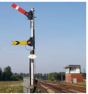
Figure 2.2: Modern Railroad Semaphore
So how did this system transfer to the road? In London, England in 1865 there was a growing concern over the amount of horse-drawn traffic causing danger to pedestrians trying to cross the roads. A railway manager and engineer named John Peake Knight, who specialized in designing signaling systems for the British railway, approached the Metropolitan Police with the idea of using a similar semaphore/lighted system for road traffic. In the daytime, this semaphore method used an arm or arms that could be raised or lowered by a police officer, notifying carriages when they should stop when the arm(s) stuck out sideways. At night, his system used the red and green colors to indicate the same type of thing, again traditional to the railroads.
His proposal was accepted and, on December 10, 1868, the system was put in place at the junction of Great George and Bridge Street in London, near Parliament. The system worked extremely well… for about a month. That’s when one of the gas lines that supplied the lights began to leak. Unfortunately, the policeman who was operating the arm was unaware of the leak and ended up being severely burned when the lamp exploded. Thus, despite its early success, the semaphore traffic system was immediately dropped in England.
On the other side of the pond, signaling traffic in the United States also used policemen as it was thought that people would not follow a set of rules unless there was some form of law enforcement present. Towers that allowed officers a better view of the traffic became commonplace in the 1910s and 1920s. During this time,
officers could either use lights (usually red and green after the railroad system), semaphores, or simply just wave their arms to let traffic know when to stop or go.
In 1920 in Detroit Michigan, a policeman named William L. Potts invented the four-way, three-color traffic signal using all three of the colors now used in the railroad system. Thus, Detroit became the first to use the red, green, and yellow lights to control road traffic. Many inventors continued to come up with different designs for traffic signals, some adopting the red, yellow, green color scheme and some not. Most usually needed a person to push a button or flip a switch to change the light. As you might expect, this man-power intensive way to change the lights proved costly.
In the late 1920s, several “automatic” signals were invented. The first ones used the simple method of changing the lights at specific timed intervals. However, the drawback of having some vehicles stopped when there were no cars going in the other direction annoyed people. An inventor named Charles Adler Jr. had an idea to get around this problem. He invented a signal that could detect a vehicle’s horn honking. A microphone was mounted on a pole at the intersection and once the vehicle stopped, all they need do is honk their horn and the light would change. To keep people from continually honking to get the light to change, and thus causing havoc, once the light was tripped, it wouldn’t change again for 10 seconds, allowing at least one car to get through. Presumably this system was incredibly annoying to people walking by and to nearby homes and businesses.
A less annoying automatic signal was invented by Henry A. Haugh. This system used two metal strips that sensed pressure. When a passing car pushed the two strips together, the light would soon change to allow that car to go.
All of these different types of lighting systems began to present a problem. Drivers could drive through different areas and encounter several different types of systems, causing confusion and frustration. So, in 1935, the Federal Highway Administration created “The Manual on Uniform Traffic Control Devices.” This document set uniform standards for all traffic signals and road signs.
2.3 Pedestrian Crossings
A pedestrian crossing or crosswalk is a place designated for pedestrians to cross a road. Crosswalks are designed to keep pedestrians together where they can be seen by motorists, and where they can cross most safely across the flow of vehicular traffic.
Marked pedestrian crossings are often found at intersections, but may also be at other points on busy roads that would otherwise be too unsafe to cross without assistance due to vehicle numbers, speed or road widths. They are also commonly installed where large numbers of pedestrians are attempting to cross (such as in shopping areas) or where vulnerable road users (such as school children) regularly cross. Rules govern usage of the pedestrian crossings to ensure safety; for example, in some areas, the pedestrian must be more than halfway across the crosswalk before the driver proceeds.
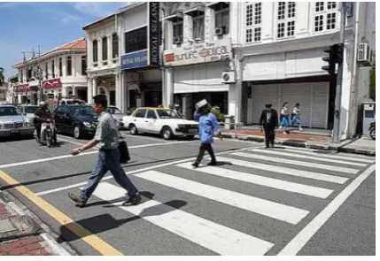
[image:24.595.190.405.552.699.2]Signalized pedestrian crossings clearly separate when each type of traffic (pedestrians or road vehicles) can use the crossing. Unsignalized crossings generally assist pedestrians, and usually prioritize pedestrians, depending on the locality. What appear to be just pedestrian crossings can also be created largely as a traffic calming technique, especially when combined with other features like pedestrian priority, refuge islands, or raised surfaces.
Figure 2.3: Pedestrian crossing in Malaysia