DESIGN OF ADJUSTABLE WHEEL NUT REMOVER
WAN MUHAMMAD ASRI BIN MOKHTAR
UNIVERSITI TEKNIKAL MALAYSIA MELAKA
WAN M UH D ASRI M OK HT AR B AC HE L
OR OF M
ECHAN ICA L E NGINEE RIN
G (
AU
T
OMOT
IVE
)(HONS.) 2015
UTe
SUPERVISOR’S DECLARATION
“I hereby declare that I have read this thesis and in my opinion this report is sufficient in term of scope and quality for the ‘Final Year Project’ as required.”
Signature: ………...
Supervisor: MOHD TAUFIK BIN TAIB
ii
DESIGN OF ADJUSTABLE WHEEL NUT REMOVER
WAN MUHAMMAD ASRI BIN MOKHTAR
This report is submitted in fulfilment of the requirements for the degree of Bachelor of Mechanical Engineering (Automotive)
Faculty of Mechanical Engineering Universiti Teknikal Malaysia Melaka
UNIVERSITI TEKNIKAL MALAYSIA MELAKA
iii
DECLARATION
“I hereby declare that the project is based on my original work except for quatations and citations which have been duly acknowledged.”
Signature: ………...
Author: MOHD TAUFIK BIN TAIB
iv
Special for
Beloved mother and father
Wan Faizah binti Mohammad Yusoff
Mokhtar bin Abdullah
Beloved partner
Su’amira binti Ibrahim
Beloved siblings
Supervisors
v
ACKNOWLEDGEMENT
Alhamdulillah, first and foremost I would like to thank Allah The Almighty who gave me the courage and the immense strength to perceive through all sorts of difficulties until this research work was completed. The hardship that I have experienced will never be forgotten.
Secondly, I would like to extend my gratitude to both of my parents, Mokhtar bin Abdullah and Wan Faizah bin Mohammad Yusoff for empowering their blessing throughout this project. I would also like to thank my life partner, Su’amira binti Ibrahim who was always enthusiastic and motivated me to complete my dissertation.
I would like to thank especially my supervisor, Mr. Mohd Taufik bin Taib who encouraged me and never hesitated to help me out during my study. I wish to express my warm and sincere gratitude towards him who encouraged and guided me throughout my research study.
vi
ABSTRAK
vii
ABSTRACT
viii
TABLE OF CONTENTS
CHAPTER CONTENTS PAGE
DECLARATION i
DEDICATION iv
ACKNOWLEDGEMENT v
ABSTRAK vi
ABSTRACT vii
TABLE OF CONTENTS vii
LIST OF TABLES xii
LIST OF GRAPH xiii
LIST OF FIGURES xiv
LIST OF SYMBOLS xvi
ix
CHAPTER 1 INTRODUCTION 1
1.1 Introduction 1
1.2 Problem Statement 2
1.3 Objectives 2
1.4 Scope 3
CHAPTER 2 LITERATURE REVIEW 4
2.1 The Existing Product 5
2.2 Wrench 6
2.2.1 Impact wrench 6
2.2.2 L-shaped wrench 7
2.2.3 Socket wrench 7
2.3 Theory of Tire 8
2.3.1 Bolt pattern 9
2.3.2 Pitch Circle Diameter (PCD) 9
2.3.3 Offset 11
2.3.4 Size of wheel 12
2.3.5 Centre bore 13
2.4 Chain Drive System 14
2.4.1 Roller chain 15
x
CHAPTER 3 METHODOLOGY 16
3.1 Flowchart 16
3.2 The Selection of Conceptual Design 17
3.3 Proposal of Basic Sprocket Design 18
3.3.1 Design 1 18
3.3.2 Design 2 19
3.3.3 Design 3 20
3.4 Pugh Method of Valuation 21
3.5 Chain Design 23
3.6 Parts Assembly 23
3.7 Fabrication Process 25
CHAPTER 4 RESULT AND ANALYSIS 28
4.1 Preliminary Result 28
4.1.1 Gear Ratio 28
4.2 Force and Torque Analysis 29
4.2.1 Force Applied by using L-shaped Wrench 30
4.2.2 Force Applied by using Extended L-shaped Wrench 31
4.3 Duration 32
4.4 Design Analysis 33
xi
4.4.2 Displacement 34
4.5 Safety Factor 36
CHAPTER 5 DISCUSSION 37
5.1 Introduction 37
5.2 Direction of Gears Rotation 38
5.3 Cost 38
5.4 Weight 40
5.4 Air Gun Application 41
5.5 Direct Comparison 42
CHAPTER 6 CONCLUSION AND RECOMMENDATION 43
6.1 Conclusion 43
6.2 Recommendation 44
6.2.1 Cost and Weight 44
6.2.2 Mechanical Properties 45
6.2.3 Selection of Material 46
6.2.4 Method used for Adjustment Process 47
REFERENCES 48
xii
LIST OF TABLES
NO. TITLES PAGE
2.1 Pitch Circle Diameter and Bolts Arrangement 9
3.1 Pugh Method of Valuation. 21
4.1 Average Torque of a Vehicle 29
4.2 Total Force Applied for Different Length of L-shaped 32
Wrench
4.3 Time Taken using Manual Method 32
4.4 Time Taken using Adjustable Wheel Nuts Remover 33
Tool
5.1 Production Cost (existing product) 39
5.2 Production Cost (adjustable all-wheel nuts remover) 40
5.3 Direct Comparison between The Existing Product and The 42
Prototype
xiii
LIST OF GRAPH
NO. TITLES PAGE
6.1 Density versus Price 43
xiv
LIST OF FIGURES
NO. TITLES PAGE
2.1 Electrical Impact Wrench 5
2.2 L-shaped Wrench 6
2.3 Socket Wrench 7
2.4 Bolt Pattern with Four Wheel Nuts 8
2.5 Offset 10
2.6 Tire Identification 11
2.7 Centre Bore Position 12
2.8 Various Types of Roller Chain 13
2.9 The Basic Concept of Chain Drive System 14
3.1 Flowchart of the Project 16
3.2 Design 1 18
xv
3.4 Design 3 20
3.5 Roller Chain 22
3.6 Sketch Drawing of the Product 23
3.7 Actual Product 23
3.8 Cutting Process 24
3.9 Drilling Process 25
3.10 Measuring and Marking Process 26
4.1 0.22m L-shaped Wrench 29
4.2 1.0m L-shaped Wrench 30
4.3 Von Mises Stress Analysis 33
4.4 Displacement Analysis 34
xvi
LIST OF SYMBOLS
P = Pitch diameter
𝑀𝐺 = Gear ratio
𝑁𝐺 = Number of teeth of driver gear
𝑁𝑃 = Number of teeth of driven gear
F = Force
xvii
LIST OF ABBREVIATIONS
CATIA = Computer Aided Three-Dimensional Application
FYP = Final Year Project
PSM = Projek Sarjana Muda
TIG = Gas Tungsten Arc
1
CHAPTER 1
INTRODUCTION
As the standard of living in Malaysia has increased, most of the families have at least one vehicle, typically, a car, to move easily and quickly. As we all know, tire puncture is the most common problem happen in the car. With the increment of the number of cars on the road, the number of car’s problem due to tire failure has increased. In order to overcome this problem, the car is provided with a set of special tools, usually L-shaped nuts remover and jack for instance spare tire replacement.
2 1.1Problem Statement
As we all know, the most common problem encounter by driver is tire puncture. Lots of human effort and time are needed during the tire removal process. To minimize the problem all-wheel nut remover device is designed. All-wheel nut remover is a device that helps to reduce human effort in order to remove the wheel nuts. Instead of removing the nuts one by one, this device helps to remove all nuts at the same time. This will save a lots of time during the process of tire removal. The main problem of existing product of all-wheel nut remover is, it only designed to fix with one PCD size. So, this adjustable wheel nut remover is being designed to fix with flexible PCD size within its range (114mm to 118mm).
1.2 Objectives
These are the objectives to be achieve throughout this project. The objectives are arranged by its priority as stated below:
To improve function of existing product by providing more option of PCD sizes.
To reduce the human effort during the process of tire removal. This can be achieved by removing all nuts at the same time instead of removing the nuts one by one.
To design and fabricate a prototype of adjustable wheel nut remover. This can be
3 1.3Research Scope
4
CHAPTER 2
LITERATURE REVIEW
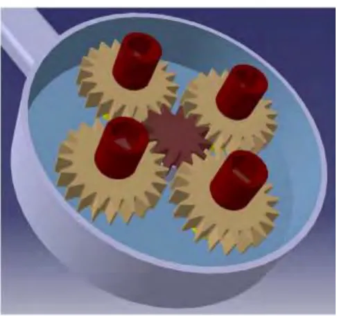
5 2.1 The Existing Product
[image:23.612.206.449.396.624.2]Some study has been done to the existing product in order to understand the concept, identify the problems that may be encountered by the existing product and to come out with a solution for the problem. Based on the study done on the existing product, it used the concept of gear mechanical as the basic mechanism. By only applying the force on the center gear (driver gear), all the driven gear will be moved by the driver gear but in the opposite direction. Further study about the conceptual design finally leads to the main problem of the product. In order to move the gears all together, all the gear teeth of the driven gear must be connected to the teeth of the driver gear. Any distance between them will cause product malfunction. These are the reason why the existing product only can fixed with one PCD size. Figure 2.1 shows the virtual conceptual design of the existing product.
6 2.2 Wrench
There are various types of wheel nut remover available in the market nowadays. Among the available wheel nut remover are impact wrench, L-shaped wrench, and socket wrench. The nuts itself also have various sizes such as 18mm, 19mm and 21mm. The shape of the head nut is hexagonal. In this project, a lot of research and study related to nut remover have been done.
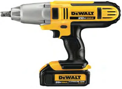
2.2.1 Impact wrench
[image:24.612.241.452.484.638.2]Impact wrench also known as impactor or pistol torque. It is a high power socket wrench which designed to produce high torque with minimum human effort, by storing the energy in the rotating mass and transmit it to external shaft. As the result, the nut will be tightened hard enough. Impact wrench basically used air, electric or hydraulic as the source of power. Figure 2.2 shows the available impact wrench available in the market.