UNIVERSITI TEKNIKAL MALAYSIA MELAKA
DESIGN AND DEVELOPMENT OF AUTONOMOUS ROBOT
USING DIGITAL FIBER OPTIC SENSOR
This report in accordance with requirement of the Universiti Teknikal Malaysia Melaka (UTeM) for the Bachelor Degree of Manufacturing Engineering (Robotic and
Automation) with Honour.
By
ABDUL MALIK YUSUF
FACULTY OF MANUFACTURING ENGINEERING
UNIVERSITI TEKNIKAL MALAYSIA MELAKA
BORANG PENGESAHAN STATUS TESIS*
JUDUL: “Design and Development Autonomous Robot Using Digital Fiber Optic Sensor”
SESI PENGAJIAN: 2009-2010
Saya ABDUL MALIK BIN YUSUF
mengaku membenarkan tesis (PSM/Sarjana/Doktor Falsafah) ini disimpan di Perpustakaan Universiti Teknikal Malaysia Melaka (UTeM) dengan syarat-syarat kegunaan seperti berikut:
1. Tesis adalah hak milik Universiti Teknikal Malaysia Melaka .
2. Perpustakaan Universiti Teknikal Malaysia Melaka dibenarkan membuat salinan untuk tujuan pengajian sahaja.
3. Perpustakaan dibenarkan membuat salinan tesis ini sebagai bahan pertukaran antara institusi pengajian tinggi.
4. **Sila tandakan (√)
SULIT
TERHAD
TIDAK TERHAD
(Mengandungi maklumat yang berdarjah keselamatan atau kepentingan Malaysia yang termaktub di dalam AKTA RAHSIA RASMI 1972)
(Mengandungi maklumat TERHAD yang telah ditentukan oleh organisasi/badan di mana penyelidikan dijalankan)
(ABDUL MALIK YUSUF)
Alamat Tetap:
48.Lorong 4,Taman Kuala Muda 08000 Sungai Petani
Kedah Darul Aman
Tarikh:12/04/2010_______________ __
Disahkan oleh:
(AHMADYUSAIRI BIN BANI HASHIM)
Cop Rasmi:
Tarikh: _______________________
DECLARATION
I hereby, declared this report entitled “Design and Development Autonomous Robot Using Digital Fiber Optic Sensor” is the results of my own research except as cited in references.
Signature : ...
Author’s Name : ABDUL MALIK YUSUF
APPROVAL
This report is submitted to the Faculty of Manufacturing Engineering of UTeM as a partial fulfillment of the requirements for the degree of Bachelor of Manufacturing Engineering (Robotic and Automation) with Honours. The member of the supervisory committee is as follow:
……… Supervisor
( Pn.Syamimi Binti Shamsudin) Faculty of Manufacturing Engineering
ABSTRACT
ABSTRAK
DEDICATION
ACKNOWLEDGEMENTS
Alhamdulliah, I would like to express my thankfulness to Allah S.W.T because has given me all the strength that I need in fulfilling and completing my Projek Sarjana Muda and selamat is upon to the Prophet Muhammad S.A.W. I would like to thank my supervisor Puan Syamimi Shamsudin for his constructive guidance encouragement and patient in fulfilling our aspiration in completing this project and also to my entire lecturers and technicians for their advice and motivation to development this project. I am especially thanks to my friends for their generosity in sharing information regarding to design and development of autonomous robot using digital fiber optic sensor.
TABLE OF CONTENT
Abstract i
Abstrak ii
Dedication iii
Acknowledgement iv
Table of Content v
List of Figure x
List of Table xiv
List of Abbreviation, Symbols, Specialized Nomenclatures xv
1.0 INTRODUCTION 1.1 Background 1
1.2 Problem Statement 3
1.3 Project Aim and Objectives 3
1.4 Scope 4
1.5 Robot Technology 4
1.5.1 Definition of Robot 4
1.5.2 History of robot 5
1.5.3 Revolution of robots 6
1.6 Project Planning 7
2.0 LITERATURE REVIEW 2.1 Introduction to Autonomous Robot 9
2.2 Electronics Background 10
2.3 Programming Background 11
2.4 Mechanical Background 12
2.5 Actuator 13
2.5.1 Principles of Operation 14
2.6.1 Alternating Current (AC) Motor 16
2.6.2 Direct Current (DC) Motor 17
2.6.3 Types of Direct Current (DC) Motor 17
2.6.4 DC geared Motor 19
2.6.5 Brushless Motor 20
2.7 Sensor 21
2.7.1 IR Sensor 22
2.7.2 Digital Fiber Sensor 23
2.7.3 Principles of Process 25
2.7.4 Benefit of Fiber Optic 27
2.7.5 Latest Development 28
2.8 Types of Robot Controller 29
2.8.1 PC Based 29
2.8.2 Microcontroller 30
2.8.3 Major supplier of Microcontroller 31
2.8.3.1 Atmel 31
2.8.3.2 Microchip 31
2.8.4 The PIC Microcontroller Family 31
2.8.4.1 PIC 16F 32
2.8.4.2 PIC 18F 32
2.9 Programming 33
2.9.1 Micro C Software 33
2.9.2 MPLAB Programming Software 34
2.10 Circuit Design Software 35
2.10.1 Proteus PCB Software 36
2.11 Robot Design Software 37
2.11.1 Solid Works 37
2.11.2 AutoCAD 39
2.12 Power Source 40
2.12.1 Basic Principles of Lead Acids Rechargeable Battery 41
2.13 Wheel 43
2.13.1 Nylon Wheel 43
2.13.2 Mecanum Wheel 44
2.14 Material for Mechanical Structure 46
2.14.1 Aluminum 46
2.14.2 Stainless Steel 47
2.15 Indirect Power Transfer Device 47
2.15.1 Belt 48
2.15.2 Plastic and Cable Chain 49
2.16 Features of the ROBOCON 2009 Autonomous Robot 50
2.17 ROBOCON Competition 51
2.17.1 The ROBOCON 2010 51
2.17.2 The Requirement for the ROBOCON 2010 Autonomous Robots 52
2.17.3 Universiti Teknologi Malaysia 55
2.17.4 Multimedia University Melaka 56
2.18 Similar Past Projects of Autonomous Robots 56
2.18.1 Development of Autonomous Robot to Collect Colored Objects 57
2.18.2 Structure of the Robot 59
2.18.3 Colored Takraw Ball Selector 59
2.17 Conclusion 59
3.0 METHODOLOGY 3.1 Development Phase 60
3.2 Phase 61
3.2.1 Planning Phase 62
3.2.2 Design and Development phase 63
3.2.3 Testing and Analysis 64
3.3 Data Collection 65
3.3.2 Journal and book 65
3.3.3 Internet 65
3.4.1 Base 66
3.4.2 Gripper 67
3.5 Software Development 68
3.5.1 Mechanical Software 68
3.5.2 PIC Programming Software 70
3.6 Project Tools and Equipment 75
3.7 Conclusion 78
4.0 DESIGN AND DEVELOPMENT 4.1 Conceptual Design Process 79
4.2 First Design 80
4.2.1 Advantages 81
4.2.2 Disadvantages 81
4.3 Second Design 82
4.3.1 Advantages 83
4.3.2 Disadvantages 83
4.4 Pugh Method for Design Selection 83
4.5 Development 85
4.5.1 Mechanical Structure 85
4.5.1.1 Base 85
4.5.1.2 Body 86
4.5.1.3 Center of Gravity 87
4.5.1.4 Gripper 89
4.5.1.5 Lifting Mechanism 90
4.5.1.6 Position of Fiber Optic Sensor 91
4.5.1.7 Wheel (Locomotion) 92
4.5.2 Electrical Circuit 92
4.5.2.1 Separate Voltage Circuit 95
4.5.2.2 Fiber Optic Sensor Connection 95
4.5.2.3 Motor Driver 98
4.5.3 Programming Algorithm 102
4.5.4 Bill of Material 107
5.0 TESTING, RESULTS AND DISCUSSION
5.1 Introduction 108
5.2 Line Following Test 109
5.3 Turning Test 110
5.4 Collated Cube Test 112
5.5 Result and Discussion 114
6.0 CONCLUSION AND RECOMMENDATION
6.1 Introduction 116
6.2 Conclusion 116
6.3 Recommendation 117
LIST OF FIGURE
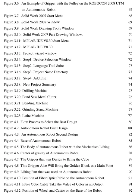
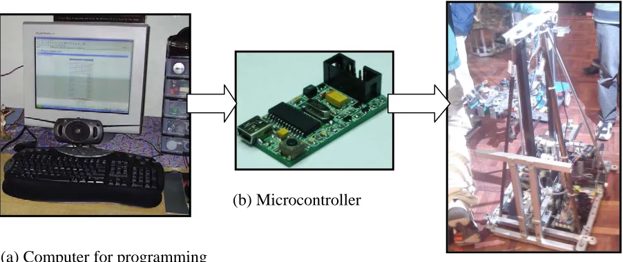
Figure 1.1: Basic Idea of the Project 2
Figure 1.2: Gantt chart for PSM1 7
Figure 2.1: An Example of an Autonomous Robot Using Color Sensor 9
Figure 2.2: The basic building blocks of a fully functional robot, including central 10
processor (brain), locomotion (motors), and sensors Figure 2.3: Basic Motor Construction with Internal Design 12
Figure 2.4: Magnetic Flux Lines Produce by a Permanent Magnet 14
Figure 2.5: The torque of motor is the rotary force produced on its output shaft 14
Figure 2.6: Typical DC Motor Construction 16
Figure 2.7: Concept of Direct Current Electromagnetism 17
Figure 2.8: An Example of DC Geared Motor 18
Figure 2.9: an Example of Brushless Motor 19
Figure 2.10: Electronic amplifier or drive which can also be used to do the commutation in response to low-level signals from an optical or hall-effect sensor. 20
Figure 2.11: An Example of IR Sensor 21
Figure 2.12: An Example of a Digital Fiber Sensor Manufactured by SICK 22
Figure 2.14: All Light that Strikes the Boundary between the Cores 24
Figure 2.15: The Operation of the Photonic Sensor 25
Figure 2.16: Sensor Reflected Light is Low Close to Target 25
Figure 2.17: Maximum Reflected Light from Fiber Optic Sensor 27
Figure 2.18: Omron's E3X-DAN incorporates a connector design that allows 16 28
Figure 2.20: An Example of PIC 16F 32
Figure 2.21: Micro Compiler Software 34
Figure 2.22: Main Window for MP Lab Software 35
Figure 2.23: Screen Shot Showing a Typical ISIS Design. 37
Figure 2.24: An Example of Solid Work Drawing32 38
Figure 2.25: An Example of Drawing by Using AutoCAD Software 39
Figure 2.26: Lead Acids Rechargeable Battery 40
Figure 2.27: Diagram of Charging of the Secondary Cell Battery 42
Figure 2.28: An Example of Mecanum Wheel Design 45
Figure 2.29: An Example of a Robot Using Aluminum as a Chassis 46
Figure2.30: An example Robot Use Stainless Steel to Support the Body 47
Figure 2.31: The Cross Sectional Shape of the Belt 48
Figure 2.32: Plastic pins eliminate the bead chain's tendency to cam out of pulley recesses, and permit greater precision in angular transmission 49
Figure 2.33: Autonomous Robot for ROBOCON 2009 50
Figure 2.34: Circuit and Motor Controller for Autonomous Robot 51
Figure 2.35: Mankuara Pyramid that for Autonomous Robot 2 52
Figure 2.36: The middle block and golden block with the fully dimension to assist student to make the best gripper design 53
Figure 2.37: The game field consists of two Automatic Zones and a Manual Zone and three Pyramids (Khufu, Khafraa and Mankaura) 55
Figure 2.38: Autonomous Robot from Univesiti Teknologi Malaysia 56
Figure 2.39: Autonomous Robot from Multimedia University (MMU) 57
Figure 2.40: The Base Frame and Drive Wheel 57
Figure 2.41: The Input Fin and Sucking Mechanism of the Robot 58
Figure 2.42: The Takraw Ball Shot in the Mechanism 58
Figure 3.1: Flow Chart of the Overall Project Process 61
Figure 3.2.: Flow chart of the Planning Phase 62
Figure 3.3: Flow Chart of the Design and Development Phase. 63
Figure 3.4: Flow Chart of the Testing and Analysis Phase 64
Figure 3.6: An Example of Gripper with the Pulley on the ROBOCON 2008 UTM
an Autonomous Robot 67
Figure 3.7: Solid Work 2007 Start Menu 68
Figure 3.8: Solid Work 2007 Window 69
Figure 3.9: Solid Work Drawing Tools Window 69
Figure 3.10: Solid Work 2007 Part Drawing Window. 70
Figure 3.11: MPLAB IDE V8.30 Start Menu 71
Figure 3.12: MPLAB IDE V8.30 71
Figure 3.13: Project wizard window 72
Figure 3.14: Step1: Device Selection Window 72
Figure 3.15: Step2: Language Tool Suite 73
Figure 3.16: Step3: Project Name Directory 73
Figure 3.17: Step4: Add File 74
Figure 3.18: New Project Summary 74
Figure 3.19: Drilling Machine 75
Figure 3.20: Band Saw Metal Cutter 76
Figure 3.21: Bending Machine 76
Figure 3.22: Grinding Stand Machine 77
Figure 3.23: Lathe Machine 77
Figure 4.1: Flow Process to Select the Best Design 80
Figure 4.2: Autonomous Robot First Design 80
Figure 4.3.: An Autonomous Robot Second Design 82
Figure 4.4: Base of Autonomous Robot 85
Figure 4.5: The Body of Autonomous Robot with the Mechanism Lifting 86
Figure 4.6: Center of gravity of Autonomous Robot 88
Figure 4.7: The Gripper that was Design to Bring the Cube 89
[image:16.612.101.539.67.714.2]Figure 4.8: This Gripper Also Will Bring the Golden Block as a Main Point 89
Figure 4.9: Lifting Part that was used on Autonomous Robot 90
Figure 4.10: Position of Fiber Optic Cable on the Autonomous Robot 91
Figure 4.11: Fiber Optic Cable Take the Value of Color as an Output 91
Figure 4.13: Flow Process to Make Electronics Circuit 93
Figure 4.14: Printing Artwork before Etching Process 94
Figure 4.15: Drilling Process with Hold Steadily and Straight Slowly 94
Figure 4.16: Separate Voltage Circuit 95
Figure 4.17: Teach Pendant to Setup the Value and Tune the Color 96
Figure 4.18: 3 Wires that was shown Positive, Ground and Signal Cable 96
Figure 4.19: Sensor in On Position 97
Figure 4.20: Motor Driver with Board Layout 98
Figure 4.21: Board Controller with Board Layout 100
Figure 4.22: Subprogram for Line Following: Defining Variables 103
Figure 4.23: Subprogram for Line Following: Programming for the Sensor 104
Figure 4.24: Subprogram for Line Following: Programming for the Sensor 105
Figure 5.1: Game Field for Mankaura Pyramids 108
Figure 5.2: Autonomous Robot Move Straightly Follow the Line 109
Figure 5.3: Autonomous Robot Brought the Cube to Put on the Pyramid 110
Figure 5.4: Autonomous Robot turns right Guide by Fiber Optic Sensor 111
Figure 5.5: Autonomous Robot put the Main Block 112
Figure 5.6: Autonomous Robot put the Golden Block 113
LIST OF TABLE
Table 4.1: Final Pugh Chart to Obtain the Best Design. 78
Table 4.2: Label and the Function of the Part Layout 99
Table 4.3: Label and the Function of the Part Layout 101
LIST OF ABBREVIATION, SYMBOLS, SPECIALIZED
NOMENCLATURES
LDR - Light Dependent Resistor ROS - Robot Operating System AC - Alternating Current DC - Direct Current IR - Infrared
NDIR - Non Dispersive Infrared CPU - Central Processing Unit RAM - Random Access Memory I/O - Input/Output
RF - Radio Frequency SOC - State Of Charge
CHAPTER 1
INTRODUCTION
Today, robot is widely used in industrial manufacturing. It is usually an electro-mechanical system which, by its appearance or movements, conveys a sense that it has agency of its own.
1.1 Background
The word of robot can refer to both physical robots and software, but the latter are usually refer to as bots. There is no agree on which machines qualify as robots, but there is general agreement among experts and the public that robots toward to do some or all of the following move around, operate a mechanical limb, sensor and manipulate it environment, and exhibit intelligent behavior, especially behavior which like humans or other animals.
Autonomous robots are robots which can perform by following tasks and complete it without human control and workforce. Autonomous robot many advantages more than manual robot and it ability to get information about the environment and things, and it can work extended period without human, it also can avoid situations that are harmful to people, property, or itself and work danger situation that human cannot be perform and complete it more fast than human.
(b) Microcontroller
(a) Computer for programming
[image:21.612.113.564.223.413.2](c) Autonomous Robot
1.2 Problem Statement
The idea to design and develop comes from when task was given in ROBOCON 2010. One must have strong basic in three main aspects of engineering like mechanical, electrical and electronics, and programming in order to complete this project. The autonomous robot use LDR sensor and it need to adapt to low contrast situation and it will to pick up the reflect light but slower to respond. That problem can be solved by using digital fiber optic sensor for autonomous robot to produce an efficient, precise and high speed robot platform to carry out the competition tasks within an optimum timeframe.
1.3 Project Aim and Objectives
The aim of this project is to produce an efficient, precise and high speed an autonomous robot platform to carry out the competition tasks within an optimum timeframe. In order to verify the aim and project as a success, these three objectives must be achieved:-
a) To design and develop mechanical structure of an autonomous robot and that will utilize fiber optic sensor to carry out its line following task.
1.4 Scope
Projectscopes are important in order to help in the development and the progress of the project. This project will focus on the design and develop of an autonomous robot using color sensor and PIC microcontroller in order to perform its specified task. Not only those, scopes also help in deciding the path and secure the flow of the project.
This project will focus on design and development an autonomous robot using color sensor to perform its specific tasks. To design and develop mechanical structure it has to select the superior material to make a light and secure robot. Then, the robot is in motion by programming to develop electronic circuit using microcontroller and it also focus on interfacing between mechanical system and electronic circuit.
1.5 Robot Technology
While most robots today are installed in factories or homes, performing labor or life saving jobs, many new types of robot are being developed in laboratories around the world. Much of the research in robotics focuses not on specific industrial tasks, but on investigations into new types of robot, alternative ways to think about or design robots, and new ways to manufacture them
1.5.1 Definition of Robot
The definition is very limiting in that includes neither mobile robot type of science fiction character that would call an android. Perhaps a comprehensive definition would be McKerrow’s (1986) and robotics is the discipline that involves:-
a. The design, manufacture, control and programming of robots. b. To use of robot to solve problems.
c. The study of the control processes, sensor, and algorithms used in humans, animals, and machine.
d. The application of these control processes and algorithms to the design of robots.
1.5.2 History of robot
The word ‘Robot’ entered the English language through a Czechoslovakian play title Rossum’s Universal Robot, written by Karel Capek in the early 1920s. The Czech word” Robota” means forced worker. In the English translation, the word was converting to “Robot”. The story line of the play centered on a scientist name Rossum who invent a chemical material similar and used it to produce robots. The scientist goal is for robots to serve humans and perform physical labor. Rossum continues to make improvement in his invention, ultimately perfecting it. These perfect beings begin to resent their passive role in society and turn against their masters (Groover 2001).