2 University of Liverpool, Department of Engineering
Novel, Induced-Flow, Centrifugal Water
Pumping System for Off-Grid Application
Thesis submitted in accordance with the requirements of the University of
Liverpool for the degree of Doctor in Philosophy
By
Neale Davies
i
Dedication
ii
Abstract
Water provision in rural areas represents a significant challenge, especially within the context of resource and sanitation in developing countries. High set-up costs, lack of installation expertise and reliability issues, arising from fluctuating operational conditions, have prevented many people from receiving the full benefit of automated pumping systems. The specific aim of this thesis is to assess the feasibility of using a tunable, induced flow subsystem as a means of optimising the power utilization and performance of a centrifugal pump over a wider range of operating conditions than typically expected. More generally, the research presented is undertaken to reduce the high implementation costs and localised limitations of rural water pumps by developing the theory towards a ‘’one-size-fits-all’’ pumping system.
The theoretical analysis of an induced flow centrifugal pumping system is presented, coupled with the analogous electrical system. The results of simulations performed using both systems are compared to experimental results, obtained using an induced flow subsystem (IFS) test rig constructed at the University of Liverpool. All sets of results demonstrate consistent IFS characteristics, identifying its capability to maintain maximum power point (MPP) operation of the centrifugal pump irrespective of load. Further, the experimental results reveal a boost in output pressure which enables the pump to achieve an improved hydraulic power and increased operating range over the same system without an IFS.
iv
Acknowledgements
First and foremost, my thanks go to Drs. Tim Short and Mark Johnson for their supervision throughout this PhD. In particular, I would like to express my gratitude to Dr. Tim Short, for his guidance, encouragement and eternal optimism throughout my research. A mention also goes to Dr. Aram Hassan for his work with Dr. Short. My thanks also go to the sustainable research team for their encouragement and (overoptimistic) belief in my research. In particular, a mention must go to Ms. Ruth Sutton for her continual provision of interesting discussions and debates over new ideas and research projects.
I gratefully acknowledge the EPSRC and University of Liverpool for providing my main source of funding throughout my studies. Additional thanks go to the University for its Facilities and excellent academic support staff, in particular Ms. Denise Stewart and Mr. Jack Carter-Hallam.
My express thanks go to all my family and friends for all their support and many adventures. Thanks to my Granddad for humouring me with talks about fantastical valve operation mechanics and enlightening me on several areas of electrical engineering. Particular mentions go to Dave, Ed and Helen for sticking around from the beginning; Carl, Phil and Nicki for providing excellent musical distractions from work; Alison, Vera and Mark for their belief in me; Alastair and Patrick for their understanding; and Mark Croft for his wisdom. Of course, none of my endeavours to date have been possible without the encouragement of my parents.
v
Publications
1. Davies N, Short T.D, Hassan A, Optimizing photovoltaic water pumping systems for developing countries through the addition of a novel induced flow subsystem, Renewable Energy in the Service of Mankind Vol II 1,47, Springer International Publishing, Switzerland (Due for publication, 2016)
Presentations at Conferences
vi
Contents
Abstract ... ii
Acknowledgements ... iv
Publications ... v
Presentations at Conferences ... v
Nomenclature ... xiv
Abbreviations ... xvii
Chapter 1 - Introduction
... 11.1 Access to Water in Remote Areas ... 1
1.2 The Thesis ... 2
1.2.1 The Research Hypothesis ... 2
1.2.2 Research Impact ... 4
1.3 Research Aim ... 5
1.4 Project Objectives ... 6
1.5 Thesis Structure ... 6
1.6 Summary ... 7
Chapter 2 – Off-Grid Water Pumping
... 82.1 Introduction to off-grid Water Pumping ... 8
vii
2.2.1 Water Resource and Social Development... 11
2.3 The Pumping System ... 14
2.3.1 The Controller ... 15
2.3.2 The Battery/Reservoir ... 15
2.3.3 The Pump Motor ... 16
2.4 Off-Grid Power Supply ... 20
2.4.1 Diesel Powered Pumps ... 20
2.4.2 Solar Pumps ... 21
2.4.3 PV Optimisation ... 22
2.4.4 Direct Coupling ... 24
2.4.5 Wind Turbine Pumps ... 25
2.5 Cost... 25
2.6 Types of Pump ... 27
2.6.1 Reciprocating Pumps ... 28
2.6.2 Helical Pumps ... 29
2.6.3 Centrifugal Pumps ... 31
2.7 Limitations to Current Technology ... 34
2.7.1 Operating Conditions ... 34
2.7.2 Borehole Dynamics ... 35
viii
2.7.4 Power Utilization ... 36
2.7.5 Appropriate Technology? ... 37
2.9 An Ideal Pumping System? ... 38
2.10 Summary ... 39
Chapter 3 – Induced Flow Pumping
... 413.1 Induced Flow in Reciprocating Pumps ... 41
3.2 The Hydraulic Ram ... 44
3.3 Electric-Hydraulic Analogy ... 46
3.3.1 The DC-DC Boost-Converter ... 46
3.3.2 Centrifugal Water Pump with Pressure Boost ... 47
3.4 Summary and Conclusions ... 48
Chapter 4 – The Pumping System
... 504.1 Mathematical Model ... 51
4.2 System Analysis ... 52
4.2.1 The Inductance Pipe ... 52
4.2.2 The Capacitance Chamber ... 54
4.1.3 The Electronic Control Valve (ECV) ... 56
4.3 Best Efficiency Point Tracking ... 57
4.3.1 Valve Opening Period ... 59
ix
4.3.3 Best Efficiency Vs Output Flow ... 65
4.4 Summary ... 65
Chapter 5 – Characteristic Equations
... 675.1 Defining flow ... 68
5.2 Defining Inductance Flow ... 69
5.2.1 Additional Definition of Duty ... 72
5.3 Validation Of The Position Of Average Flow ... 74
5.4 Theoretical Limit on Pumping Head ... 75
5.5 Time Condition 1: ECV (ON) ... 76
5.6 Time Condition 2: ECV (OFF) ... 81
5.7 Constants of Integration ... 84
5.7.1 Boundary Condition 1 ... 85
5.7.2 Boundary Condition 2 ... 85
5.7.3 Boundary Condition 3 ... 86
5.7.4 Boundary Condition 4 ... 86
5.7.5 Solving for Constants of Integration ... 87
5.5 Summary ... 88
Chapter 6 – Numerical Analysis
... 896.1 Equations of Flow ... 89
x
6.2.1 Improved Discharge Flow ... 91
6.2.3 Inductance and Discharge Flow Trends ... 94
6.3 Pump Stability ... 98
6.3.1 Output inductance ... 101
6.4 Computational Testing ... 103
6.4.1 Test Parameters ... 105
6.5 Conclusions ... 108
Chapter 7 – Electrical Analysis
... 1097.1 The Electrical Circuit ... 109
7.1.1 Component Definitions ... 112
7.2 MicroCap Simulations ... 115
7.2.1 Inductance and Discharge Flows ... 115
7.2.2 Flow Stability ... 119
7.2.3 Decoupling of Current Source ... 121
7.3 Discussion and Conclusions ... 123
Chapter 8 – Experimental Analysis
... 1258.1 Experimental Limitations ... 125
8.1.1 ECV Operation Time ... 125
8.1.2 Laboratory Space ... 126
xi
8.2 Induced Flow Subsystem Setup ... 127
8.2.1 The Inductance Pipe ... 129
8.2.2 Electronic Control Valve (ECV) ... 130
8.2.3 Capacitance Chamber ... 132
8.2.4 Adjustable Head Assembly ... 133
8.3 Lumped Parameter Analysis ... 135
8.4 Instrumentation ... 136
8.4.1 Average Discharge Flow Measurement ... 136
8.4.2 Inductance Pipe Flow Measurement ... 136
8.4.3 System Pressure ... 138
8.4.4 ECV Position Measurement ... 139
8.4.5 Data Acquisition ... 140
8.5 Data Manipulation ... 142
8.6 Performance Test Results ... 144
8.6.1 Discharge Flow ... 144
8.6.2 Frequency Ratio and Discharge Flow ... 147
8.6.3 ECV Constant Duty ... 150
8.6.4 Hydraulic Power Output... 151
8.6.5 Pumping System Efficiency ... 154
xii
8.6.7 Experimental and Theoretical Comparison ... 160
8.6.8 Average Inductance Flow ... 162
8.7 Conclusions ... 166
Chapter 9 – Conclusions an Outlook
... 1689.1 General Summary ... 168
9.2 Project Aim and Objectives ... 173
9.3 General Conclusions ... 175
9.3.1 Pump BEP Operation ... 175
9.3.2 IFS Pump Output ... 176
9.3.3 ECV operation ... 176
9.3.4 Power Utilisation ... 177
9.3.5 Potential Applications ... 178
9.4 Future Work/Considerations ... 179
9.5 Concluding remarks... 181
References ... 183
Appendix A – The Timed ECV
... 192A.1 Defining the Duty Cycle ... 192
Appendix B – Discharge Flow Boundary Conditions
... 199xiii
B.2 Defining the Constants of Integration ... 200
B.2.1 Finding the Final Constant ... 201
B.3 Summary ... 206
Appendix C – Flow Data and Experimental Analysis
... 207C.1 Pump Characteristics and ECV Operation ... 207
C.2 Experimental Procedure ... 211
C.2.1 Setting the Test Head ... 211
C.2.2 Priming the Pumping System ... 212
C.2.3 Programming the ECV and system Duty ... 212
C.2.4 Collecting Flow Data ... 213
C.3 Data Manipulation ... 215
C.4 Experimental Discharge Flow Data ... 220
C.5 Instantaneous Flow Data ... 228
C.5.1 Frequency Ratio, r = 2 ... 230
C.5.2 Frequency Ratio, r = 1.5 ... 238
xiv
Nomenclature
Symbol
Definition
Units
Internal Pipe Cross Sectional Area Electrical Capacitance
Duty -
Modulus of Elasticity Force
Head Current
Hydraulic Softness/Compressibility
Inductance
Electrical Inductance
Mass
Pressure
Pressure Difference
Flow Rate
Change in Flow Rate
Time Period
Voltage Acceleration Wave Celerity Diameter Pipe Thickness
xv
Frequency
Acceleration Due To Gravity Mechanical Stiffness Length
Dimensionless ratio of Inductance
-
Mass Flow Rate Dimensionless Frequency Ratio -
p Power W
Change in Length
t Time
u Velocity
Volume
Constant of Flow
Constant of Flow Bulk Elasticity Modulus Pump Efficiency -
Fluid Density Angular frequency System Natural Frequency
Flow Ripple -
Subscripts
relating to the average value
xvi
relating to the discharge pipe denotes electrical term
relating to the electronic control valve
denotes hydraulic term
K relating to the capacitance chamber
relating to the inductance pipe
denotes maximum value
denotes minimum value
Relating to ECV inactive period
Relating to ECV active period
relating to the one-way valve
xvii
Abbreviations
AC – Alternating Current
BEP – Best Efficiency Point
ECV– Electronic Control Valve
DC – Direct Current
IFS – Induced Flow Subsystem
MDG – Millennium Development Goals
MPP – Maximum Power Point
NTIofV – Nonlinear transfer function component (Current to Voltage)
OWV – One-Way Valve
PV(P) – Photo Voltaic (Pump)
SELF – Solar Electric Light Fund
UoL – University of Liverpool
1
Chapter 1
- Introduction
Introduction
1.1
Access to Water in Remote Areas
Water supply and sanitation in rural areas (particularly in developing countries) represents an issue affecting almost a third of the global population. Pumping systems utilising off-grid power sources can be one way of providing access to water where connection to a grid power supply would otherwise be impossible or too expensive. Such systems include the use of diesel generators, or more suitably, sustainable power systems.
2 pumping system for providing a supply of a resource which is vital to any community or persons living/working in a rural area: clean water.
1.2 The Thesis
Clean water is a resource which is vital for both domestic and industrial applications. Sustainable water pumps such as those involving photovoltaic (PV) or wind power sources can be one way of providing a clean, sustainable water source for drinking, sanitation, irrigation and agriculture [1] - but they are not without their flaws. Targets set nearly 3 decades ago to implement 10 million PV pumps [2] saw only 0.6% of this figure realized by the end of the 20th century [3], many of which had been shown to be non-operational by 2001 [4]. Reasons for failing to reach this target could be through various problems with pump design, component reliability or the implementation cost per unit. One way of combating these problems would be to introduce a means for an existing pumping system to self-regulate – compensating for any fluctuations in operating conditions and thereby improving the reliability of discharge flow from the pump by optimising the use of power to the system. Such a system would also lend itself to an auto-setup capability, eliminating the need for site specific assessment which in turn would lower the cost of installing a single unit; a factor which is deemed extremely important in the provision of access to water in rural areas [5, 6]. In essence, a system capable of both auto-setup and self-regulations would effectively be a one-size-fits-all pump.
1.2.1 The Research Hypothesis
4 Given this information, it is possible to state that the research hypothesis is therefore:
‘’The use of an IFS can ensure that the centrifugal pump is itself
operating at its MPP (BEP) thereby decoupling its operation from the conditions
around it.’’
1.2.2 Research Impact
Although this research project is primarily focused on the furthering of sustainable pumping systems and developing the theory towards a novel centrifugal pumping system, the research will potentially have an impact on a wider range of areas within the academic community. Some of these areas include:
Utilization of a novel induced flow subsystem; expanding the application of centrifugal pumps for sustainable borehole pumping, benefiting not only PVP’s but also Diesel, wind and hybrid energy powered, off-grid, pumping systems.
Development in the field of fluid dynamic theory of systems involving centrifugal pumps; beneficial to both the fluid dynamics and hydraulic engineering communities.
Furtherance of research into the need for sustainable water pumping methods within a global context; beneficial to sanitation and resource academics.
Continued research into the novel area of PV pumping systems and their uses in both developing countries and rural areas in need of reliable water supply.
5 Furthermore, the development of a new form of PV pumping system could hold potential benefits for ‘real world’ use outside of academia, where:
The implementation cost of sustainable borehole pumping units will be lowered due to the removal of site-specific assessments.
The use of a tuned hydraulic system will expand the application of centrifugal pumps within the context of sustainable borehole pumping, allowing for pump performance across a wider range of conditions – equating to a more stable supply of water in rural areas.
This research marks a step towards an “auto-setup”, “one-size fits all”, sustainable pumping system.
1.3
Research Aim
6
1.4
Project Objectives
The following objectives were identified as a means of ensuring that the project realizes the specific aim outlined previously:
Develop an analytical theory, considering in detail the validity of the assumptions made in the project proposal.
Use the analytical theory to produce a numerical study into the pumping systems operation under varying hydraulic conditions.
Compare any analytical theory to existing electrical theory on the use of boost-converters in order to validate the electric-hydraulic analogy for this research.
Design and manufacture a centrifugal pump test bed as a means of assessing the accuracy of the computational model and hence analytical theory.
Use the centrifugal pump test bed with the addition of the tuned hydraulic system to obtain performance data for the modified system.
Compare all set of data from analytical to experimental as a means of providing evidence of any performance improvements with the tuned hydraulic system.
1.5
Thesis Structure
The thesis itself is broken down into 9 Chapters. Each chapter attempts to take a logical progression through the individual stages of the research project and finally arrive at a concluding chapter which discusses some of the findings of the research and poses future research questions. The project was divided into 4 main stages, reflected in the chapter choices. These stages are as follows:
7 2. Theoretical analysis and design of the pumping system (Chapters 4 and 5). 3. Numerical and electrical analysis of the pumping system (Chapters 6 and 7). 4. Experimental testing and analysis (Chapter 8).
The chapters are arranged in such a way so as to provide the clearest narrative and to introduce new themes and ideas as they become relevant. It is also noted that the research was intended primarily to be a feasibility study into the broader aspects of the novel pumping system designed.
1.6 Summary
8
Chapter 2
– Off-Grid Water Pumping
Off-Grid Water Pumping
This chapter covers a broad range of literature surrounding water pumping in rural areas. This stretches from the background surrounding the research, such as the need for reliable water supplies in off-grid locations, to the types of pump currently available and the benefits and drawbacks of each (highlighting the relevance of this research). Although the developed novel pumping system is able to operate with any of the range of power systems available for off-grid use, the wealth of literature concerning sustainable systems (such as those based on the use of PV, wind or hybrid energy) has led much of the research presented to be focused on these systems (in particular PVP’s).
2.1 Introduction to off-grid Water Pumping
9 expense of connection to a grid-supply or simply through impracticality. The World Bank predicts a global population growth of 2.5 billion within the next 35 years and the global share in population for developing countries to rise from 85% to 88% [21], further expanding this issue. In these areas, water demands are met by employing pumping systems which rely on power sources that are suitable for off-grid use. The pumping systems can range from simple manual hand pumps, to automated electrical pumps [2, 22]. Of the electrical systems, sustainable power sources such as PV panels and wind turbines have been the focus of much study in recent past due to their effectiveness and suitability of operation in remote locations. This is coupled with their lower lifetime costs in comparison to a standard fuel based pumping system, which require regular access to fuel and continued maintenance.
As the majority of this body of work will be considering the performance of a novel pumping system and its relevance in relation to existing pumping systems (in particular sustainable ones), it is first necessary to consider the reasons behind the need for sustainable pumping systems and indeed, the need for clean water itself.
2.2 Sanitation and Water Resource in Developing Communities
10 and face, and keeping the body and clothes in contact with the body free of dirt, bacteria and other parasites. The average adult requires around 3 litres of drinking water per day for hydration, which is relatively minimal when compared to the additional 17 litres of water needed to cover the most basic needs of a single person; as suggested by the World Health Organization (WHO) [25]. Furthermore, the spread of disease due to unclean water supply does not stop at its consumption or use for sanitation. Water-related disease and transfer may be split into several categories [24], more commonly referred to as ingested, washed, sourced and aerosol diseases:
Waterborne disease – The classification for disease spread through the ingestion of contaminated water. Most commonly this includes diarrheal diseases, but also includes parasitic infection that causes serious illness.
Water-washed disease - Diseases spread through lack of clean water for personal hygiene, usually contagious or diarrheal diseases that are easily spread from person to person. Simply having contact with dirty water supplies whilst washing clothing or the body is enough for infection.
Water-based diseases – Arising from disease carrying organisms which require water as part of their life cycle, often transferring these diseases to human hosts when the water is used for washing.
11 In the year 2000, the United Nations introduced a series of millennium development goals (MDG’s) to address access to clean water for drinking and sanitation purposes in an effort to reduce the global mortality rates from water related diseases [26]. In 2015, the UN released a report which stated that the number of people without access to clean and sustainable water sources had been halved (as part of target 7C of the MDG’s [27]). There is, however, still a reported 2.4 billion without this facility. It was previously estimated that if no measure was taken to address this basic unmet need that as many as 135 million people would have died from disease caused by a lack of clean water within the first two decades of the 21st century [24] – largely contributed to by deaths due to diarrheal based diseases alone. The same study concluded that even if many of the goals set at the turn of the millennium are reached, the total mortality figure will still stand to be as many as 76 million. Despite this well documented problem, and even given that it has been a cause for concern for quite some time, it would seem surprising that it wasn’t until as late as 2010 that the United Nations recognized the access to clean water as a fundamental human right [23].
2.2.1 Water Resource and Social Development
12 creating stronger social links. Such activities are vital for any community. Even the United Nations general assembly paper calling for the right to clean water noted as a matter of severity that more than 443 million school days a year are lost as a result of water and sanitation related diseases [23]. Although not directly linked to the diseases themselves, the time spent gathering clean water can stunt the development of a community.
14
2.3 The Pumping System
The general arrangement of any automated pumping system may be illustrated by considering Figure 2-1. It describes a simple system comprising a power source, controller, a pump and motor, and a means of storing the pumping systems output; this is in the form of a battery for storing the energy needed for pumping, or water reservoir. The style illustrated in Figure 2-1 is of a submersible borehole pumping arrangement, meaning that the pump itself is situated beneath the water level within the borehole itself to pump water to the surface, as opposed to ground level ‘suction’ or ‘floating’ style pumps which are not situated in a borehole and instead ‘draw’ water from the well. Benefits of submersion include capability to self-prime, increased versatility and ability to yield discharge flow at greater pumping heads (surface or floating centrifugal pumps are used for pumping heads below 7m,[2] due to their inherent suction limitations). The main components of a pumping system are best
Fig. 2-1. General arrangement of an automated pumping system
15 considered individually, highlighting the broad range of installation configurations currently available.
2.3.1 The Controller
A controller is employed as a buffer between the power source and the pump motor, providing a broad range of control mechanics. This ranges from conversion of AC to DC for specific motor use, provision of an AC signal for AC motors through an inverter, optimization of the power usage of the pump, or improved pump start-up characteristics (the link between reliability of a system and the inverter is discussed along with AC motors in Section 2.3.3). The power output from the controller is relayed to the pump motor which in turn drives the pump. In the case of PVP systems, controllers include the use of MPP trackers. These allow power to be drawn from the PV panel so as to provide optimum power for the motor.
2.3.2 The Battery/Reservoir
In various pumping systems the need for a battery is obviated with the addition of a water reservoir, which in many cases is preferable for its simplicity, cost effectiveness, maintainability and lifespan [12-14]. Barlow et al. suggest that, at a minimum, some form of water storage is essential for village level use. In this case supply for up to 5 days is considered good and water storage tanks should be designed to have a low impact on static head of the pumping system [2]. It is further argued that to reduce overall costs, several pumps feeding individual storage systems should be considered over a single larger pumping system with piped distribution.
16 acid waste. This is especially true for rural areas using an off-grid pumping system as it becomes increasingly difficult to dispose of an obsolete battery efficiently. This, along with the demand for regular maintenance and intermittent replacement of such pumping systems, may be difficult for potential consumers [12]. Short does, however, continue to discuss that in some cases the use of a battery can be beneficial. Battery storage not only provides additional power for auxiliary facilities, such as lighting and low power devices, but also allows for the operation of pumping systems outside of usual hours (daylight hours in the case of PV) or adverse environmental conditions. Batteries can also be used directly between a PV array and pump motor as a ‘substitute’ MPPT (as the charging of an electric battery is close to constant voltage), making use of their charging curve.
2.3.3 The Pump Motor
Dependent on the power source, the electrical output can be in either DC or AC format. A wide variety of sustainable borehole pumps currently available make use of DC motors; the GRUNDFOS SQ Flex series of pumps and the LORENTZ PS pumps provide a couple of examples. The experimental tests presented in Chapter 8 of this thesis also use a DC motor/pump combination, albeit a small scale one. Aside from making use of different types of current operation there are a series of other factors which can affect a motors performance and selection for use with a pump. Motor type characteristics are now considered:
17 the case of PV power, as the output from PV panels is generally DC, there is the additional requirement of an inverter/additional electronic control equipment.
18 AC motors do, however, have their advantages. The motor housing itself can be filled with water, so there is no need for reliable seals, save to prevent dirt contamination. AC motors have very little wear associated with their long term use and so are highly reliable and require little maintenance, making them especially suited to rural water pumping. Also, there already exists a wide variety of AC motors, at low cost, available for use with off-grid systems [38]. Thus, there is indeed the agreement for offsetting the cost and reliability issues of an inverter with the increased reliability and reduced cost of an AC motor. In PV systems the argument for offsetting increases as the systems size increases [39] due to the start up losses in the inverter being relatively lower for larger systems.
DC Motors – DC motors are available in several different formats: Brushed, Brushless, Separately excited and switched reluctance. The latter two are not discussed in detail here save to identify the fact that both have need for complex electrical control systems [40, 41].
19 to this, the motor housing must be air filled and sealed to prevent short circuit occurring and disrupting the motors operation. This requires high quality seals around the motor. What’s more, if the motor chamber becomes flooded with water, the motor itself is often irreparably damaged. The primary advantage with this type of motor is that for PV pumps, no converter is required and overall they have a very high efficiency – up to 100% more efficient than a similar sized AC motor. Further to this, brushed motors are viable as part of a directly coupled pumping system (the benefits of this are discussed later in
Section 2.4.4).
20
2.4 Off-Grid Power Supply
In many rural areas without access to grid-power sources there are several methods for generating the power to pump water. These range from the more traditional methods of pumping water by hand, through the use of animals or mechanical wind systems, to the more modern alternatives of diesel*, wind-electric, PV or hybrid systems. For the purposes of this research it is the automated energy generation systems which are of the most interest, specifically those using sustainable energy (particularly solar). Such systems have been favoured in a wealth of literature for their particular suitability to rural areas. Diesel pumps are, however, included in the interest of completeness.
2.4.1 Diesel Powered Pumps
Diesel pumps are often selected as the primary energy generation source for many rural area applications (especially those with higher energy demands, [44]) due to their availability, relatively modest start-up costs and ease of installation. Furthermore, they provide a well understood line of technology with parts readily available for servicing and only basic levels of technical understanding needed for operation and maintenance. They do, however suffer from a wide range of drawbacks. Despite their low initial costs, regular reliance on a fuel source can lead them to become more expensive over the course of a systems lifetime (discussed further in Section 2.5). In addition to this, fuel is sometimes unavailable in rural areas, leading to downtime in the
* - Where diesel pumps are mentioned, the same may be applied to petrol fuelled pumps as an alternative.
However, it is often considered the more expensive fuel type; hence the preference of diesel powered
21 operation of water pumps. Diesel generators also suffer from high levels of maintenance and reliability issues due to high speed moving parts which can again lead to pumping downtime and continued observation [30]. As a result, sustainable energy generation systems have been championed by various studies [11, 45, 46].
2.4.2 Solar Pumps
There exists an almost overwhelming amount of literature concerning PV’s and their uses, efficiency and theory. With regards to water pumping in rural locations there need only be considered a few key areas, these being:
Reliability of PVP’s.
Suitability to rural/remote locations.
Cost
22 Short and Oldach [1] suggest, and are echoed by others [45, 48], that despite the high initial capital required for PV panels, their reliability in rural application should outweigh this factor and place PV power systems as the chief energy source. This is in addition to the suitability of such systems which are able to utilize an abundance of readily available solar energy. Production of energy from a solar source has itself added environmental benefits. Unlike diesel generators, solar or wind power systems do not generate any pollutants as by-products of their operation and are effectively ‘clean’ to run after offsetting their embodied energy costs from manufacturing. This is doubly true if used in conjunction with a pumping system which does not rely on the use of a separate battery system. Furthermore, the use of PV’s lessens the dependency on diesel or petroleum based fuels which can be difficult and expensive to obtain in addition to being environmentally damaging due to spills and pollutants [50].
2.4.3 PV Optimisation
23 current operational conditions from the panels power provision. Both buck and boost-converters are used [52-54]. More on boost boost-converters and their relevance to this research is presented in Chapter 3.
As a further means of optimising the amount of power available to the pumping system, mechanical or manual solar tracking may also be implemented. Mechanical tracking involves a simple solar tracking circuit attached to a motorized rack capable of physically rotating/re-aligning the PV panels of a system. The control circuit uses the motor and rack system to physically tilt the PV panels in the correct direction to receive maximum solar irradiation. Such tracking systems can yield an increase in solar energy of between 20-50%. In the case of work by Kolhe et al. increases in power generation of 20% were seen by simply readjusting the PV array manually 3 times a day in addition to increased discharge flows [18]. More recently, Canton found similar results for manual alignments (17%) and even improvements of up to 8% for monthly or seasonal
MP – Maximum power point
OC – Operational Conditions
24 adjustments [55]. Limits of such tracking systems include cloud coverage and diffusion of light in a region.
2.4.4 Direct Coupling
The disadvantages of the complexity of electronic control needed for many pumping systems have been discussed. One possible solution highlighted by Short et al.
in several articles is to completelyremove the electronic control altogether and employ direct coupling of the motor to the pump. Direct coupling involves the power source (most likely PV) directly driving the pump motor with no additional control subsystems [56]. This is only possible for motors which require a DC current and so is not possible for AC motors or pumping systems exclusive to AC power supply. Additionally, such a system requires good matching of pump motor and array components, but overall has been shown to be simple and reliable [57-59].
Directly coupled pumping systems are argued to be the more reliable option for off-grid pumping solutions when compared to those involving some form of electronic control [58, 60]. They also benefit from lower cost than systems utilizing electronic control. It has further been suggested that the most appropriate technology for rural application would be one utilizing a centrifugal pump in conjunction with a directly coupled brushed DC PM motor [61] (benefits of centrifugal pumps discussed in Section 2.6.3). Further, in the specific case of PVP’s, a DC motor driving a centrifugal pump has been shown to give a well-matched load to the power array, with the system making use of the majority of power available [62].
25 unnecessary expense and complication. Also, in directly coupled systems, the operating point is found to deviate quite substantially from the PVs MPP [63] and the power utilization is poor across variations in environmental conditions [1, 51].
2.4.5 Wind Turbine Pumps
Wind powered pumping systems benefit from most of the same characteristics of PV systems, such as low environmental impact and minimal running costs after initial installation, and are included here to complete the range of sustainable systems available. Wind powered pumping systems may be separated into two main categories: those which use direct mechanical translation of power (such as those used with positive displacement pumps) and those which convert mechanical wind power into electric energy for use with all pump types. It is the latter which is of more relevance to this thesis, as mechanical turbines are seldom used in conjunction with centrifugal pumps [64]. Wind electric systems are typically the lesser used of the sustainable systems, including wind-mechanical, due to better resource matching from solar-electric power [46] (particularly in smaller systems). Despite this, hybrid systems, making use of both wind turbine and PV systems, have shown promise in delivering improved discharge flows than either individually powered system [46].
2.5 Cost
26 operational time of the pump [1, 45, 65], giving the general conclusion that, while PV and wind-electric systems have a much higher initial implementation cost, the operational costs per year are considerably lower (assuming an average solar pump lifespan of 20 years). A significant portion of the initial cost of sustainable pumps comes from the installation, where a higher level of expertise is required for correct set up and pump/power/motor system specification. This often equates to an installation cost of up to 500% more than an equivalently sized diesel generator [45] and overall initial capital costs of 300% more [1]. In the particular case of directly coupled PVP’s, much of the additional component costs for battery and control systems are negated [66] and the performance of such a system can be optimized through the addition of more PV panels. Tables 2-1 and 2-2 illustrate the data simulated as part of a study carried out by the ‘Solar Electric Light Fund’ (SELF)[65], comparing the long-term costs of diesel and PV water pumps. As part of the comparison, the pumps considered were a 4kW diesel generator and a 2kW solar array with a pump of roughly 1 horsepower, capable of delivering 5000 gallons per day at a depth of 100m – an amount which is great enough to supply a community of around 200 people, according to the WHO’s suggested daily water allowances [25].
Table 2-1 - “Worst case” for solar: Fuel cost: $1.20 per liter. Consumption rate: 0.3
liters per kilowatt [65]
Initial
Capital
Operating Cost/
Year
Total Net
Present Cost
$ per
kilowatt
PVP Option $12,300 $335 $16,472 $0.66
27
Table 2-2 - “Best case” for solar: Fuel cost: $1.70 per liter. Consumption rate: 0.7 liters
per kilowatt [65]
Initial
Capital
Operating Cost/
Year
Total Net
Present Cost
$ per
kilowatt
PVP Option $12,300 $335 $16,472 $0.66
DS Option $2,000 $12,525 $158,094 $6.27
Similar studies have also shown the overall life-cycle costs of PV and sustainable pumps to be lower than that of same size diesel pumps [45]. Furthermore, the cost of fuel is increasing, meaning that data gathered during previous studies will no longer be as valid in a decade or more and the gap between operational costs of diesel and PV based pumping systems may widen. This contributes to the suitability of not only PV systems, but also wind and hybrid.
2.6 Types of Pump
28 induced flow pumping systems and their use in expanding a pumps operating range and suitability for off-grid pumping.
2.6.1 Reciprocating Pumps
The reciprocating (or piston) pump is the first of the positive displacement style pumps discussed here. The reciprocating pump relies on the conversion of rotational motion to linear motion to allow a diaphragm to draw water into the pump, then force it out of the pump with the return stroke [2, 68]. One basic layout for a reciprocating pump is shown in Figure 2-3. The figure illustrates the use of a reciprocating piston which, through the use of one-way valves, can introduce and evacuate fluid from the pump chamber. In the case of submersible pumps, the motor and piston are arranged in the most practical format to save on space.
[69]
As there is a necessary transfer of motion from rotational to linear, positive displacement pumps have the inherent disadvantage of more moving parts and a more complex drive system than other pump types, making them more difficult to maintain
29 than the simpler centrifugal pump. They tend to be less reliable than single-stage centrifugal pumps but more reliable than multistage versions (dependant on the complexity) [70]. Reciprocating pumps, along with all varieties of positive displacement pumps, have the advantage of being able to produce an output flow whenever the motor is rotating, provided the motor can overcome the initial torque required to start the pump; which can be up to three times that of the torque required during standard operation [64]. This reason makes such pumps well suited to low power pumping applications such as small scale sustainable pumps, so long as the start-up torque can be overcome using some form of electronic control or boost system [11]. This, however, may be undesirable in many cases due to the increased complexity of the pumping system and possible maintenance issues. Further, as the discharge flow from a positive displacement pump is proportional to the rotational speed of the motor, these types of pumps are relatively decoupled from their operating head. This makes them the more suitable choice for higher head pumping applications [2].
Additionally, positive displacement pumps tend to have higher pumping efficiencies than centrifugal pumps (typically up to 70% compared to the centrifugals 30%) [11], especially at higher heads, where the additional frictional forces associated with piston pumps are smaller in relation to the hydrostatic forces. At lower heads, the frictional losses in piston pumps make them the less efficient choice, however, and centrifugal pumps dominate.
2.6.2 Helical Pumps
30 turned through the action of the pump motor, forces the water linearly through the pumping chamber and to the exit out of the pump. As the pitch of the thread varies from that of the stator housing, a single helical cavity is formed which delivers ‘packets’ of water at the pump outlet. These are relatively simple pumps and are commonly used within modern submersible borehole systems as they are easily adapted to pumping in confined geometries. A brief outline of the layout of such a pump is described in Figure 2-4.
[71])
Helical pumps have seen much development over the last decade, taking them from a relatively unknown pump type [2] to a common variety offered by many pump manufacturers; the LORENTZTM PS-HR range and MonoTM pumps, for example. Helical pumps, like their piston pump counterparts, are able to deliver discharge flow under low power levels as long as the pump motor is operating. They are particularly suited to medium/high pumping heads and provide good levels of discharge flow (although not as high as centrifugal pumps at low heads). Helical pumps additionally benefit from the same high efficiencies as piston pumps but with electrical load characteristics more
Drive Shaft Rotor Thread
Stator vessel
Container
Pump Outlet
31 similar to centrifugal pumps, making them suitable for a broad range of applications. Their main drawback, however, is the complexity in manufacturing of the rotor/stator housing. Due to high tolerances, the process is more costly than other styles of pump leading to increased capital investment per unit. Furthermore, the stator housing is particularly susceptible to wear over time, especially in pumping locations with high degrees of sediment, silt or iron oxide in the water.
2.6.3 Centrifugal Pumps
Centrifugal pumps are based on the principle that water can be drawn from a source given the application of a centrifugal force to the end of a pipe (providing the pump is first primed). In its simplest form, the centrifugal pump may be described by considering a T- junction with the single arm submerged in water. If the T- junction is rotated about a centre point which is along the same axis as the submerged pipe section, water will be forced out of the open ends of the T-section pipes and create suction upwards (providing the rotational speed is great enough to overcome the
Impeller Housing Impeller
Rotary Shaft
32 gravitational force of the liquid). More typically, the T-junction is replaced by a more finely tuned impeller in nearly all modern centrifugal pumps. As such the centrifugal pump is split into two main sections: the impeller, which rotates about an axis which is coupled to the drive shaft of a motor, and the pump housing. This creates a seal around the impeller, so that its rotation creates a pressure difference capable of drawing fluid through the pump. The basic layout of the centrifugal pump is illustrated in Figure 2-5. This example, using a single impeller is considered to be a single-state centrifugal pump.
Centrifugal pumps are often the preferred choice for pumping applications due to their reliability and well known performance across a range of operating conditions, but especially when pumping at low heads and high discharge volumes [2, 11, 68]. Due to this reliability, and coupled with the fact that they require little maintenance with parts easily available for a low cost, centrifugal pumps may be considered a good option with regards to an appropriate technology for rural locations. For low heads, single stage-pumps are capable of high levels of discharge flow and are commonly suited to water provision for irrigation and domestic use. For higher heads, multiple impellers may be stacked to produce a multistage centrifugal pump, capable of operating under much higher loads. Consequently, for pumping situations requiring high flow rates of water beyond low heads (typically those above 15m or so), multistage centrifugal pumps are the preferred option [2]. The drawback of increasing the number of ‘levels’ to a pump is the increase in reliability issues and added expense.
33 pumps best efficiency point (BEP). Further, the ability to make use of available energy is reduced resulting in, particularly for sustainable power systems, lost pumping potential unless the system is coupled with a battery (enabling the system to utilize stored energy at a later time). This is best illustrated by the general pumps trend in
Figure 2-6.
Any deviation from the pumps preferred operating conditions is thusly cause for concern and is chiefly combated through the appropriate site assessments and system calibration. This helps to avoid a shortened lifespan and maintenance issues. Unfortunately, the additional time taken in assessing a systems suitability for a given site and expertise in system installation comes with an increase in cost. This potentially makes some systems less affordable.
Centrifugal pumps benefit from having a lower start up torque than running torque, enabling operation under low levels of power (low insolation levels in the case of PVP’s). Unlike with positive displacement pumps however, a centrifugal pump is unable to provide a discharge flow until the impeller has generated sufficient pressure
34 to overcome the operating load; this often leads to the implementation of control systems to provide sufficient power for operation. This varies for different models and manufacturers and also with the number of modules used in a system [2]. Pressure generation aside, the operational torque characteristics of centrifugal pumps make them ideal candidates for directly coupled systems, the benefits of which have already been discussed in Section 2.4.4. Of particular interest is the cost benefits of such a system for low pumping heads for irrigation purposes [72].
2.7
Limitations to Current Technology
2.7.1
Operating Conditions
35 often in-line with the power demand for highest water supply during periods of most demand. In the case of wind-electric and wind-PV hybrid systems, environmental changes in wind speed also have an impact on potential pumping capabilities of pumps.
2.7.2
Borehole Dynamics
In addition to changes in pumping head due to environmental effects, there also exists the issue of ‘dynamic drawdown’ [67]. During pumping, the water level in any borehole will drop as water is displaced as discharge flow. Water from the surrounding area must then balance the displaced water until equilibrium is achieved. Depending on several factors the degree to which the water level is ‘drawn down’ will vary. These include the discharge rate, soil permeability and area of the borehole. Naarvarte et al. provide a comprehensive summary of typical values of the static and dynamic levels of water in locations around Angola and Morocco, in addition to an informative guide on the phenomenon. These fluctuations in water level must be taken into account, especially in the case of centrifugal pumps, when specifying the pumping system for a particular location. Much as with any other site specific assessments, this adds to the installation cost and also adds another degree of complexity to the operation of a pumping system.
2.7.3
Installation Losses
36 installation or not, there lies a friction head within the system which, over time, will increase due to wear on the parts and internal corrosion of the pipes. Such losses can never be entirely avoided, but they can be lessened by introducing filters before the pump and ensuring all components are well protected. Poor component matching and improper installation have been previously shown to have a significant impact on a pumping systems operation, with entire systems failing [73]. This leads to the demand for either suitable technical expertise in selection and installation of equipment or the ability of a pumping system to self-calibrate and negate lack of expertise.
2.7.4
Power Utilization
Irrespective of the power source and degree to which power is freely available, a centrifugal pump is only able to utilize a finite amount of energy at any one time, dependant on current operating conditions. As previously established, the likelihood of a pump being able to continuously draw from its MPP is low, particularly in the use of direct coupled systems [12, 63]. Even in the case of optimization through an MPPT it would still be beneficial to utilize the optimum power available in the form of improved discharge flow, especially in pump/power systems where there is a surplus energy already available (this particularly relates to solar at high levels of insolation).
37
2.7.5
Appropriate Technology?
“Appropriate technology and village level operation are two design ideologies that, when considered together, can contribute towards the sustainability of
(solar powered) water pumps.” – T. D. Short 2003
In spite of being able to deliver a reliable supply of clean water to a developing community, there is still the challenge of deciding whether or not a particular type of technology is appropriate [68]. This begs the question: are centrifugal pumps, in the context of sustainable pumping, an appropriate technology? To consider an answer to this, the term appropriate technology must be defined. Dunn [74] summarises the term by considering the aims of an appropriate technology to:
Improve the quality of life of people.
Maximise the use of renewable resources.
Create work places where people live.
In addition to these aims, there are also a set of criteria that a technology must adhere to. As such, a technology must be able to:
Employ local skills.
Employ local material resources.
Operate within local financial constraints.
Be compatible with local culture and practices.
Satisfy local wishes and needs.
38 easily maintained at a level within the capability of a developing community or independent rural location.
2.9 An Ideal Pumping System?
With regards to water pumping in rural areas, it would seem that the most ideal system would be one which was capable of reliable operation for a low cost. Of course it would also seem apparent that the broad range of options available in this area makes it hard to settle on a single set system. Whitfield et al. [75] propose that PV systems offer the ideal solution for remote areas, particularly in developing countries; but there does, however, still exist the need to reduce their cost. The methods suggested for realizing this are by either increasing the efficiency (and hence reducing the number of PV panels required) or by lowering the cost per panel. Although this could provide a means of increasing the availability of off-grid pumping systems, it would seem odd that the efficiency and unit cost of the pumps themselves were not fully considered. Some of these issues have been addressed again by Whitfield [19, 76] who suggests pump and motor improvements including the use of brushless motors and direct drive; both to remove losses. Within the context of PVP’s, an ideal system may similarly be described as being a combination of several key factors [77]:
Efficiency.
Low initial and operational costs.
Robustness and durability.
Load Matching
39 Twidell further reasons that the primary motive for improving efficiency would be to reduce the size, and hence cost, of a device. Thus, with the falling cost of sustainable power systems (in particular PV panels) creating an overall reduction in system costs, the logical conclusion is that the effectiveness of the non-power portion of a system should be improved (i.e. the pump and its subsystems). This has been highlighted in much of Short’s work, which suggests that both a reduction in cost and increase in ability to deliver appropriate levels of water output for a given power input are the highest priorities. Further, the issue of site specific assessment still exists. As argued by Short and Burton the fluctuating operating conditions faced by borehole pumps has proven to be a challenge which is most usually overcome through incurrence of cost. Consequently, there exists a need for:
‘’…a pump…. applicable to any site conditions, including variation in head – without modification’’ (Short and Burton 2003) [11]
Such a pump would be able to perform across a range of heads for a low power input, combining the characteristics of both centrifugal and positive displacement pumps as discussed previously. This leads towards the idea of a pump with ‘auto-setup’ capability [5, 64, 80]. This form of pumping system would indeed go some way to reducing implementation costs and making water pumps more readily available.
2.10 Summary
40 supply for both domestic and agricultural means has been addressed; the need for a one-size-fits-all pump has been identified as a possible solution to meet these demands.
41
Chapter 3
– Induced Flow Pumping
Induced Flow Pumping
Following on from some of the ideas introduced in Chapter 2, this chapter covers the basic principles of induced flow pumping with reciprocating pumps. It aims to further highlight its benefits and how, by comparison to similar induced flow systems (such as the hydraulic ram), it is possible to suggest a modified version for use with centrifugal pumps. Taking into account the electric-hydraulic analogy, the theory from both hydraulic rams and boost-converters from DC-DC power electronics is used to provide a starting point in defining a novel pumping system.
3.1
Induced Flow in Reciprocating Pumps
42 through the tube it gains kinetic energy which, upon ending the upward motion of the tube, allows flow from the tube outlet. In this way the tube itself is acting as a ‘fluid inductance’ much in the same way as an electrical inductor. The principles of this simple idea have been expanded upon with the development of the induced flow reciprocating pump, first modeled by Lobo-Guerrero [82] and developed by others thereafter [8, 83, 84].
[85]
[image:60.595.200.367.271.489.2]The induced flow reciprocating pump makes use of a fluid inductance and capacitance in order to increase its water discharge rate over a standard reciprocating pump of a given size and speed. Further, it expands the operational range of the pump; this allows for greater power utilization at lower heads than typically expected of a reciprocating pump. In Chapter 2 the idea of an ‘ideal’ pumping system was introduced as a means of expanding the operating range of traditional pump types, building toward
43 a ‘’one-size-fits-all’’ pump. In some ways, the induced flow reciprocating pump goes towards providing a viable option [6, 12, 64].
The standard configuration of an induced flow reciprocating pump includes both a hydraulic capacitance and inductance, in addition to a non-return valve to eliminate backflow. The action of the capacitance and inductance introduces to the system a natural frequency, [8](where is the hydraulic ‘softness’ and the inductance, discussed more in Chapter 4). This inductance-capacitance system enables the pump to deliver a discharge flow during the ‘return’ stroke of the piston arm; this makes use of the fluid inertia in the inductance pipe and ‘suction’ effect of the capacitance chamber. Earlier sub-resonant versions arranged the capacitance directly after the piston chamber, which was then followed by the inductance pipe (leading on to the discharge pipe) [7, 64] and have been shown to operate at volumetric efficiencies of up to 250% [84]. However, stability problems have been identified with this arrangement at operating frequencies close to resonant [86] in addition to the difficulty of de-coupling the inductance pipe from the discharge pipe (the additional discharge
Fig. 3-2 – Over-resonant induced flow reciprocating pump (from Burton and Short [8]) where: L- Inductance Pipe, V – Flow velocity in the inductance pipe, VC – Flow
velocity in the capacitance chamber, Vd- Velocity in the discharge pipe, mL-
44 pipe length in effect adds to the already present inductance length) [8]. This decoupling issue was partially resolved with the creation of the twin cylinder version of the pump, however reordering the inductor-capacitance system eliminates the problem [87] and allows for the suitability of submersible borehole pumping. The resulting over-resonant system is described by Figure 3-2 and is fully analysed by Burton and Short [8, 64] who observed a doubling of discharge flow at low heads compared to existing PV or wind systems.
3.2
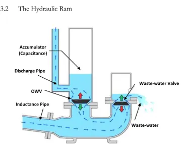
The Hydraulic Ram
The hydraulic (or water) ram has been used as a means of elevating water for an age, with some early accounts of force pumps using an air cavity dating as far back as 300 B.C by the Greeks [88]. Even the first recorded design of a hydraulic ram was
Accumulator (Capacitance)
Discharge Pipe
OWV
Inductance Pipe
Waste-water Valve
[image:62.595.113.489.288.583.2]Waste-water
45 coined by Whitehurst in 1775 [89] with the more modern automated version following shortly after with Montgolfier’s pump [90]. Since then, the more widely accepted version of the pumps design has been implemented and its operation studied and improved [88, 91-93], with the pump being used throughout the 20th century mainly to supply farmland or to power water features on large estates. More recently, the hydraulic ram is being seen as a good option for rural water pumping for its simplicity, low cost and sustainability [16, 94, 95]. The hydraulic ram, much like the induced flow pumps mentioned previously, relies on the inertia of a fluid in motion for its components to function together. Its operation is now examined.
46 Burton and Short’s induced flow pump the positioning of the inductance and capacitance allows for the decoupling of pumping head and input flow.
Due to the nature of their operation being fully reliant on a readily available water source, which may be used to provide a continuous flow through the inductance pipe, hydraulic rams have limitations to their use. Not least is the limitation to mainly hilly areas with all year round water supplies, making them unsuitable for many rural areas [16]. Further, as a large amount of the water used to provide the lift through the pump is lost from the waste-water valve, the scale of pumping is limited.
3.3
Electric-Hydraulic Analogy
The electric-hydraulic analogy (or sometimes hydraulic analogy) may be used to relate equations defining the transport of fluid through a system to the flow of current through a DC electrical circuit. In this way, there may be several comparisons drawn between the operating characteristics of both systems, namely: Voltage-Pressure, Flow-Current and ground reservoir-earth relationships [96]. This analogy has previously been used by Short in his definition of the induced flow reciprocating pump [64]. In the following sections, the boost-converter from DC power electronics is compared to the hydraulic ram and a simple equivalent design produced for a centrifugal pumping system.
3.3.1
The DC-DC Boost-Converter
47
Input Vi
Inductance, L Diode, D
Load, R
Output, Vo Switch,
S
Capacitance, C
primary example of this is electric or hybrid car batteries. Figure 3-3 provides an illustration for a simple boost-converter:
This design may be seen to be analogous to the hydraulic ram system illustrated by Figure 3-2. Both make use of an inductance, capacitance, one-way valve to regulate flow ‘upstream’ to the system output, and a release valve to ensure an increase in flow through the inductance periodically between system discharges. The only main difference between the two systems is that with the boost-converter, the switch, or ‘waste-valve’, is electronically controlled and based on a system duty (dependent on the operating conditions and resonant parameters of the circuit).
3.3.2
Centrifugal Water Pump with Pressure Boost
Making use of the electric-hydraulic analogy and recalling that an MPPT may be used to decouple a PV panels output from its operating conditions, it is possible to replace the electrical components in the boost-converter circuit with hydraulic components to form a pressure-boost circuit. In this case, the input voltage is replaced by a constant system pressure (created by a centrifugal pump), much like the constant flow source in a hydraulic ram. In the same way an MPPT applies the correct resistance
48
Centrifugal Pump Input,
QL1
Inductance, L1
ECV
OWV
Discharge Pipe
Fluid Softness (Capacitance), K
Load, POut
Output, QD
Fluid Reservoir Discharge Reservoir
or load to the electrical PV circuit (ensuring maximum power is drawn from the panel), the equivalent hydraulic circuit would correct the load on the pump to ensure maximum hydraulic power. More detail on the design of such a system is presented in
Chapter 4. The basic layout is presented in Figure 3-4.
Similar hydraulic circuits have been suggested as a means of pressure boosting in mechatronics and fluid power control systems [97-101]. Although such articles highlight the benefits of high speed valves as a means of hydraulic pressure-boost and suitability of the application of such circuits for use with centrifugal pumps, the theory has not yet been applied to water pumping systems with the main focus being discharge flow and maintenance of BEP conditions for the centrifugal pump.
3.4
Summary and Conclusions
The principles and advantages of an induced flow system in reciprocating pumps have been identified, illustrating how the operational range of a pump may be expanded to make such pumps more applicable to lower heads. Further, from the
49 comparison of this system to a traditional hydraulic ram, similarities have been drawn to boost-converters as a means of pressure boosting in hydraulic circuits.
![Fig. 3-1 – A simple hand pump version of the joggle tube [85]](https://thumb-us.123doks.com/thumbv2/123dok_us/8066512.226776/60.595.200.367.271.489/fig-simple-hand-pump-version-joggle-tube.webp)