12
thICSGE
10-12 Dec. 2007 Cairo - Egypt
Ain Shams University
Faculty of Engineering
Department of Structural Engineering
Twelfth International Colloquium on Structural and Geotechnical Engineering
EFFECT OF AXIAL COMPRESSION STRESS ON THE SHEAR BEHAVIOR
OF HIGH-STRENGTH FIBER REINFORCED CONCRETE T-BEAMS
OMAR A. ABD ELALIM M.Sc. candidate, Ain Shams University
AHMED H. GHALLAB
Associate Professor, Department of Structural Engineering, Ain Shams University E-mail:ahghallab@yahoo.co.uk
IBRAHIM G. SHABAAN
Professor of concrete structures, Department of Structural Engineering, Banha University OMAR A. ELNAWAWY
Professor of concrete structures, Department of Structural Engineering, Ain Shams University E-mail:nawawyomar@hotmail.com
ABSTRACT
The effect of axial compression stress on the shear behaviour of High-strength Steel Fibre Reinforced Concrete T-beams was experimentally evaluated in this study. The main studied factors were the volume ratio of the steel fibre, the stirrups ratio and the flange width of the T-beam section. All beams were over-designed in flexure to ensure shear failure. The studied beams were tested under two third point loads. The results showed that applying axial compression stresses were effective in reducing the cracks widths and cracks propagation. Test results show the improvement in the stiffness, cracking and ultimate strengths by adding fibre to beams without stirrups while in case of presence of stirrups, the effect of increasing the fibre volume ratio to 2%, was less than that of 1%. Also, it was found that the effect of adding stirrups on the beam properties decreases as the fibre volume ratio in the beam increases. Increasing the flange width did not affect the shear behaviour of the studied beams.
KEYWORDS
High-strength concrete, Fibre, Steel fibre, Stirrups, Shear behaviour.
1 INTRODUCTION
To improve the shear capacity of the concrete beam, several methods can be used. One of these methods is the addition of steel fibres to the concrete mix. Steel fibres not only improves the shear strength of the concrete beam but also enhance it flexural behaviour
Shear tests on steel fiber reinforced concrete (SFRC) beams without stirrups have shown that if the fiber dosage is high enough no other transverse reinforcement is necessary to achieve the desired shear capacity. Furthermore SFRC beams show a more ductile behavior and have reduced crack widths compared to beams without fibres [8-13].
The behaviour of SFRC beams was extensively examined in shear and flexure. However, most of previous studies were conducted using an independent test specimens without restraints. Although, reinforced concrete beams in real concrete structures are members in a frame structure and they behave differently from such idealized members because of the axial restraint imposed by adjacent members. From a previous studies [15,18-20], it was found that the flexural and shear behaviour characteristics and the failure modes of reinforced concrete flexural members are governed by the intensity of axial restraints.
2 OBJECTIVE AND SCOPE
In this paper, eight High Strength Fibre Reinforced Concrete (HSFRC) T-beams with the same tensile and compressive reinforcement and subject to the same axial compressive stress were tested. All tested beams were over reinforced in flexure to ensure shear failure. Besides the effect of the compressive stress, the effect of Fiber content, vertical stirrups ratio and the effective flange width were studied. A single reference beam specimen had neither vertical stirrups nor fibres and did not subject to axial compressive stress was also tested. Test results including cracking behaviour, cracking strength and ultimate strength were studied to assess the effect of axial compressive restrain stress on the shear behaviour of tested beams with varying fiber content, vertical stirrups ratio and effective flange width.
3 EXPERIMENTAL PROGRAM
3.1 Materials
The tested RC beams were casted from ordinary Portland cement, natural sand and crushed dolomite with a maximum size of 15 mm. Silica fume and superplastisizer were added to the mix to increase strength and to have an acceptable workability. Hooked-End Steel fibers of constant aspect ratio (Lf / Df = 50 mm /1 mm = 50) were used in this
study. The selection of Hooked-End steel fibres was based on the results of previous research that showed its superiority over the corrugated steel fibres [3].
3.2 Concrete Mixes
[image:2.595.106.543.701.780.2]The concrete mix proportions were chosen based on the results of several trial mixes carried out to obtain the required compressive strength and a reasonable workability. To achieve this a superplasticizer and silica fume were added to the mix. Mix proportions for the concrete mix used in this study are shown in Table l.
Table 1 Mix proportions for studied beams
Target concrete Strength, (MPa)
Proportions, Kg/m3
Cement Sand Dolomite Silica
Fume Water
Super Plasticizer
Lit/m3
3.3 Mixing and preparation of tested beams
The dry coarse aggregate, cement and sand were first mixed for about one minute before adding half of the mixing water. After two minutes of mixing, the remaining mixing water and superplastisizer were added. The fibres were added slowly to the running mixer, after three minutes, to avoid clumping. Then concrete was casted in the moulds and demolded after 24 hours from casting, covered with wet burlap, and stored under laboratory conditions for 28 days. In addition, three 150-mm cubes were casted from each beam mix and tested for compressive strength after a water-curing period of 7&28 days. The mean compressive strength of concrete at 28 days is tabulated in Table 2.
3.4 Details of tested beams
The experimental program consisted of testing nine T-sec HSFRC beams. Dimensions of the tested beams are shown in Figure (1) while the properties of the beams are shown in table 2. All beams had a span length equals to 1.7 m and effective span of 1.50 m and were reinforced with 4Ø16 (fy=360 MPa) as bottom longitudinal reinforcement to prevent flexural failure and 2Ø12 (fy=360MPa) as top reinforcement.
Table 2: Properties and test results of the tested beams
Beam No.
Fcu
(Mpa)
Fiber Content
(Vf %)
Axial compressive
stress fa
(MPa)
Stirrups ratio (ρs%)
Flange Width (mm)
Pcr, (kN)
Pult, (kN)
Failure Mode
B1 96 0 0 0 300 49 78 Shear
B2 100 0 13.5 0 300 66 97 Shear
B3 85 1 13.5 0 300 94 149
Shear-Compression
B4 90 2 13.5 0 300 101 162
Tension-shear
B5 87 0 13.5 0.45 300 75 119 Shear
B6 88 1 13.5 0.45 300 100 159
Shear-Compression
B7 92 2 13.5 0.45 300 87 159
Tension-shear
B9 100 1 13.5 0.45 400 96 167 Shear
B10 96 1 13.5 0.79 400 100 177 Shear
3.5 Instrumentation and Testing Procedure
Sec A-A
Sec B-B
4 TEST RESULTS
[image:5.595.92.512.558.704.2]Tested beams were divided to five groups based on the studied factors as shown in Table (3). The experiment results of tests are shown in table (2). Following the effect of each studied factor on the behaviour of the tested beams is discussed and compared.
Table 3:Factors and groups numbers
Group
no.* Factors Beams No.
G1 Value of axial compressive
stresses (fa) (0 & 13.5) MPa B1 & B2
G2
Steel fiber volume ratio (Vf)
(Without Web RFT) B2, B3 & B4
G3 (With Web RFT) B5, B6 & B7
G4
Web RFT. (ρst)
(Vf = 0) B2 & B5
G5 (Vf = 1%) B3 & B6
G6 (Vf = 2%) B4 & B7
G7 (Vf = 1%) ,(B=400mm) B9 & B10
G8 Flange Width (B) (Without Web RFT) B6 & B9 *All beams (except beam B1) were subjected to axial compressive stress equals to 0.15 MPa
4.1 Effect of Axial Compression stress (fa)
Two beams ;Beam B1 (fa=0) and beam B2(fa=13.5 MPa), were tested to study the effect of axial compression stress on the behaviour of the high-strength T-beams. During loading, number of flexural cracks on beam B1 was higher than that on beam B2 and extended vertically up to bottom of the flange while those on beam B2 had not reached the mid height of the web as shown in Fig. (2). This also was observed on the shear span where the shear cracks on beam B1 extended higher than those on beam B2 but the shear cracks were steeper in case of beam B2. The difference between the cracking patterns of the two beams can be attributed to the effect of the compressive axial stresses that reduced the load tensile stresses and prevented the extension of the cracks. Also, the steeper angle of shear cracks on beam B2 show the effectiveness of vertical stirrups in the presence of axial compressive stress; as higher number of vertical stirrups will intersect the diagonal crack.
Fig.2: Cracking pattern for beams B1 and B2
those on beam B1 that lead to improve its stiffness even in the uncracked stage as shown in Fig. (3). This was accompanied by a reduction in its deflection compared with that of beam B1. This agrees with the observations and conclusions of Yang et. al. [18].
Fig (3): Effect of axial compression stress on load-deflection curves of SFRHSC beams without stirrups
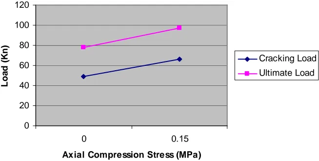
Also, the presence of axial compression stress resulted in improving both the cracking and the ultimate strengths; the first cracking load and ultimate load of beam B2 were higher than those of beam B1 by 61% and 25% respectively as shown in Table (2). However, the improvement in the cracking strength was significantly higher than the improvement in the ultimate strength.
Fig (4): Effect of axial compression stress on Cracking and ultimate loads
4.2 Effect of Fibre Content
The effect of fibre content was studied in two cases; the first was in case of absence of stirrups while the second case was in presence of stirrups.
4.2.1 Beams without stirrups
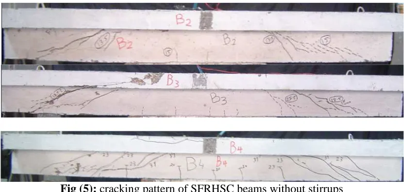
In the first case three T-beams (B2, B3 and B4) were tested. The ratio of volume of fibre was 0, 1% and 2% respectively. during loading, the number of flexural and shear cracks increased and cracks extended as the ratio of fibre volume (Vf) increased as shown in
Fig. (5) 0 50 100 150 200 250 300 350
0 5 10 15 20 25 30
Deflection (mm)
Beam 1 Beam 2
0 20 40 60 80 100 120
0 0.15
Axial Compression Stress (MPa)
L
o
a
d
(
K
n
)
Cracking Load
[image:6.595.120.494.117.310.2] [image:6.595.142.469.434.599.2]
Fig (5): cracking pattern of SFRHSC beams without stirrups
By increasing the fibre volume ratio, the cracking shear strength seems to be increased as shown in Fig. (6). This can be attributed to the increase in number of fibers that intersect the cracks and incorporated in resisting the shear stress as the Vf increases.
After cracking, the shear stresses in tested T-beams without stirrups and without fibres, is resisted by the compression zone of concrete, aggregate interlock and the dowel action of the longitudinal reinforcement. As the load increased, the crack width increased and the aggregate interlock reduced resulting in loss of the total strength. In beams without stirrups but with fibres, the fibres hold the crack faces together and prevented or reduced the loss in the aggregate interlock. Also, the fibres helped to redistribute the stresses between the cracked and uncracked regions, hence, reduced the steel stress and delayed the debonding between fibers and concrete. Thus, it improved the ultimate shear strength of the tested beam (compared to the control RC beams).
The improvement in both the cracking and ultimate shear capacities enabled the beam to carry higher load that resulted in increasing and extending of both the flexural and shear cracks.
By studying the load deflection curves of beam B2(without fibre), beam B3 (Vf = 1%)
and beam B4 (Vf = 2%), it could be seen that the stiffness of the two beams B3 & B4
[image:7.595.96.512.65.263.2]Fig (6): load-deflection curves of SFRHSC beams without stirrups
Adding 1% of fibres to the beam B3 led to increase both of the first crack load and ultimate load by 42% and 53% respectively compared with those of beam B2 (without fibres). Also, increasing the volume percentage of fibres to 2% for beam B4 resulted in increasing the first crack load by 53% and the ultimate load increased by 67% over those of beam B2 (without fibres).
Fig (7): Effect of fibre content on Cracking and ultimate loads
All tested beams were over-reinforced in flexure and compression to ensure shear failure. However, the presence of fibre (with Vf =1%) in beam B3 changed the failure
mode from shear failure of beam B2 to compression shear failure of beam B3 and by increasing the fibre volume ratio to 2% (in beam B4), the failure was changed to tension-shear failure. This is due to the contribution of fibres in resisting loads and hence improving the beam shear capacity.
4.3 Effect of Stirrups
The effect of stirrups on the behaviour of HSC beams subjected to compressive stresses was studied by comparing test results of beams B2,B3,B4,B5,B6 and B7. For all the studied cases, it was found that when adding stirrups to the tested beams, the length of the flexural cracks were increased. This shows that the presence of transverse reinforcement resulted in propagation of flexural cracks. For the diagonal cracks, it was
0 50 100 150 200 250 300 350
0 5 10 15 20 25 30
Deflection (mm)
L
o
a
d
(
K
N
)
Beam 2 Beam 3 Beam 4
0 20 40 60 80 100 120 140 160 180
0 1 2
Fibre Content, (%)
L
o
a
d
(
K
n
)
Cracking Load
[image:8.595.96.515.57.261.2] [image:8.595.108.501.374.560.2]found that for beam without stirrups, there was only a major single diagonal crack on one end of the beams extending throughout the shear span but when adding stirrups, the number of diagonal cracks increased. This is due to the redistribution of stresses due to the presence of web RFT. Fig. 8 shows the cracking patterns of both beam B4 (No web RFT) and beam B7 (with web RFT) as an example to show the effect of web RFT on the cracking patterns of the tested beams.
Fig (8): Cracking patterns of SFRHSC beams with fibre content (2%)
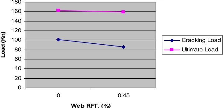
The effect of stirrups on the cracking and ultimate capacities of the tested beams was varied with the fibre volume ratio value as shown from Fig. 9, 11 and 13. Adding stirrups to tested beam without fibres (B5) increased its cracking load and ultimate capacity compared to those of beam B2 by 9.5% and 22%, respectively. While adding web RFT to beam with fibre volume ratio of 1% (B6) increased its cracking load and ultimate capacity, compared to beam B3, by about the same ratio (6%). For beams with fibre volume ratio of 2%, adding stirrups decreased the cracking and ultimate capacities of B7 than that of B4 by about 14 and 1.9% respectively.
Fig (9): relation between load and deflection and effect of web rft on the cracking and
ultimate load of beams without fibres
0 20 40 60 80 100 120
0 5 10 15 20 25
Deflection (mm)
L
o
a
d
(
K
n
)
[image:9.595.93.508.156.296.2] [image:9.595.95.472.437.617.2]Fig (10): Effect of web rft on Cracking and ultimate loads of beams without fibres
Fig (11): Relation between load and deflection and effect of web rft on the cracking and
ultimate load of beams with 1% fibres
Fig (12): Effect of web rft on Cracking and ultimate loads of beams with 1% fibres
0 20 40 60 80 100 120 140 0 0.45
Web RFT, (%)
L o a d ( K n ) Cracking Load Ultimate Load 0 20 40 60 80 100 120 140 160 180
0 5 10 15 20 25
Deflection (mm) L o a d ( K N ) Beam 3 Beam 6 0 20 40 60 80 100 120 140 160 180 0 0.45
Web RFT, (%)
[image:10.595.115.494.59.232.2] [image:10.595.122.481.487.675.2]Fig (13): Relation between load and deflection and effect of web rft on the cracking and
ultimate load for beams with 2% fibres
Fig (14): Effect of web rft on Cracking and ultimate loads of beams with 2% fibres
4.4 Effect of Flange Width (B)
Increasing the flange width didn’t show any improvement in the shear behavior of the tested beams. The cracking patterns for the two beams B6 (B=300mm) and B9 (B=400mm) were almost typical and both the flexural and shear cracks appeared on both beams at almost the same load ; 200 Kn, as shown in fig. (17). Also the stiffness of the beam was not clearly affected by the increase in the flange width.
Fig (15): cracking pattern of SFRHSC beams B6 and B9
0 20 40 60 80 100 120 140 160 180
0 5 10 15 20 25
Deflection (mm)
L
o
a
d
(
K
N
)
Beam 4 Beam 7
0 20 40 60 80 100 120 140 160 180
0 0.45
We b RFT, (%)
L
o
a
d
(
K
n
)
Cracking Load
[image:11.595.96.492.54.254.2] [image:11.595.122.480.303.476.2]Only a slight improvement was shown in the cracking and the ultimate loads as it was found that the cracking load of B9 was less than that of beam B6 by about 4% while its ultimate capacity was increased than that of beam B6 by about 5% respectively.
Fig (16): relation between load and deflection and effect of web rft on the cracking and ultimate load for beams B6 and B9
Fig (17): relation between load and deflection and effect of web rft on the cracking and ultimate load for beams B6 and B9
5 CONCLUSIONS
In this study the shear behavior of high-strength fiber reinforced concrete T-beams subjected to axial compression stresses has been investigated experimentally. The main variables in this study were fibre volume ratio, stirrups ratio and flange width. All beams were tested under two third points loading. Based on the experimental results the following conclusions were drawn:
1 Applying axial compression stresses to the tested beams led to improvement in the concrete cracking and ultimate shear loads.
2 In case of beams without stirrups, as the fibre volume ratio in the concrete increases the shear capacity of the beams improves.
3 For tested beams with stirrups, adding fibres to the concrete increases the shear capacity of the beams but this phenomenon is satisfied until reaching certain volume content. This volume content is the optimum value for adding fibres to concrete. Increasing the fibre content for beams with web RFT than this percentage may cause a negative effect on concrete instead of improving it.
4 Effect of stirrups was studied in different cases. It was studied without the presence of fibres and in the presence of different fibre volume ratio. By
0 20 40 60 80 100 120 140 160 180
0 5 10 15 20 25
Deflection (mm) L o a d ( K N ) Beam 6 Beam 9 0 20 40 60 80 100 120 140 160 180 300 400
Flange Width, (mm)
[image:12.595.142.474.101.256.2] [image:12.595.103.461.293.469.2]studying these cases, it was found that the effect of adding stirrups on the cracking and the ultimate strength decreases as the fibre volume ratio increases in the beams. It was found that the effect of adding web RFT was efficient when there was no fibres and when adding fibres of 1% its effect began to decrease and at fibre content of 2% it became almost insignificant.
5 Increasing the flange width in the tested T-beams doesn’t affect the shear capacity of concrete section, although it improves the flexure behaviour of the beam.
6 REFERENCES
[1] El-Zanaty, A., Nilson, A., and Slate, F., “Shear-critical high-strength concrete beams”, Report 85-1, Department of Structural Engineering, Comet University, Ithaca, New York, 1985, pp.216.
[2] Gabrielson, H., “High performance concrete beams tested in shear. Comparison between the traditional approach and the modified compression field theory”, Proceedings of the international symposium on utilization of high-strength concrete, Lillehammer, Norway, 20-23 June 1993, pp 169-176.
[3] Kim, ,L, Park, Y., and Lee, S., “Shear strength of reinforced high-strength concrete beams”, Proceedings of the international symposium on utilization of high-strength concrete, Lillehammer, Norway, 20-23 June 1993, pp 251-258.
[4] Mphonde, A., end Frantz, G., “Shear tests of high and low strength concrete beams without stirrups”, ACI Journal, Proceedings Vol. 81(4), July-August 1984, pp 350-357.
[5] Remmcl,G. ,and Konig,G., “The tensile behavior of high-strength concrete and its effect on the shear strength of longitudinally reinforced concrete members”, Proceedings of the international symposium on utilization of high-strength concrete, Lillehammer, Norway, 20-23 June 1993, pp 269-276.
[6] Shuaib, A., Khaloo, A., and Poveda, A.,” Shear capacity of reinforced high-strength concrete beams”, ACI journal, Proceedings Vol. 83(2), March-April 1986, pp 297-305.
[7] Chung, W., “Analytical model for diagonal tension failure of reinforced concrete members under static load, PhD thesis”, North Carolina State University, May 1992, pp141.
[8] Imam, M., Vandewalle, L., Mortelmans, F., “Shear-moment analysis of reinforced high-strength concrete beams containing steel fibres”, Canadian Journal of Civil Engineering, Vol. 22, 1995, pp 462-470.
[9] Ashour, S., Hasanain, G., and Wafa, F., “Shear behavior of high-strength fiber reinforced concrete beams”, ACI Structural Journal, Proceedings Vol. 89 (2), March-April 1992, pp 176-184
[10] Shin, S., Oh, J., and Ghosh, S, “Shear behavior of laboratory sized high-strength concrete beams reinforced with bars and steel fibers”, ACI, SP 142, Fiber reinforced concrete developments and innovations, 1994, pp 181-200
[11] Narayan, R., Darwish, Y., “Use of steel fibers as shear reinforcement”, ACI Structural Journal, May-June 1987, pp 216-227.
[13] ACI 544.4R-88 (reapproved 1999), Design considerations for steel fiber reinforced concrete. American Concrete Institute, Farmington Hills, Michigan, 1999, pp.18.
[14] State-of-the-Art “Report on high-strength Concrete”, ACI 363R-92, ACI Committee 363 Report, American Concrete Institute, Detroit, 1992.
[15] I.Shaaban, "Shear behaviour of high-strength fibre reinforced concrete beams subjected to axial compression forces", Ain Shams Scientific Bulletin 2004, Vol 39, No. 4, pp.91-117., Egypt.
[16] Farahat, A.M. “Effectiveness of steel fibres on the shear resistance of high-strength reinforced concrete beams” Engineering Research Journal, Helwan University, Vol. 91, Feb.2003, pp.35-55.
[17] ACI Committee 318, "Building code requirements for structural concrete and commentary (ACI 318-02) American Concrete Institute, Mich., 2002.
[18] Yang, E. I., Yi, S. T., and Morita, S., "Effect of axial restraint on flexural and shear behaviour of high-strength concrete members". Magazine of Concrete Research, Vol. 56, No. 2, March, 2004, pp. 63-72.
[19] EI-Dodo, G. E., "Effect of axial force on shear strength of reinforced concrete elements". Cairo University, Ph.D. Thesis, 1992, Cairo University, Egypt.
[20] Abdoun, S. G., "Effect of axial compressive stresses on shear strength of high-strength concrete beams with web reinforcement ", Ph.D. Thesis, 1998, Cairo University, Egypt.