Proceedings of the
EASTERN JOINT COMPUTER CONFERENCE
December
1-3, 1959
Boston, Massachusetts
Sponsors:
THE INSTITUTE OF RADIO ENGINEERS
Professional Group on Electronic ComputersTHE AMERICAN INSTITUTE OF ELECTRICAL ENGINEERS
Committee on Computing DevicesTHE ASSOCIATION FOR COMPUTING MACHINERY
Printed in the United States of America
No.
16
ADDITIONAL COPIES
Additional copies may be purchased from the following sponsor-ing societies at $3.00 per copy. Checks should be made payable to anyone of the following societies:
INSTITUTE OF RADIO ENGINEERS 1 East 79th Street, New York 21, N. Y.
AMERICAN INSTITUTE OF ELECTRICAL ENGINEERS 33 West 39th Street, New York 18, N. Y.
ASSOCIATION FOR COMPUTING MACHINERY 2 East 63rd Street, New York 21, N. Y.
COPIES OF PRIOR PUBLICATIONS
Copies of publications issued in connection with the prior Joint Computer Conferences listed below may also be purchased from the above societies.
NUMBER CONFERENCE LOCATION DATE
1 Eastern Philadelphia Dec. 10-12, 1951 2 Eastern New York City Dec. 10-12, 1952
3 Western Los Angeles Feb. 4-6,1953
4 Eastern Washington Dec. 8-10, 1953
5 Western Los Angeles Feb. 11-12, 1954 6 Eastern Philadelphia Dec. 8-10, 1954
7 Western Los Angeles Mar. 1-3,1955
8 Eastern Boston Nov. 7 -9, 1955
9 Western San Francisco Feb. 7 -9, 1956 10 Eastern New York City Dec. 10-12, 1956 11 Western Los Angeles Feb. 26-28, 1957 12 Eastern Washington Dec. 9-13, 1957
13 Western Los Angeles May 6 -8,1958
14 Eastern Philadelphia Dec. 3 -5,1958
15 Western San Francisco Mar. 3 -- 5, 1959
Copyright © 1959
PROCEEDINGS OF THE
EASTERN 'JOINT COMPUTER CONFERENCE
PAPERS PRESENTED AT
THE JOINT IRE-AIEE-ACM COMPUTER CONFERENCE
BOSTON, MASSACHUSETTS, DECEMBER
1-3, 1959Sponsors
THE INSTITUTE OF RADIO ENGINEERS
ProFessional Group on Electronic Computers
THE AMERICAN INSTITUTE OF ELECTRICAL ENGINEERS
Committee on Computing Devices
THE ASSOCIATION FOR COMPUTING MACHINERY
Published by
THE
1959EASTERN JOINT COMPUTER CONFERENCE
FOR
THE NATIONAL JOINT COMPUTER COMMITTEE
2 195,9 PROCEEDINGS OF THE EASTERN JOINT COMPUTER CONFERENCE
NATIONAL JOINT COMPUTER COMMITTEE
Chairman Vjce-Chairman
Harry H. Goode Paul Armer
Department of Electrical Engineering University of Michigan
The RAND Corporation Santa Monica, California Ann Arbor, Michigan
IRE Representatives Werner Buchholz
Product Development Laboratory IBM Corporation
Poughkeepsie, New York R. D. Elbourn
National Bureau of Standards Department of Commerce Washington, D. C. Harry H. Goode
Secretary-T~easurer
Margaret R. Fox
National Bureau of Standards Department of Commerce Washington, D. C.
AlEE Representatives R. R. Johnson
Computer La.boratory General Electric Company Phoenix, Arizona
Claude A. R. Kagan Engineering Research Center Western Electric Company, Inc. Princeton, New Jersey
Stanley Rogers Department of Electrical Engineering
University of Michigan
Convair Division
General Dynamics Corporation San Diego, California
Ann Arbor, Michigan Willis H. Ware
The RAND Corporation Santa Monica. California
Paul Armer
The RAND Corporation Santa Monica. California H. R. J. Grosch
Morris Rubinoff
Moore School of Engineering University of Pennsylvania Philadelphia, Pennsylvania
ACM Representatives
J. D. Madden
System Development Corporation Santa Monica, California F. M. Verzuh
Corporation for Economic & Industrial Research Los Angeles, California
Massachusetts Institute of Technology Cambridge, Massachusetts
R. W. Hamming (ACM) Bell Telephone Laboratories Murray Hill, New Jersey
Jack Moshman CACM)
Ex-Officio Representatives
Richard O. Endres (IRE) Rese Engineering, Incorporated Philadelphia, Pennsylvania Reuben A. Imm (AlEE)
IBM Corporation Rochester, Minnesota
Headquarters Representatives L. G. Cumming Corporation for Economic & Industrial Research
Arlington, Virginia
The Institute of Radio Engineers New York. New York
R. S. Gardner
American Institute of Electrical Engineers 33 West 39th Street
1959 PROCEEDINGS OF THE EASTERN JOINT COMPUTER CONFERENCE 3
TABLE OF CONTENTS
Page Foreword ... Frank E. Heart, Conference Chairman 5 Award for the Best Presentation of a Technical Paper. . . 7 Computers of the Future ... Rex Rice 8 Negative-Resistance Elements as Digital Computer Components .. , ... Morton H. Lewin 15 Deposited Magnetic Films as Logic Elements ... " ... . A. Franck, G. F. Marette and B. I. Parsegyan 28 Solid-State Microwave High Speed Computers ... Jan A. Rajchman 38 The Engineering Design of the Stretch Computer. . . .. . ... Erich Bloch 48 Design of Univac-LARC System: I. .. ... . ... J. P. Eckert, J. C. Chu, A. B.o Tonik and W. F. Schmitt 59 Design of Univac-LARC System: II ... H. Lukojf, L. M. Spandorfer and F. F. Lee 66 Arithmetic and Control Techniques in a Multiprogram Computer ... " .. . N. Lourie, H. Schrimpf, R. Reach and W. Kahn 75 The Virtual Memory in the STRETCH Computer ... J. Cocke and H. G. Kolsky 82 A Combined Analog-Digital Differential Analyzer ... Harold K. Skramstad 94 The System Organization of MOBIDIC B ... Stanley K. Chao 101 A Universal Computer Capable of Executing an Arbitrary Number of Sub-Programs Simultaneously ... John Holland 108 The Multi-Sequence Computer as a Communications Tool. ... " ... " ... J. N. Ackley 114 Realization of Boolean Polynomials Based on Incidence Matrices ... . S. Okada, Y. Moriwaki and K. P. Young 120 Applications of Boolean Matrices to the Analysis of Flow Diagrams ... Reese T. Prosser 133 SIMCOM - The Simulator Compiler ... Thomas G. Sanborn 139 Unusual Techniques Employed in Heat Transfer Programs ... . D. J. Campbell and Mrs. D. B. Vollenweider 143 The Automatic Transcription of Machine Shorthand ... Gerard Salton 148 Critical-Path Planning and Scheduling ... . J. E. Kelley, Jr., and M. R. Walker 160 The Automatic Digital Computer as an Aid in Medical Diagnosis ... . C. B. Crumb, Jr., and C. E. Rupe, M.D. 174 An Advanced Magnetic Tape System for Data Processing ... Richard B. Lawrance 181 A High Speed, Small Size Magnetic Drum Memory Unit
for Subminiature Digital Computers ... . M. May, G. P. Miller, R. A. Howard and G. A. Shifrin 190 Temperature Compensation for a Core Memory. . . . .. . A. H. Ashley, E. U. Cohler and W. S. Humphrey, Jr. 200 Use of a Computer to Design Character Recognition Logic ... , ... R. J. Evey 205 A Self-Organizing Binary System ... Richard L. Mattson 212 Alpha-Numeric Character Recognition Using Local Operations ... J. S. Bomba 218 Pattern Recognition and Reading by Machine ... W. W. Bledsoe and I. Browning 225
Discussion of Problems in Pattern Recognition ... , .. 233
4 1959 PROCEEDINGS OF THE EASTERN JOINT. COMPUTER CONFERENCE
EASTERN JOINT COMPUTER CONFERENCE COMMITTEE
Chairman. . . Frank E. Heart, MIT Lincoln Laboratory
Program Committee ... . Jean H. Felker, Chairman, Bell Telephone Laboratories
Robert A. Kudlich, Vice Chairman, AC Spark Plug Division
Mandalay Grems, IBM Corporation
Ben M. Gurley, Digital Equipment Corporation John W. Haanstra, IBM Corporation
Marvin Jacoby, Sperry Rand Corporation W. J. Poppelbaum, rniversity of Illinois
Publications . . Harlan E. Anderson, Chairman, Digital Equipment Corporation John L. Atwood, Digital Equipment Corporation
Richard L. Best, Digital Equipment Corporation William Hosier, Sylvania Electric Products, Inc. Lawrence R. Jeffery, The MITRE Corporation
Local Arrangements. . Harrison \V. Fuller, Chairman, Laboratory for Electronics
Philip R. Bagley, Yice Chairman, The MITRE Corporation Finance David L. Bailey, The MITRE Corporation
Henry E. Frachtman, The MITRE Corporation Hotel '. . . S. Paul Blumenthal, Laboratory for Electronics Alfred E. Ventola, Jr., Laboratory for Electronics Publicity and Printing. Douglas T. Ross, Massachusetts Institute of Technology
George D. Wood, Jr., Massachusetts Institute of Technology Robert Kramer, Massachusetts Institute of Technology Registration. . . . . Robert Pearson, Laboratory for Electronics
Henry L. Schmitz, Jr., IBM Corporation Trips .. Rollin P. Mayer, The MITRE Corporation
Alexander Vanderburgh, MIT Lincoln Laboratory Hospitality. Arthur D. Hughes, The National Company
1959 PROCEEDINGS OF THE EASTERN JOINT COMPUTER CONFERENCE 5
Foreword
For some time it has been customary to hear com-plaints about the limited value of large technical conferences. Despite this fact, I represent a group of people who have worked assiduously to arrange this affair. And over 2,300 people have expended consider-able effort to attend. It is interesting to inquire seriously as to the reason for so much effort. There are, of course, a number of very cynical answers. However, I would like to offer a less cynical one.
Perhaps it is only a convenient rationalization1 but I still find the computer field an exciting and stimu-lating domain. The excitement about the computer arises in much the same way as the excitement about atomic energy; one may almost feel the changes being produced in society. For an applied scientist or engi-neer, it is usually the applications which lend to a discipline an aura of excitement. Well, then, I believe that many of us are here because of a continued en-thusiasm in the possibilities of the computer. The number and importance of the potential applications are still increasing more rapidly than the onset of general boredom.
In the tiny span of years from the first to the ninth EJCC, we have been witness to a wholesale change in the techniques of scientific computation, witness to a revolution in business data handling, and witness to the use of computers for real time control of weapons systems, industrial plants and space vehicles. Surely these events are exciting enough to partially justify our large conferences.
And yet I believe that the most important applica-tions of the computer have not yet been realized. Certainly computer inroads in the business world and the industrial plant have only just begun. However, for me, the most exciting applications are those which th~eaten to affect all aspects of human progress. I would like to point toward two such potentially pervasive applications - two impending applications that excite me considerably.
The first is the application of the computer in studying and copying the characteristics of biological systems. This is a doubly potent use of a computer, involving useful feedback, because real gains in understanding biological systems might lead to better computer systems. The first steps in this direction
have already been taken. Computers are being used for analysis of electroencephalograph data and will be used to study many other types of clinical data. Computers have been used to permit construction and study of models of neuron assemblages. A whole gamut of pattern recognition techniques is under-going intensive investigation. People are trying to learn about learning. (Actually, even if we don't get very far, we will have the harmless fun of construct-ing more and better maze-solvconstruct-ing programs and chess-playing programs while trying.)
The second application may be characterized as the library problem. I think that the proper way to measure the importance of this application is to think of it as a new way for people to tap the accu-mulated knowledge of the recent and distant past. .The printing press was one such new way to tap the experience of the past, but now there are difficulties. The large number of printed books and journals, the existence of important scientific communities sepa-rated by language barriers and the inadequacies of our present retrieval techniques have seriously restricted our ability to connect pertinent information to pertinent researchers.
The pace of scientific progress might well take a large jump if, upon receiving a new project, a re-searcher might receive a graded synthesis of all human experience on that subject from the local library computer. Similarly, a lawyer, faced with a new case, would surely like to receive a relevance-ordered listing of all applicable court experience, and a doctor might be willing to trade clinical data and careful reporting in return for ordered estimates of diagnosis. In its present form, the technical journal itself may be facing its last few decades. The library computer concept is quite powerful, and it may some day be expedient for an author to send a new tech-nical paper only to the library, without the continued expenditure of quite so much paper.
So, I don't think the excitement is dying out; I think it is increasing, and I expect that computer conferences will be of interest and value for some time to come.
FRANK E. HEART
6 1959 PROCEEDINGS OF THE EASTERN JOINT COMPUTER CONFERENCE
LIST OF EXHIBITORS
Aeronutronic Division, Ford Motor Company AMP, Inc.
Ampex Corporation AN elex Corporation
Autonetics Division, North American Aviation, Inc. Bel Air Industries, Inc.
Bendix Computer Division Benson-Lehner Corporation
Bryant Computer Products Division
Burroughs Corporation, ElectroData Division C-E-I-R, Inc.
C & K Components, Inc.
C. P. Clare & Company
Computer Control Company, Inc. Di/ An Controls, Inc.
Digital Equipment Corporation Digitronics Corporation
Elco Corporation
Electro-Measurements, Inc. Electronic Associates, Inc.
Engineered Electronics Company Fairchild Publications, Inc.
Fairchild Semiconductor Corporation Ferranti Electric, Inc..
General Ceramics Corporation
Gene.cal Electric Company, Light Military Elec-tronics Department
G P S Instrument Company Harford Metal Products, Inc. Harvey-Wells Electronics, Inc.
Instrument Specialties Company, Inc.
Intellectronics Laboratories, Ramo Wooldridge Divi-sion, Thompson Ramo Wooldridge, Inc.
International Business Machines Corporation Laboratory for Electronics, Inc.
Librascope, Inc.
Micro Switch Division, Minneapolis-Honeywell Reg-ulator Company
Minneapolis-Honeywell Regulator Company, DAT A-matic Division
Minnesota Mining and Manufacturing Company The National Cash Register Company
Packard Bell Computer Corporation George A. Philbrick Researches, Inc.
Philco Corporation, Government and Industrial Division
Potter Instrument Company, Inc. Radio Corporation of America Reeves Soundcraft Corporation
Remington Rand Univac Division, Sperry Rand Corporation
Rese Engineering, Inc. Royal McBee Corporation Sprague Electric Company
Stromberg-Carlson - San Diego
Sylvania Electronic Systems Division, Sylvania Electric Products, Inc.
Tally Register Corporation Telemeter Magnetics, Inc. Teletype Corporation
F. D. Thompson Publications, Inc.
Union Switch & Signal Division, Westinghouse Air
Brake Company Wang Laboratories, Inc.
Washington Aluminum Co., Inc.
1959 PROCEEDINGS OF THE EASTERN JOINT COMPUTER CONFERENCE 7
Award for the Best Presentation
of a Technical Paper
Dr. Harold K. Skramstad was born in Tacoma, Washington, in 1908. He received a B.S. de-gree from the College of Puget Sound and a Ph. D. in physics from the University of Washing-ton. He has been with the Na-tional Bureau of Standards since 1935 and is presently Assistant Chief for Systems, Data Proces-sing Systems Division.
He worked in the field of aero-dynamics until World War II, when he turned his efforts to guided missiles. He was a pioneer in this field, playing a key role in the development of the "BAT" missile. He was responsible for the development of one of the first flight simulator facilities. He is an Associate Fellow of the Institute of Aeronautical Science and a Senior Member of the In-stitute of Radio Engineers. He also served as a member of the Air Force "Advisory Board on Simulation," and he was first chairman of the Eastern Simula-tion Council.
In recognition of the fact that technical programs are sometimes marred by careless or obtuse pres-entation of papers, the Eastern Joint Computer Conference Committee decided to emphasize the importance of a good oral presentation by making an award of $;300 for the best presentation at the Conference of a paper describing significant work in the computer field.
Awarded to
DR. HAROLD
K.
SKRAMSTADNational Bureau of Standards Washington, D.C.
for his presentation of a paper entitled:
"A Combined Analog-Digital Differential
Analyzer"
An analog-digital differential analyzer has been designed which combines the analog advantages of high speed and continuous representation of variables with the digital capability of high preci-sion and dynamic range. I t is based on repre-senting dependent variables by two quantities, a digital number representing the more significant part and an electrical voltage representing the less significant part. As in the electronic analog computer, time is the independent variable.
8 1959 PROCEEDINGS OF THE EASTER}·l JOINT COMPUTER CONFERENCE
Computers of the Future
REX RICEt
INTRODUCTION
T
HIS PAPER considers the advances required inmany related technologies to revolutionize the construction and use of digital data processing systems. In the following discussion we are particu-larly concerned with the radical change in fabrication technology and wish to analyze the effect that this change will have on our methods of computer design and specification.
PRESENT METHODS
The manufacturing techniques used in the elec-tronic portion of today's digital data processing sys-tems are illustrated in Fig. 1. The active devices are
Fig. I-Present method.
standardized in these systems. Circuit standardization is established at what may be defined as the Boolean
function level. Circuits for AND, OR, Invert, Latch,
Trigger, etc., are standardized individually. The pluggable packaging usually combines several cir-cuits, either of the same type or in selected groups. A major system function such as a complete working storage register and all its controls, an arithmetic processing unit and its controls, etc., is obtained by assembling a group of circuit packages on a panel and interconnecting the circuit packages with individual wires. At the time the individual circuits and pack-ages are designed and optimized, very little
informa-tion is available regarding their specific employ~nt
in systems functions.
A digital "system function" may be defined as a
tIBM Research Laboratory, Poughkeepsie, N. Y.
combination of logical elements interconnected and timed to perform major operational sequences in a data processor. One of our future objectives is to create major digital system functions in one continu-ous, automated manufacturing sequence.
FUTURE METHODS
A possible future method for producing major sys-tem functions such as complete working storage registers, process units, memory arrays, etc., is illus-trated in Fig. 2. We envision this manufacturing line as a set of printing presses through which a conveyor system passes. Substrate material is placed on the conveyor and proceeds through the line. At each stage one pattern of interconnections, insulation, or active material is printed on the substrate. As re-quired, bake ovens, etc., may be strategically placed. Here, devices are standard by virtue of the materials used. These materials are applied by a standardized method to produce active elements, interconnections, insulation, etc., in batches. The plates, inserted in each press, are made in an automatic machine which develops the appropriate layout under equation con-trol for major system segments.
I~ (B I~ I~ I~
iJ
BULK MAT'L
Fig. 2-A future method.
Rice: Computers of the Future 9
Illustrative Example of a System Function
A serial-by-digit, decimal adder is used to illustrate a system function as shown in Fig. 3. This represents a portion of an arithmetic processing unit. The digital code assumed is a decimal "one out of ten" repre-sentation, chosen because decimal matrix addition is well understood. Other examples or codes would have served equally well.
B
INPUT
DRIVE FIRST HAlF ADO MATRIX
1
CONTROLS AND DELAY DECIMAL ADDITION - SERIAL BY DIGIT
1
SECOND HAlF ADD. O£CK A~ DRIVE
Fig. 3-Illustrative example of a system function.
In this function a pair of decimal digits enters a
process unit at A and B and the added result is
ob-tained at the output. A matrix, to be described in detail, performs the first half-addition. Other ele-ments provide input drive, output carry detection
recombination, and the second half addition. It
i~
also necessary to store the presence or absence of a carry, so that as succeeding pairs of digits are proc-essed, the second half-addition circuit may be
acti-vated. Let it be assumed by way of example that A
equals 5 and B equals 6, as emphasized with heavy
marked lines. In the matrix the 5 on the vertical axis together with a 6 on the horizontal axis activates an
AND circuit which places an output on the eleventh
diagonal. After passing through the carry detection element, the eleventh diagonal is recombined with the
~
II----__t"--_--.. OUT
--~
Fig. 4-Standard "and-inverter" circuit (TRL).
output line 1. The carry condition is remembered for
later use. Let us now consider circuits for the matrix' in more detail.
Matrix Utilizing Individual, Standardized Boolean Circuits
The circuit in Fig. 4 is a Boolean standardized
two-way AND circuit with one transistor, four resistors,
and various internal interconnections. Several out-puts may be wired together to form an appropriate
OR circuit. A two-way circuit is chosen, since for our
purposes in the addition matrix a three- or four-way
AND circuit has no advantage.
A
9 o
o
c
' - - - I I
' - - - 1 8
Fig. 5--Matrix utilizing standardized "Boolean" circuits.
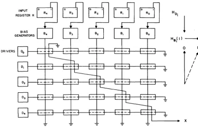
A ten by ten matrix of these AND circuits is
illus-trated in Fig. 5. For clarity, the internal circuit con-nections and devices have been omitted. In the matrix, addition is accomplished by the coincidence
of current on any pair of lines such as
A
= 5 andB = 6. When the AND circuit at this intersection is
active, its output is placed on the eleventh diagonal. For packaging purposes the designer has the choice
of packaging several AND circuits on a single
plug-gable unit. When the circuits were optimized, only
the two-way AND logic together with the output
loading conditions were known.
Let us now reexamine this same matrix from a sys-tem rather than a circuit viewpoint (Fig. 6). In this
specific matrix element only one AND circuit in the
A
=
5 column and the B=
6 row is "on." This is asystem consideration and was not known at the time
the Boolean AND circuit was optimized. The vertical
column A = 5 will now be considered as a single
element.
System-Tailored Circuits
10 1959 PROCEEDINGS OF THE EASTERN JOINT COMPUTER CONFERENCE
A
o
c
L . . . -_ _ II
L~====================18
Fig. 6-Matrix utilizing standardized "Boolean" circuits.
is illustrated in Fig. 7. For convenience, transistors have been shown, although other devices such as re-lays, tubes, cryogenic devices, etc., could have been
used. The input A supplies current to a common
con-trol which go.es to all the bases of the ten transistors.
Since only one line on the B input to the emitters is
active at any instant, only one transistor will be con-ducting. Let us now examine the addition matrix utilizing this "system tailored" circuit.
6Q)-5 cp !
- - I I
Fig. 7-System tailored circuit (CS).
Matrix Utilizing System-Function Circuits
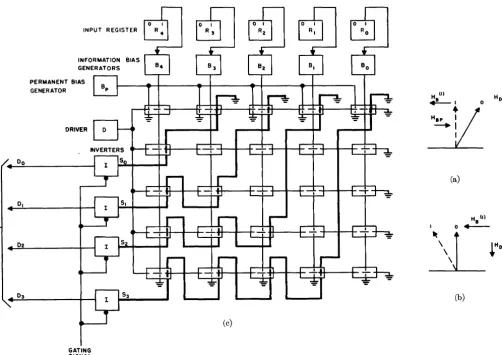
The complete matrix is again shown in Fig. 8, this time utilizing ten of the system-function circuits. The
"A" entries on the vertical axis go directly to the
common control connections of the ten AND circuits.
The" B" entries are connected to the emitters of the
ten transistors in each of the ten circuits. The col-lectors are connected to the output lines, which are functionally equivalent to diagonals in the previous matrix. Note the identical configuration of the wiring to the inputs of all ten matrix columns. The outputs
of each "system AND" circuit are connected in a
pattern which drops down to the next output line for each successive group. Thus, to add 5 to the number
entering B the sixth AND circuit is activated. The
number 6 on the B entry is moved down five units on
the output, giving a sum of 11. Although the number of transistors required in both matrix examples re-mains the same, the passive elements are eliminated and the packaging pattern for both interconnections and devices is drastically improved.
A
Fig. 8-Matrix utilizing "system function" circuits.
In the illustration the solid lines represent a layer of interconnections on the front of a printed substrate and the broken lines, a second layer' on the rear. Connections through the substrate are indicated by dots. Inasmuch as ten system-function circuits are used, ten component packages consisting of active elements only may be mounted on a single substrate that contains the complete interconnection wiring.
A computer may be described as "a bunch of wires connected by active elements." This second method of matrix design underscores that definition. Three important features become apparent in this example. First, careful attention to system-function circuits will lead to logical layouts that are much easier to express algebraically for equation-controlled manu-facturing. Second, the amount of packaging and inter-connections, and the number of elements involved can be reduced over present methods. Third, new system-function device specifications will emerge.
System-Tailored Devices
Rice: Computers of the Future 11
PRESENT
o INDIVIDUAL ACTIVE ELEMENTS
o WIRED INTERCONNECTIONS
EARLY GENERATION
o MULTI-ELEMENT "SYSTEM TAILORED" UNITS
o PRINTED OR ETCHED INTERCONNECTIONS
LATER-FILMS
o BATCH-BULK TECHNIOUES MERGING ACTIVE DEVICES AND INTERCONNECTIONS
PROBLEM____4___+ SOLUTION
FUTURE - MICROMINIATURIZATION
o SMALLEST ELECTRONIC ELEMENT IS TOTAL SYSTEM
Fig. 9 -Devices "system tailored."
In an early generation, multi-element system-tailored devices will be available. In addition, a much greater proportion of the interconnections will be etched and printed. Multi-element miniaturized com-ponents have been made available in small quantities by American Bosch Arma, the Diamond Ordnance Fuze Laboratory, Hughes Aircraft, RCA, Texas In-struments, and others. Programs in molecular elec-tronics to permit the use of plating and vacuum-deposition processes are also receiving attention. Much of this work is for military applications but will probably be available for commercial use in the near future.
The production of interconnections and active ele-ments in one continuous manufacturing process will occur with the introduction of films, either thick or thin, into systems. At this time, semiautomatic methods of manufacture will be mandatory. Here it is obvious that separate considerations of system functions, circuits, and devices may no longer exist. Magnetic coupling is used to accomplish switching in thin film cryogenic systems and speeds are very high. One suspects that nature also provides a medium speed and cost arrangement if we are clever enough to detect it.
Further in the future we may anticipate true micro-miniaturized systems constructed from automatic, computer-controlled processes utilizing bulk mate-rials. The late Professor Dudley Buck has defined a microminiature computer as: "A computer on a scale which could never be looked at in an optical micro-scope." In this technology, the cost of active elements will approximate the cost of interconnections. Logical designers may enjoy the luxury of utilizing thousands of active elements to perform logical functions of a complex nature.
One of our major objectives is to reach the future system illustrated here. Let us now consider some of the more important work to be done to make this possible.
DIGITAL DATA PROCESSING
ApPROXIMATE RELATIVE COSTS
The bar graph (Fig. 10, Line 1) shows the approxi-mate relative costs of processing data in presently available commercial general-purpose digital sys-tems. Problem preparation and programming costs are generally accepted as being approximately half of the total. The remaining costs may be .divided into two major items: electronic main-frame costs and electromechanical peripheral-equipment costs. The percentages vary from system to system, but are essentially as follows: The cost of main-frame electronics varies between 15 and 25 percent of the total, and includes the main random access storage, the arithmetic and logic unit, and controls. In the main-frame, the switching devices cost approximately one-third and the packaging (which includes circuit cards, panels, interconnections, frames, display, covers, etc.), approximately two thirds. The cost of the electromechanical portion of a system may vary between 25 and 35 percent of the total and may be divided into two parts. The first is bulk storage in-volving mechanical motion. This part includes tapes, discs, drums, etc., and their attendant electronic equipment. The second part is the input-output equipment, including communication devices.
PRESENT
GENERAL PURPOSE SYSTEMS
NEXT GENERATION
SYSTEM ORIENTED CIRCUITS AND PACKAGES 2ND GENERATION
TRANSLATION (PROBLEM TO MACHINE)
MACRO-INSTRUCTIONS
SYSTEM ORIENTED MULTI-ELEMENT SPEDAL PUlPOSE DEVICES EQUATION SPECIFIED
INTERCONNECfIONS 3RD GENERATION
PHYSlCALLY MERGED DEVICES AND INTERCONNECTIONS FUTURE
MICROMINIATURllATION
Present Generation
~ LANGUAGE-MACHINE LANGUAGE
ELECTRONIC ELECTRQ-MECH. (MAIN FRAME) (PERIPHERAL)
12 1959 PROCEEDINGS OF THE EASTERN JOINT COMPUTER CONFERENCE
System specification normally starts with a market analysis so that a potential product may be defined. Performance, storage volume, input-output equip-ment, etc., are established at this time. Available standard circuits and packages are considered during the specification of system logic. Outputs from the system design are block diagrams, or equations, or both. At this stage we do not know where each device or circuit will be placed, nor the length of intercon-nections.
In programming, present generation machines use autocoders to translate from problem language into machine language. The autocoders, in many instances, involve execution time and occupy storage space. This combination of autocoders and machine langu-age is the result of the programmer's desire to have a machine language different from the one technology is able to economically provide.
Devices used in present systems, both active and passive, are individually manufactured by semiauto-mated methods. This allows individual testing, selec-tion, and replacement in the event of malfunction.
The circuits are Boolean optimized and the minor packaging assemblages usually include several ele-mentary functions. Recent trends as evidenced in machines like the Philco TRANSAC, are toward the inclusion of more Boolean-type circuits on each plug-gable element. Interconnections are a mixture of printed cards and hand inserted wires and cables.
The major mechanical design of a system starts when logical specification and Boolean standardized circuits are available. With this information, the active and inactive elements may be located and packaged. For the first time, lead lengths become accurately known. The output from mechanical de-sign is generally a complete set of blueprints which go to the manufacturing engineering groups.
In the peripheral equipment area the bulk storage usually involves magnetics and includes much me-chanical equipment. Access to data in this type of storage is either serial-by-bit or serial-by-character. The input-output equipment is essentially mechan-ical, taking data from a keyboard to a buffer storage and, later, taking data from a buffer to a printer to produce hard copy.
Servicing is usually done by a combination of elec-trical tests and diagnostic programs. It involves locating the defective active or passive elements and substituting new pluggable cards.
The specification and design of present systems is thus essentially a serial process in which most major elements are individually standardized and then assembled to make a system. The design feedback loops, while many, have rather high impedance.
Next Generation
The next generation as illustrated by the bar in Fig. 10, Line 2, may be characterized mainly by
system-oriented design and manufacturing techniques. Commercial machines will probably remain general-purpose in nature.
The bars illustrating approximate relative cost on this and succeeding generations does not necessarily indicate that the cost of an equivalent advanced machine will be reduced. The length of the bars repre-sents the relative proportionate cost for each of the major elements in a system for a particular genera-tion. Past experience has shown that as more power-ful techniques become available we solve larger problems; therefore, we have an option of obtaining more computing for our millions or reduced costs for the same amount of processing. This is obviously a designer's choice and will be adjusted to suit require-ments as he specifies a particular system.
A major change will occur in the specification of systems. Logic and circuits will be merged to produce new system function circuits utilizing standard de-vices. The physical location of components, the inter-connection lengths and paths, and layout of the package will be specified as an integral part of logic. To attain these objectives a new "system-function algebra" is necessary. This algebra, which will begin with the logical Boolean expressions, must be en-riched to include the active and passive device char-acteristics, the physical location of all components, the interconnection paths and lengths, and timing.
Programming in this generation will be done with more powerful macro-type instructions. Machine language instructions will approximate the level typified by coding systems such as FORTRAN. Relatively speaking, more hardware will be in the instruction controls with the objective of making programming easy and fast.
Improved single-function devices and some use of multifunction devices may be anticipated.
A maj or change in packaging as well as in logic-circuit specification will occur in this generation. Complete system functions will be packaged on one replaceable element. Interconnections will be etched, printed, evaporated, or batch produced by other automated techniques. Manufacturing equipment, methods, and mechanical design techniques must undergo the appropriate changes.
Service will be accomplished by locating and
replac-ing malfunctionreplac-ing major system functions. If the
individual devices are expensive, they may be re-placed at a testing and service center so that the
system function may be returned to stock. If not,
the whole unit may be discarded. Extensive built-in checking and automatic program diagnosis will be included. The logic of the machine will require more redundancy for checking and diagnostic purposes.
Rice: Computers of the Future 13
Second Generation
Two major changes characterize the second gener-ation systems. (Fig. 10, Line 3). First, system-tailored
multi-element devices will be used extensively. This
will influence mechanical design, packaging, and manufacturing equipment. Secondly, special-purpose
machine systems to solve classes of problems will be
made on the same manufacturing line. The logical specification of these machines will be generated by computers utilizing system-function algebra. Exten-sions of the algebra will control the manufacturing setup. This combination will drastically reduce design and production lead times and cost of the product.
The availability of special-purpose systems will ease programming difficulties through the use of application-tailored languages to solve related classes of problems.
System-function design techniques and devices will be applied to bulk storage. For input-output, elec-tronics will replace mechanical equipment wherever possible.
Noon-line service will be performed since the machine will be able to select alternate logical paths in the event of a malfunction. At inspection periods, previously-flagged defective system elements will be removed and replaced.
Third Generation
The true revolution begins in the third generation. (Fig. 10, Line 4). Here, device, package, and
inter-connections are inseparably merged. Major system
functions will be produced from bulk materials in computer-controlled continuous manufacturing proc-esses. Techniques such as vacuum deposition, electron-beam writing, spraying, printing, etc., will be utilized, depending on device technology chosen relative to the speed and cost range desired. The use of three-dimensional connections will alter packag-ing concepts. Miniaturization for complete systems may now be realized. This miniaturization will allow dramatic increases in the number of active elements a vailable for both logic and storage.
The availability of vast amounts of homogeneous storage with internal logical capabilities will drastic-ally alter programming methods. In particular, built-in symbolic addressing will eliminate the in-efficient and tedious housekeeping associated with
present-day machines. Coupled wit~ special-purpose
instruction sets, this will allow machine language to approximate problem language.
The input-output equipment will now be reduced to that which is used to communicate with humans or from machine to machine, since bulk storage is now merged with the main frame.
Future Generation
We may envision a few aspects of future
gen-erations now (Fig. 10, Line 5). True rtu~crominiatur
ization meeting Professor Buck's definition will be
realized. Self-organizing systems will become possible due to microminaturization and better understanding of the logic involved. The use of self-organizing sys-tems to find optimum solutions to problems will allow us to synthesize more economical, special-purpose systems for on-line use.
For programming, we may anticipate that machine language will approximate or equal human language if we have progressed properly to this point and if we use self-organizing systems appropriately. A major change in input-output techniques is required. Voice and pattern recognition, and vastly improved display and printing systems are needed.
In this generation, service will be accomplished by throwing the whole computer away.
In summary, to progress from the present day data processing capabilities to more desirable future sys-tems, we require greatly increased logical capabilities, vast amounts of storage, improved input-output methods and more speed. All these elements tend to require microminiaturization, batch-bulk processing, automated logical synthesis, and equation-controlled manufacturing. Consequently, both speed and system cost require and benefit from this revolution.
EJ----,
EQUATIONS
FUTURE COMPUTER "ELECTRONICS"
STANDARDIZED ON.
o BULK RAW MATERIALS
o MERGED DEVICES AND INTERCONNECTIONS o SYSTEM FUNCTION ALGEBRA
o MANUFACTURING METHODS-COMPUTER CONTROLLED
OBTAINING.
o EFFICIENT SPEaAL PURPOSE SYSTEMS o PRODUCED RAPIDLY AND ECONOMICALLY
RESULTING IN'
o MORE BRAINPOWER ON DEFINING PROBLEMS
o CHEAPER PROBLEM SCLUTION
Fig. ll-Future computer "electronics."
CONCLUSION
Future computers (Fig. 11) will be standardized as follows:
1. Interconnections and active devices will be made
Service will be simple because automatic error detection and correction by the machine will allow continuous operation. Defective elements will be 2. replaced at the next service period.
in a continuous process from bulk raw materials to finished product.
14 1959 PROCEEDINGS OF THE EASTERN JOINT COMPUTER CONFERENCE
3. System-function algebra will be used to specify all aspects of design.
4. Completely automated, computer-controlled man-uf acturing methods will be used.
From these techniques we will obtain efficient special-purpose digital data processing systems. They will be produced economically with short design and construction lead-times through complete automa-tion. This will result in more brain power being devoted to discovering and defining new problems, and in their cheap, efficient solution.
DISCUSSION
J. H. Felker: (AT&T) I would like to hear you complete the job of
prophecy, Mr. Rice, and give us some idea of the timetable you en-vision for these first, second, third (and) fourth generation machines.
Mr. Rice: I have given that question considerable thought. We are
working on the next generation right now in many research labora-tories. The universities are probably ahead in some respects in their thinking on research in this area. It is not necessarily true that each generation requires the specific items at the same time as shown in the paper. If we develop microminiature computer devices ahead of new programming techniques, they may be utilized early. I suspect, and this is a personal observation, that the first models of micro-miniature computers are ten years off and the other items for the next generation are scattered from three to five years away in production. This is a guess on my part.
Mr. Felker: Thank you. With the three year period it takes to design
and get production of the conventional computer, how can you antic-ipate anything as drastically different from what we do today as your microminiature computer in only ten years? Where are the people and the knowledge that will permit this in ten years?
Mr. Rice: I agree that the ten years is probably on the optimistic
side. However, you will note that the methods of specification for what I call the "algebra" of these systems includes the device char-acteristics and the physical layout. This implies that much of our early work is in development of a new "system function algebra." Once this algebra is automated, the design of new systems will be done rapidly, and we will be less dependent on present day design techniques.
H. Richmond (System Development Corp.): What is meant by "machine language is approximately problem language"? What is done in this case if a new variable is needed and your hardware is built?
Mr. Rice: We have to recognize in our future designs that problem
language is not static. In other words, FORTRAN, if I may use that example, has already proven that we need extensions. There-fore, I think the computer designers - and I happen to be one who believes this - must design control sections which admit that pro-gramming language is dynamic. We should be able to incorporate new instructions without going back and completely rewiring. There is much research work to be done on the type of control situation implied. I, for one, am very anxious and excited about working in this area.
J. Feitler (J BM): What about analog-computer logic with
digital-computer hardware with many arithmetic elements (100 to 1000-plus arithmetic elements) using microminiature components at "3rd generation level"?
Mr. Rice: I am not certain that I fully understand the implication
of analog-digital computer hardware. If you mean we are working on separate portions of the problem in parallel, using the accuracyob-tained by digital techniques, I think there are existing machines showing this tendency. Assuming that we can assemble thesE: systems to solve the classes of problems we have to solve, this is an interesting area for development. As to the 3rd generation I don't think I would hazard a guess.
L. B. Harris (GE): How do you propose to implement self-checking of system functions, that is, to pin-point the trouble?
Mr. Rice: Much work is being done on this subject in various research
and development laboratories. I think we have to reanalyze where we want to spot errors. For example, in the talk a complete arith-metic process unit is shown as a single system function. I purposely chose the one-out-of-ten code in this example, because it is possible to put a single check device at the far end of the system. If more than one pulse arrives, there is trouble. If less than one pulse arrives, there is trouble. If only one pulse arrives, I would assume it is correct, because the logical paths do not cross. Much research remains to be done in this vrea, so I don't have a complete answer. I believe we should analyze how small or how large an element should be when we look for trouble. We should probably diagnose trouble in major ele-ments rather than at the Boolean circuit level. We should also examine our need for a single code throughout a complete system. That is to say, do we need the same bit code in the processing ele-ment that we need in bulk storage. There are many ways of tackling the problem, and I think we will have to look to future generations for the complete answer.
C. H. Propster (G E): What reason do we have to think a self -organizing computer will ever be produced?
Mr. Rice: Perhaps you are in a better position to answer this question
than I am. I believe that two things are necessary before self organiz-ing systems are more tl>an (if I may use the expression loosely) ideas: First, we have to really understand what we want to do in the system to make it self-organizing. This is the lof!;ical consideration. Secondly, it is fairly obvious it will take lots of components, so we have to develop the manufacturing techniques to produce large numbers of components economically. Whether or not we will get to the most blue-sky systems is hard to predict, and I will shy away from that. I think that manifestations of self-organizing systems are possible, and that they will be developed.
P. J. Scola (GE): On the throw-away computer, what will the input-output wiring look like? Will there be any input-input-output?
Mr. Rice: This is a very difficult question to answer, even in an hour
and a half. At all stages in the future. we will need communications from humans to the machine. We hope that voice recognition will allow us to get from a human to the machine language. In the throw-away portion, I am specifically referring to the electronic elements of the computer: that which we now know as the main frame. In partic-ular, the capacity of the bulk storage associated with the main frame is drastically increased. This will reduce the peripheral equip-ment such as tape, discs and so forth. So in effect we will be throwing that section of I/O away. The concept of throwing away is also hard for me to accept. However, I ask myself how are we going to repair microminiature devices; and I come up with the answer that we had better make them cheap enough so we can throw them away.
F. Panch: Would you care to speculate on what kind of computers might be in use twenty to forty years from now?
Mr. Rice: Frankly, I ,have trouble envisioning what I call future
computers. I think that the major changes beyond these generations will be in new uses for computing systems. If we can make computer language approximate human language, or at least equal problem language, the challenge will be in what we do with the system and in making the systems cheaper so we can use them more frequently.
R. J. Brousseau (U of C): In saying that computer language should approach problem language' in future computers, are you suggesting that the computer hardware should accomplish the functions now being borne by present automatic programs, such as mn~monic instructions, symbolic memory names?
Mr. Rice: The answer to that question, in terms of generalities, is yes.
1959 PROCEEDINGS OF THE EASTERN JOINT COMPUTER CONFERENCE 15
Negative-Resistance Elements as Digital Computer
Components*
MORTON H. LEWINt
INTRODUCTION
I
N DETERMINING the maximum repetition rateof .a g~ven sw~tching circuit, the response of the
sWItchIng deVIce and the effect of other circuit parameters (including stray elements) must be taken into account. Although the switching speed is ulti-mately limited by the device, in many cases one never reaches this theoretical lllaximum because cir-cuit limitations play the dominant role. To solve this problem, one is forced to devise extremely simple cir-cuits with few components in order to minimize the effect of stray reactance. The use of two-terminal negative-resistance elements allows one to do this.
Shockley and Mason! have proposed that the ulti-mate high-speed semiconductor amplifying device is a two-terminal negative-resistance element. They reason that, since the speed of semiconductor com-ponents is basically limited by the transit time of carriers, the physical dimensions of devices operating in the highest frequency ranges must be extremely small. In the limit, fabrication problems dictate two-terminal active elements, where only one dimension need be small.
This paper is first concerned with the general problem of using two-terminal negative-resistance devices as the only active switching elements in a digital system. Specific circuits are then discussed
using a particular voltage-controlled
negative-resist~
ance device as an example. Much of this treatment can be adapted to other negative-resistance elements.
GAIN
A combinational switching circuit is defined as a circuit whose outputs depend only on the present in-puts. This is to be distinguished from a sequential switching circuit in which the outputs depend not only on the present inputs but also on the past his-tory of inputs. Thus, a combinational circuit, by definition, has no memory.
Consider a system of combinational circuits
em-* This work was supported by the Bureau of Ships, U. S. Navy, under Contract NObsr 77523 with RCA. It is the basis of a dis-sertation to be submitted in partial fulfillment of the requirements for the Ph.D. degree at Princeton University, Princeton, N. J.
t RCA Laboratories, Princeton, N. J.,and Department of Elec-trical Engineering, Princeton University, Princeton, N. J.
1
w:
Shoc~ey and W. P. Mason, "Dissected Amplifiers UsingNegatIve ResIStance," Journal of Applied Physics, Vol. 25, No.5,
p. 677; May 1954.
ploying negative-resistance devices as the active switching elements. The requirement of no memory dictates either monos table operation of the negative-resistance elements or bistable operation with a built-in reset to eliminate storage. (The possibility of combinational circuits composed of sequential sub-circuits is ignored on the grounds that such compli-cated circuits will reduce the maximum speed of the system.)
For the case of monostable operation, if one re-moves anyone of the negative-resistance elements from the circuit, measures the static V-I character-isticseenlookinginto the rest of the circuit from its two terminals and then superimposes this on the negative-resistance characteristic, there is always only one stable intersection, for all input combinations. For an all-passive circuit, such as a conventional diode gate, one intersection (operating point) is assured. Assume that this measured characteristic can be approxi-mated by a straight loadline, in the region of interest
(A design to insure monostability is feasible only if
this characteristic is "well-behaved" (i.e., monotonic)
in the region where it intersects the negative-resist-ance characteristic.) This leads to a simple situation which can be directly analyzed.
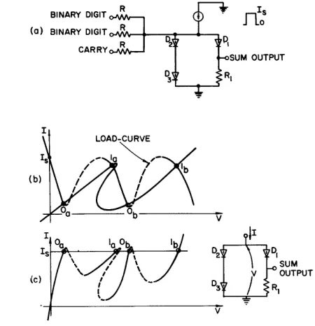
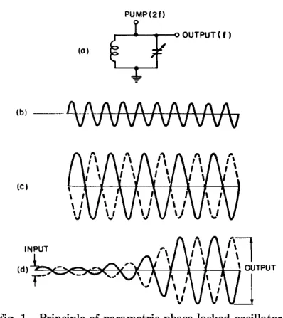
Typical voltage-controlled and current-controlled negative-resistance characteristics are shown in Fig. la. The two states for each device are most conven-iently chosen as operation in the two positive-resist-ance regions on both sides of the negative-resistpositive-resist-ance region. Thus, for a voltage-controlled element, the state is defined by the voltage across the device, and for a current-controlled element by the current through it. Under the conditions described above, the circuits to be analyzed become those shown in Fig. lb.
The combination of R and the power source
repre-sents the Thevenin equivalent of the linearized meas-ured characteristic.
Monostable operation can be achieved in two ways as indicated by the load-lines in Fig. la. In the first
case, labeled "I", R
<
Rn min for thevoltage-con-trolled element and R
>
Rn max for thecurrent-con-trolled element, where Rn =
I
dV / dII
in the negativeresistance region. In the second case, labeled "II", R
16 1959 PROCEEDINGS OF THE EASTERN JOINT COMPUTER CONFERENCE
VOLTAGE-CONTROLLED CURRENT-CONTROLLED
Fig. l-(a) Load-lines for monostable operation. (b) Equivalent cir-cuits. (c) Load and signal source included. (d) Addition of reactive element.
A DC-coupled system with no reactive elements will be assumed. The output terminals and equivalent
load resistance RL are shown in Fig. lc. Input signal
sources are also included. R L represents the load
fur-nished by other gate circuits in the net. Rl represents
the contribution to R of the internal parameters of
the circuit under consideration. The series or parallel
combination of Rl and R L, as appropriate, yields R.
For the voltage controlled case, RL can vary from ex>
to some minimum value and for the current-controlled case, from 0 to some maximum value. The fact that
R L varies as indicated is a direct result of the
two-terminal nature of all components. For example, an examination of the possible configurations using vol-tage-controlled elements reveals that, in general, the output current from a stage in a given state depends on the states of the circuits being driven.
The values of Rl and 18 or VB must be chosen to
assure monostability for all loads. Thus, they must be chosen such that only one intersection (of the
type shown in Fig. la) occurs for RL = ex> in the
voltage-controlled case and RL = 0 in the
current-controlled case. If these conditions are satisfied,
monostable operation is assured for all R L.
Recall that any reactance in the circuit is assumed negligibly small. For case I, looking into the circuit
from the output terminals, the load resistor RL sees
a net positive resistance for all voltage-current condi-tions. Hence, there is no possibility that an increment of energy delivered to the load will be greater than that supplied by the signal source, for any value of
RL • For case II, assuming a rectangular signal pulse
which raises the load-line sufficiently to cause the operating point to switch to the other
positive-resistance region, a simple calculation 2 reveals that
the input energy is at least as great as the output energy. Thus, the requirement of monostability, in the absence of adequate reactance, leads to a circuit which has no gain.
If one now allows the use of appropriate reactive
elements (i.e., capacitance in parallel with the
cur-rent-controlled device and inductance in series with the voltage-controlled device), as shown in Fig. ld, gain can be achieved. Note that the added reactance cannot simply be greater than zero but must be greater than a certain minimum established by stray elements and the properties of the negative-resistance device. (For an AC-coupled system, the reactive cou-pling elements must also be taken into account.) In this case the gain ariRes from the fact that energy stored in the reactive element is delivered to the load when the negative-resistance device is triggered by a small signal. Such circuits have been treated in the
literature3
,4.5. It is shown there that the recovery
time associated with the reactance is a factor which limits the maximum repetition rate of the circuit. Bistable-with-reset operation allows one to achieve gain without the use of reactive elements. Since the furnishing of a reset signal may be considered to be an additional function of the power supply, effec-tively a time-varying power source is now being con-sidered. One possible arrangement is to let the power supply (current or voltage) deliver a continuous train of rectangular pulses, such that during each pulse (excitation) the negative-resistance device can go to either one of its two states, depending on input conditions. The "reset" is then the termination of the excitation pulse. It can be seen that such a power supply also serves as a master clock. If one now
calcu-lates6 the transition and recovery times for such a
system and compares this to the system with DC power supplies and reactive elements, it is evident that the former scheme has the higher maximum repetition rate.
DIRECTIONALITY
Another fundamental problem is concerned with making the system unilateral. For example, since the negative-resistance element is a two-terminal device, when one terminal is grounded, the other must act as both the input terminal and the output terminal. One must therefore provide some means to dictate
the direction of flow of information in the system (i.e.,
to make a circuit directional, so that a signal
propa-2 See Appendix.
3 B. G. Farley, "Dynamics of Transistor Negative Resistance
Circuits," Proc. IRE, Vol. 40, pp. 1497-1508; Nov. 1952.
4 A. E. Anderson, "Transistors in Switching Circuits," Proc. IRE,
Vol. 40, pp. 1541-1558; Nov. 1952.
Ii A. W. Lo et aI., "Transistor Electronics"; Prentice Hall, 1955.
Lewin: Negative-Resistance Elements as Components 17
gates Jrom input to output). Some possible techniques
for achieving directionality include use of passive elements such as Hall-effect couplers or gyrators, use of non-linear interstage coupling elements such as conventional diodes, synthesis of three-terminal cir-cuit configurations with some unilateral properties, and separation of input and output functions in time using a time-varying power supply. Some of these techniques, as applied to circuits involving voltage-controlled elements, are discussed in more detail fol-lowing the treatment of basic logic circuits.
POWER SUPPLY
Assuming the bistable-with-reset mode of opera-tion, with the momentary removal of power supply excitation as the method of resetting, the waveform shown in Fig. 2a represents an acceptable source waveform. The sequence of operations performed by
each stage is th~n as follows: having been reset, a
given circuit is energized to an initial state. If the
combination of inputs presented to it is favorable, it will switch to its other state. The state of the circuit is then detected by the next stages. Finally, the cir-cuit is reset, energized again and ready to receive a new combination of inputs.
~RI
SOURCE:
(0)
~A
I
I
I
CPA
~B
I
rTrJ ITI~CPs
I
I
c
~cb
IT2~CPc
I
(b)
Fig. 2-(a) Power supply waveform. (b) Three-phase power source.
If the entire system is powered from the same
source, all circuits are reset simultaneously. The energizing pulses must then be wide enough to allow signals to propagate from the inputs of the system to its outputs, so that the repetjtion rate is limited by the longest signal propagation time expected. To in-crease the repetition rate, the system is broken up into small groups of gates such that each group is reset immediately after it has performed its function.
A sequence of resets is then required in order that
in-formation will continue to propagate and will not be erased. These requirements can be satisfied by a multiphase power supply such as, for example, the three-phase waveform shown in Fig. 2b. Using this method, a given gate or group of gates is powered by
one phase, drives other circuits powered by the next phase and is driven by still other circuits powered by the previous phase. The excitation pulses overlap in time such that information propagates between two stages during the period when both are energized
simultaneously. Considering the block B in Fig. 2b,
one can see that the beginning of its supply pulse,
T1, corresponds to an "input" region and the end of
the pulse, T2 , to an "output" region. The three-phase
arrangement shown is characterized by the fact that there is always a group of circuits in the de-energized condition at any given moment. As a result, in many cases spurious signals are prevented from propagat-ing. The similarity between this scheme and the
multiphase clock systems used in conventional ma-chines is only superficial. Here the clock source is also the power supply.
GENERALIZED ANALYSIS
Load-curves
Consider a two-terminal "black-box" A whose
static V, I characteristic is given by either I A = gl(V A)
or V A = /1(1.1). The box may simply hold a single negative-resistance element or may include a more complicated arrangement of elements whose
compos-ite two-terminal V, I characteristic is given by the
above equations.
/1
(or gl) may be any continuousfunction and is not single-valued in both V and I if
there are any negative-resistance regions. Now
con-sider a second two-terminal "black-box" B whose
static V,1 characteristic is given by either I B =
g2(V B) or VB = /2(1 B). This will correspond to the
device which determines the load-curve. If g2(V B) =
V B/R (i.e., /2(1 B) = I BR), then the device is the
re-sistor R, ~entioned before, and the load-curve is a
straight load-line. In general, however, both Jl and
/2
are non-linear, negative-resistance characteristics. The two cases of interest are the following configura-tions:
(a) A constan t-vol tage source V 8 across the series
combination of elements A and B.
(b) A constant-current source 18 feeding the
parallel combination of elements A and B.
The pertinent equations are:
Case (a) Case (b)
IA = IB V4 = VB
VS=VA+VB Is = lA
+
IBVA =Jl(IA) [1] lA = gl(V A)
VA = Vs - /2(I A) [2] lA =Is -g2(V A)
The equilibrium points or quiescent operating points for a circuit are determined by the intersection points
of the two curves