drives
.
White Rose Research Online URL for this paper:
http://eprints.whiterose.ac.uk/864/
Article:
Wipasuramonton, P., Zhu, Z.Q. and Howe, D. (2005) Improved current-regulated delta
modulator for reducing switching frequency and low-frequency current error in permanent
magnet brushless AC drives. IEEE Transactions on Power Electronics, 20 (2). pp.
475-484. ISSN 0885-8993
https://doi.org/10.1109/TPEL.2004.842957
eprints@whiterose.ac.uk https://eprints.whiterose.ac.uk/
Reuse
Unless indicated otherwise, fulltext items are protected by copyright with all rights reserved. The copyright exception in section 29 of the Copyright, Designs and Patents Act 1988 allows the making of a single copy solely for the purpose of non-commercial research or private study within the limits of fair dealing. The publisher or other rights-holder may allow further reproduction and re-use of this version - refer to the White Rose Research Online record for this item. Where records identify the publisher as the copyright holder, users can verify any specific terms of use on the publisher’s website.
Takedown
If you consider content in White Rose Research Online to be in breach of UK law, please notify us by
IEEE TRANSACTIONS ON POWER ELECTRONICS, VOL. 20, NO. 2, MARCH 2005 475
Improved Current-Regulated Delta Modulator for
Reducing Switching Frequency and Low-Frequency
Current Error in Permanent Magnet
Brushless AC Drives
Pongpit Wipasuramonton, Zi Qiang Zhu
, Senior Member, IEEE
, and David Howe
Abstract—The conventional current-regulated delta modulator (CRDM) results in a high current ripple and a high switching fre-quency at low rotational speeds, and in low-frefre-quency current har-monics, including a fundamental current error, at high rotational speeds. An improved current controller based on CRDM is pro-posed which introduces a zero-vector zone and a current error cor-rection technique. It reduces the current ripple and switching fre-quency at low speeds, without the need to detect the back-emf, as well as the low-frequency error at high speeds. The performance of the modulator is verified by both simulation and measurements on a permanent magnet brushless ac drive.
Index Terms—Brushless ac drive, current control, modulation, pulse width modulation (PWM).
I. INTRODUCTION
T
HE performance of the current loop is one of the most crit-ical aspects of an ac drive, in terms of its dynamic response and accuracy. Numerous current control techniques have been developed [1], which may generally be classified as hysteresis, linear and predictive current control [2].Conventional hysteresis control results in an excellent tran-sient response and is insensitive to load variations and relatively simple to implement [1]. However, it has several limitations. For example, the current error can be twice the hysteresis band due to mutual coupling between motor phases, while the resulting switching frequency is dependent on the motor parameters, the dc bus voltage and the hysteresis band. In addition, limit cy-cles, which cause bursts of high-frequency switching, can occur when the back-emf is small. To overcome such problems, space vector control with information on either the direction of the back-emf vector [3] or the current error derivative [4] may be employed. An additional wider hysteresis band could also be used [5], [6].
Linear PI current control is also simple to implement, but results in inherent tracking errors, both in amplitude and phase. Moreover, it provides relatively poor transient performance, whilst the controller tuning is sensitive to the drive system parameters. In predictive current controllers, the current error is
Manuscript received January 6, 2004; revised September 9, 2004. Recom-mended by Associate Editor a. Emadi.
The authors are with the Department of Electronic and Electrical Engineering, University of Sheffield, Sheffield S1 3JD, U.K. (e-mail: elp01pw@shef.ac.uk; z.q.zhu@sheffield.ac.uk; z.q.zhu@ieee.org; d.howe@shef.ac.uk).
Digital Object Identifier 10.1109/TPEL.2004.842957
predicted at the beginning of each sampling period on the basis of the actual current and the motor parameters. The required in-verter voltage for the next modulation period is then calculated to minimize the predicted current error. However, although good steady-state and transient performance can be achieved, generally accurate knowledge of the system parameters is required.
Another form of hysteresis control is the current-regulated delta modulator (CRDM) [7], [8], which uses comparators without hysteresis whose outputs are sampled in discrete time. Consequently, the maximum switching frequency is limited by the sampling frequency. Moreover, it is also simple to implement digitally, in either software or hardware. However, significant low-frequency current harmonics and a fundamental current error may exist due to the influence of the back-emf [8]. Although increasing the sampling frequency can mitigate this problem, the switching frequency increases when the back-emf becomes small. It should also be noted that, since the three-phase current errors sum to zero, the switching state signals are never of the same logic, i.e., a zero voltage vector is never selected [7], [8].
In [7], an improvement on the basic CRDM was proposed in which a new voltage vector adjacent to the preceding one was selected and a zero voltage vector zone was introduced. However, although the current ripple was reduced significantly, low-frequency current harmonics still existed. More recently, improved current controllers based on a CRDM have been proposed [9], [10]. In [9], the desired voltage vector was calculated by means of a predictive current control method, the discrete voltage vector which is closest to the desired one being selected for the next sampling period. However, although this gave good results, in terms of reducing the current ripple, the switching frequency and the low-frequency harmonics, the calculation was relatively complex and back-emf information was still required. In [10], possible actual current vectors which would be produced by discrete voltage vectors were calculated, and the voltage vector which resulted in the actual current being closest to the reference value was selected for the next period. However, this approach required knowledge of the load parameters.
In this paper, an improved CRDM-based current controller is presented which not only reduces the current ripple and switching frequency, especially at low rational speeds, without the need for back-emf information, but also reduces both the low-frequency and fundamental current errors at high rotational
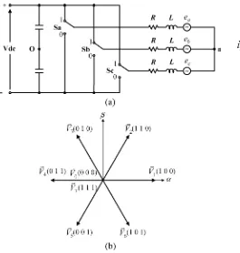
Fig. 1. (a) Simplified voltage source inverter and (b) voltage vectors.
speeds. Before describing the proposed controller and its im-plementation on a low cost fixed-point DSP, however, the basis of the conventional CRDM is presented. The performance of both controllers is then compared, by means of simulations and experiments.
II. CONVENTIONALCRDM
A schematic of a PWM inverter for a three-phase brushless ac drive is shown in Fig. 1(a). In general, the machine equation may be expressed in a space vector form as
(1)
where is the terminal voltage vector, is the stator current vector, is the back-emf vector, and and are the stator winding resistance and inductance, respectively. All the vector notations in (1) can be defined by
(2)
where , and , and are machine phase vari-ables. The current error vector is defined such that
(3)
where
(4) (5) (6)
in which , and are the reference phase currents and , and are the actual phase currents. When the machine is
con-Fig. 2. (a) Basic diagram of conventional CRDM and (b) resultant voltage vectors.
nected to a voltage source inverter, the terminal voltage vector can be represented as
(7)
where is the dc bus voltage, and , , and are the switching-state signals. Combinations of switching-state signals , and lead to eight switching states for the voltage vec-tors, as defined in
(8)
The voltage vectors are shown in Fig. 1(b), two of which are zero vectors, i.e., and , and six are nonzero vectors, each having the same magnitude of .
Fig. 2 shows a schematic of the conventional CRDM [1], in which the switching state signals are determined solely by the respective polarities of the three-phase current errors, whilst the magnitude of these errors is not taken into account. Hence, at the nth sampling instant, the output voltage vector , which is applied during the period, can be determined from the sampled current error vector as
(9)
where
(10)
and
[image:3.594.70.547.61.344.2]WIPASURAMONTONet al.: IMPROVED CURRENT-REGULATED DELTA MODULATOR 477
Since the current errors are never of the same sign, only a nonzero voltage vector is applied during each sampling period. Therefore, can also be expressed as
(11)
Note also that is the unit vector in the sector in which is located, as defined in Fig. 2(b). In the example shown in Fig. 2(b), is the resultant voltage vector since
falls in sector 1.
If the sampling frequency is sufficiently high, (1) can be expressed in discrete form as
(12) where and are the current deviation vector and the sampling period, respectively. It should be noted that since is evaluated in each sampling period, its magnitude indicates how fast the current vector magnitude is changing. Since a zero voltage vector is never applied, the magnitude of is generally much larger than that of . In addition, because the back-emf is small, at low rotational speeds (12) can be approximated as
(13)
Furthermore, since the back-emf predominates over the winding resistance voltage drop, at high rotational speeds (12) can be approximated as
(14) Fig. 3 shows examples of the current deviation vector according to (13) and (14). As indicated by (13) and Fig. 3(a), at low rota-tional speeds the magnitude of in each direction is constant, and equal to
(15)
where is the maximum magnitude of the cur-rent deviation vector. At high rotational speeds, however, as in-dicated by (14) and Fig. 3(b), the magnitude of in each direc-tion is different, due to the influence of the back-emf. If a voltage vector having the opposite polarity to the back-emf is applied, the magnitude of increases, compared to that of (15). Thus
(16)
where is the maximum magnitude of the cur-rent deviation vector.
[image:4.594.317.531.60.458.2]In steady-state operation, the actual current tracks the refer-ence current . At low speeds, however, although the steady-state current error is close to zero, a high-frequency current ripple exists. Also, whenever the instantaneous current error ap-proaches zero at any sampling instant, a large current error re-sults at the next instant, due to the constant magnitude of ,
Fig. 3. Typical current deviation vectors in one sampling period: (a) without and (b) with the influence of the back-emf. (a) Low speed operation. (b) High speed operation.
according to (15). Similarly, at high speeds, a large current error is possible whenever a voltage vector whose direction is oppo-site to that of the back-emf is applied. When this occurs, it may take several sampling periods for the actual current to reach the reference value once again. Although this causes a reduction of the switching frequency, it results in low-frequency and funda-mental current errors.
III. PROPOSEDCURRENTCONTROLLER
A. Modified CRDM
If the zero voltage vectors, and , are employed in the control strategy, (13) and (14) can be modified to
(17)
at high speeds (18)
To reduce both the high-frequency ripple and the switching frequency during steady-state operation, an appropriate voltage vector should be selected during each sampling period. In this regard, it is worth noting that the electrical time constant is generally much larger than the sampling period . Hence, at low speeds, a slow current change results when a zero vector is applied. At high speeds, (18) shows that the current deviation depends on the application of a voltage vector during each period whose value varies according to the back-emf. In [3], the back-emf information was derived by using a rotor position sensor and detecting the direction of rotation. In [9], the back-emf was estimated by a relatively complex algorithm, which necessitated the use of a floating-point DSP.
In the proposed modified CRDM, the voltage vector selection is achieved by introducing a zero-vector zone, as illustrated in Fig. 4(a). This can be expressed by
and for or
[image:5.594.307.549.65.388.2] [image:5.594.79.291.119.228.2](19) where is the zero vector boundary. In other words, a zero vector is applied at any sampling instant at which the current error vector falls inside the boundary. By using this strategy, at low rotational speeds, most sampling periods are occupied by zero vectors, whilst at high rotational speeds, the application of a nonzero vector of opposite polarity to that of the back-emf is replaced by a zero vector, without the need for back-emf information. Fig. 4(b) shows a schematic of the modified CRDM strategy according to (19). On the one hand, if all the phase current errors are less than , the comparators result in “ .” However, selection of the zero vector at the next output state depends on the previous voltage vector, i.e., at most, only one switching-state signal is allowed to change for the next zero vector. This is referred to as optimum zero-vector selection. On the other hand, if any current error exceeds the band, an appropriate nonzero vector whose direction reduces the current error magnitude is used. In the steady state, considering (17)–(19), and assuming that the magnitude of the back-emf never reaches , it will be seen that (low speed) is still governed by (15). However, as mentioned earlier, since a nonzero vector having the opposite polarity to that of the back-emf is never applied, the magnitude
Fig. 4. Modified CRDM. (a) Operating principle. (b) Schematic.
of the current deviation vector never reaches , i.e.
(20)
The value of will be discussed later.
To sum up, in steady-state operation, the proposed control strategy reduces the magnitude of the current ripple and also the switching frequency by:
1) avoiding the use of nonzero voltage vectors, which result in a large magnitude current deviation without the need for back-emf information;
2) applying zero voltage vectors.
It should be noted that, together with the selection of a voltage vector adjacent to the previous one, a similar zero-vector zone was introduced in [7]. However, the zero-vector zone was considered only if the previous state was zero. It was also stated that the existence of the zero-vector zone is not critical, since it does not improve the overall rms current error. However, it has been found that although the existence of the zero-vector zone decreases high-frequency harmonics, it also increases low-fre-quency harmonics and the fundamental current error. Hence, it has been suggested that the value of the zero-vector boundary should be zero if a sufficiently high sampling frequency is employed.
WIPASURAMONTONet al.: IMPROVED CURRENT-REGULATED DELTA MODULATOR 479
Fig. 5. Current error correction.
Although low-frequency harmonics and a fundamental current error are introduced, as mentioned earlier, these can be reduced by using the current error correction technique which is dis-cussed in the following section.
B. Current Error Correction
In some modulation techniques, such as the conventional CRDM and the proposed modified implementation, the re-sultant current error consists not only of a high-frequency component which results from the inverter switching opera-tions, but also a low-frequency component which is influenced mainly by the back-emf. Considering phase-a, by way of example, therefore, the phase current error can be written as
(21)
where is the high-frequency component of the current error, resulting mainly from the switching frequency, and is the low-frequency component arising from the limitations of the modulation strategy. By extracting from the current error which is being modulated and feeding it back positively to the reference, (21) can be modified to
(22)
As clearly evident in (22), the low-frequency component of the current error is then eliminated. This operation is illustrated in Fig. 5, in which it also shows an equivalent representation to highlight the ‘current error correction’ strategy. The low-pass filter time-constant is not difficult to specify because the band-widths of and are quite different. In the frequency do-main, the transfer function of the current error correction can be expressed as
(23)
[image:6.594.318.532.64.262.2]where is the phase-a corrected current error. It will be evident from Fig. 6 that the current error correction is equivalent to a PI controller, in which the P-gain is unity and the I-gain is .
Fig. 6. Equivalence of the current error correction.
Fig. 7. Proposed current controller.
Typically, is very small (in this study, the value of is 200 s). As a result, the I-gain is relatively high.
C. Developed Current Controller
The complete structure of the proposed current controller, which combines the modified CRDM with the proposed cur-rent error correction, is shown in Fig. 7. During steady-state, the corrected current error for each phase is generated by the cur-rent error correction and is then input to the modified CRDM. By using this combination, low-frequency current errors are re-duced by the current error correction, whilst the high-frequency current ripple, and, hence, the switching frequency, is reduced by the modified CRDM. However, the presence of the integrator in the current error correction degrades the dynamic response of the control system in that a current overshoot results from a cur-rent step command. Hence, an appropriate technique for tran-sient operation, which is similar that proposed in [4], [11], is employed to minimize the current error as quickly as possible. When a large current error occurs, it is detected by the transient boundary , and the process of generating the voltage vectors is then taken over by the transient operation, which is the same as for normal operation of the conventional CRDM. The inte-grator is also reset during this time in readiness for steady-state operation.
[image:6.594.302.552.298.425.2]Fig. 8. DSP-based SPMSM drive. (a) Vector controlled SPMSM drive. (b) Time sequence of voltage vector generation.
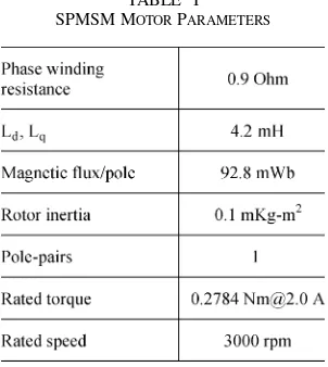
TABLE I
SPMSM MOTORPARAMETERS
conventional CRDM if . To achieve a steady-state per-formance which is superior to that of the conventional CRDM under all operating conditions, the value of is assigned to be the maximum magnitude of the current deviation vector at low speeds, i.e.
low speed (24)
The effectiveness of using zero vectors depends on the value of . A zero vector will never be employed if . How-ever, too large a value of makes the current error correction
Fig. 9. Simulated steady-state current waveforms, at 300 rpm.
(a) Conventional CRDM. (b) Proposed CRDM.
ineffective because the current error will then exceed the boundary before the modified one reaches the band. Hence, in order to ensure that the current error correction is always op-erative during steady-state operation, the maximum value of should not exceed the value assigned to .
IV. DSP-BASEDIMPLEMENTATION
A. System Description
The proposed current controller was implemented on a DSP TMS320F240, as illustrated in Fig. 8(a). Almost all the instruc-tions for the DSP are executed in a single cycle of 50 ns. The controller is used to drive a surface-mounted permanent magnet synchronous motor (SPMSM) via a MOSFET voltage-source inverter with a 70-Vdc bus. The measured phase currents and are input to on-chip dual 10-b A/D converters and the incremental encoder signals are input to an on-chip quadrature encoder pulse (QEP) circuit. The motor parameters are summa-rized in Table I.
[image:7.594.90.241.437.606.2]WIPASURAMONTONet al.: IMPROVED CURRENT-REGULATED DELTA MODULATOR 481
Fig. 10. Simulated steady-state current waveforms, at 3000 rpm.
(a) Conventional CRDM. (b) Proposed CRDM.
is forced to zero and the quadrature axis current is con-trolled to produce the demanded torque. The rotating reference currents are transformed into the phase reference currents by
(25)
where is the electrical rotor position angle.
B. Determination of Boundary Values
The required values of and can be easily specified during the commissioning of a drive system when the motor is stationary. This is done by alternately applying two voltage vec-tors of opposite polarity, for instance and , in each sam-pling period until the steady-state condition is met. By so doing, the direction of the current deviation vector is aligned with phase-a. Therefore
(26)
where is the peak-to-peak current ripple in phase-a. Its value is easily detected via the A/D converter of phase-a and can directly be assigned to be the value of according
Fig. 11. Measured steady-state current waveforms, at 300 rpm.
(a) Conventional CRDM. (b) Proposed CRDM.
to (24). It should be noted, however, that the value of the dc bus voltage and the phase inductance may not be constant. However, this value of is acceptable. As regards the value of , was selected for this study. By using this strategy, knowledge of the system parameters is not required.
C. Current Prediction at nth Instant
Since the proposed current controller was implemented in software on the DSP chip, the output voltage vector must be cal-culated in advance. In other words, in order to derive for the sampling period, the calculation is performed during the period as illustrated in Fig. 8(b). However, since the sampled currents at the n-th instant are not available of time, they need to be predicted. During each sampling pe-riod the actual currents are sampled twice, at the beginning and the middle of the period. By using a sufficiently small sampling period ( 50 s), the back-emf during each period may be considered to be constant. Thus, the phase currents at the n-th in-stant may be estimated. Taking phase-a as an example, by linear extrapolation [12]
(27)
Fig. 12. Measured steady-state current waveforms at 3000 rpm. (a) Conventional CRDM. (b) Proposed CRDM.
Fig. 13. Comparison of number of switching events per fundamental period, at 300 rpm (measured).
V. SIMULATED ANDEXPERIMENTALRESULTS
The performance of the proposed current controller has been compared with that of the conventional CRDM, by both sim-ulations, using MATLAB/Simulink, and measurements on the SPMSM drive. Simulated and measured currents, at both low and high rotational speeds, are shown in Figs. 9–12. In the sim-ulations, assuming /2, values of 0.56 A
[image:9.594.307.548.65.211.2][ac-Fig. 14. Comparison of normalized current spectra, at 300 rpm (measured).
Fig. 15. Comparison of normalized current spectra, at 3000 rpm (measured).
Fig. 16. Variation of average switching frequency with speed (measured).
cording to (24)] and 0.28 A were employed. However, in the actual drive, the values of and were determined as described in the previous section so as to deal with variations in the drive system parameters, such as the supply voltage, the phase inductance, etc.
[image:9.594.308.548.242.384.2] [image:9.594.307.546.411.588.2] [image:9.594.45.284.449.633.2]WIPASURAMONTONet al.: IMPROVED CURRENT-REGULATED DELTA MODULATOR 483
[image:10.594.43.284.64.237.2]Fig. 17. Variation of fundamental current amplitude with speed (measured).
Fig. 18. Variation of rms current error with speed (measured).
fundamental period). The measured current spectra at low speed for both controllers are compared in Fig. 14, which shows that high-frequency harmonics (around 8 kHz) are suppressed with the proposed CRDM technique.
At high rotational speeds, the tracking performance of the conventional CRDM deteriorates due to the influence of the back-emf, whereas the proposed controller results in excellent tracking performance, as shown in Figs. 10 and 12. The corre-sponding current spectra are compared in Fig. 15, and show that low-frequency harmonics, in the 300–800 Hz range, (as circled) are reduced considerably.
The steady-state performance of both controllers at different operating speeds and at the rated current (2 A) are compared in Figs. 16–18. Fig. 16 shows that the proposed CRDM results in a significant reduction in the switching frequency, especially at low rotational speeds, whilst Fig. 17 shows that with the conven-tional CRDM, as the speed increases, the fundamental current gradually decreases. Accordingly, the developed motor torque decreases with the operating speed. In contrast, with the pro-posed CDRM, the fundamental current, and, hence, the motor torque, is maintained throughout the operating speed range. The RMS current errors which result with both controllers are shown
Fig. 19. Steady-state performance of controllers. (a) Variation of fundamental current and RMS current error with reference current (measured). (b) Variation of average switching frequency with reference current (measured).
in Fig. 18. In a discrete system, these errors can be approximated using
(28)
where is the number of samples over a fundamental period. As shown in Fig. 18, the RMS current error which results with the proposed controller is less than that which results with the conventional controller at all speeds.
The steady-state performance of the controllers, under dif-ferent load conditions at 1000 rpm, is also compared in Fig. 19. It can be seen in Fig. 19(a) that, for all command currents, the proposed CRDM provides an accurate fundamental output with respect to the reference current, while the conventional CRDM results in an offset error. Fig. 19(b) shows that the av-erage switching frequency of both controllers is only affected slightly by load variations.
[image:10.594.43.282.290.461.2]Fig. 20. Transient response of controllers (measured). (a) Conventional CRDM. (b) Proposed CRDM.
VI. CONCLUSION
The conventional CRDM results in a high current ripple and a high switching frequency when an SPMSM drive is operated at low rotational speeds, and low-frequency current harmonics, in-cluding a fundamental current error, when it is operated at high rotational speeds. The proposed modified CRDM current con-troller can overcome these drawbacks. By introducing a zero-vector zone and incorporating a current error correction tech-nique, the steady-state performance is improved considerably, in that at low speeds, the current ripple and switching frequency are both reduced, without the need for the back-emf informa-tion, while at high speeds, both low-frequency and fundamental current errors are reduced. At the same time, the fast transient response capability of CRDM is maintained. Because the cur-rent control is performed in the abc-reference frame, it is simple to implement via a low cost fixed-point DSP.
REFERENCES
[1] M. P. Kazmierkowski and L. Malesani, “Current control techniques for three-phase voltage-source PWM converters: a survey,”IEEE Trans. Ind. Electron., vol. 45, no. 5, pp. 691–703, Oct. 1998.
[2] D. M. Brod and D. W. Novotny, “Current control of VSI-PWM in-verters,”IEEE Trans Ind. Applicat., vol. IA-21, no. 4, pp. 562–570, May/Jun. 1985.
[3] G. Pfaff, A. Weschta, and A. F. Wick, “Design and experimental results of a brushless ac servo drive,”IEEE Trans. Ind. Applicat., vol. IA-20, no. 4, pp. 814–821, Jul./Aug. 1984.
[4] A. Nabae, S. Ogasawara, and H. Akagi, “A novel control scheme for cur-rent-controlled PWM inverters,”IEEE Trans. Ind. Applicat., vol. IA-22, no. 4, pp. 697–701, Jul./Aug. 1986.
[5] C. Pan and T. Chang, “An improved hysteresis current controller for reducing switching frequency,”IEEE Trans Power Electron., vol. 9, no. 1, pp. 97–103, Jan. 1994.
[6] B. Kwon, T. Kim, and J. Youm, “A novel SVM-based hysteresis current controller,”IEEE Trans. Power Electron., vol. 13, no. 2, pp. 297–307, Mar. 1998.
[7] T. G. Habetler and D. M. Divan, “Performance characterization of a new discrete pulse modulated current regulator,”IEEE Trans. Ind. Applicat., vol. IA-25, no. 6, pp. 1139–1148, Nov./Dec. 1989.
[8] X. Xu and D. W. Novotny, “Bus utilization of discrete CRPWM inverters for field-oriented drives,”IEEE Trans. Ind. Applicat., vol. 27, no. 6, pp. 1128–1135, Nov./Dec. 1991.
[9] I. H. Oh, Y. S. Jung, and M. J. Youn, “A source voltage-clamped resonant link inverter for a PMSM using a predictive current control technique,”
IEEE Trans. Power Electron., vol. 14, no. 6, pp. 1122–1132, Nov. 1999. [10] V. Ambrozic, R. Fiser, and D. Nedeljkovic, “Direct current control—a new current regulation principle,”IEEE Trans. Power Electron., vol. 18, no. 1, pp. 495–503, Jan. 2003.
[11] H. Le-Huy and L. A. Dessaint, “An adaptive current control scheme for PWM synchronous motor drives: analysis and simulation,”IEEE Trans. Power Electron., vol. 4, no. 4, pp. 486–495, Oct. 1989.
[12] R. Betz and B. J. Cook. (2004) A digital current controller for three-phase voltage source inverters. Tech. Rep. EE9702. [Online] Available: http://www.ee.newcastle.edu.au/users/staff/reb/Betz.html
Pongpit Wipasuramonton received the B.Eng. degree in control engineering and the M.Eng. degree in electronic engineering from King Mongkut’s Institute of Technology, Ladkrabang, Thailand, in 1987 and 1994, respectively, and is currently pursuing the Ph.D. degree at the Department of Electronic and Electrical engineering, University of Sheffield, Sheffield, U.K.
From 1991 to 1993, he was an Electrical Engineer with Berli Jucker, Thailand, and from 1994 to 2001 he was a Researcher at the National Electronics and Computer Technology Center, Thailand. His research interests are electrical drives and energy conversion.
Zi Qiang Zhu(M’90–SM’00) received the B.Eng. and M.Sc. degrees from Zhejiang University, Hangzhou, China, in 1982 and 1984, respectively, and the Ph.D. from the University of Sheffield, Sheffield, U.K., in 1991, all in electrical and elec-tronic engineering.
From 1984 to 1988, he lectured in the Department of Electrical Engineering, Zhejiang University. Since 1988, he has been with the University of Sheffield, where he is currently Professor of Electronic and Electrical Engineering. His current major research interests include applications, control, and design of permanent magnet machines and drives.
David Howereceived the B.Tech and M.Sc. degrees from the University of Bradford, Bradford, U.K., in 1966 and 1967, respectively, and the Ph.D. from the University of Southampton, Southampton, U.K., in 1974, all in electrical power engineering.
He has held academic posts at Brunel and Southampton Universities, and spent a period in industry with NEI Parsons, Ltd., working on electro-magnetic problems related to turbo-generators. He is currently Professor of Electrical Engineering at the University of Sheffield, Sheffield, U.K., where he heads the Electrical Machines and Drives Research Group. His research activities span all facets of controlled electrical drive systems, with particular emphasis on permanent magnet excited machines.