White Rose Research Online URL for this paper:
http://eprints.whiterose.ac.uk/469/
Article:
Tesar, V., Tippetts, J.R., Allen, R.W.K. et al. (1 more author) (2005) Subdynamic
asymptotic behavior of microfluidic valves. Journal of Microelectromechanical Systems, 14
(2). pp. 335-347. ISSN 1057-7157
https://doi.org/10.1109/JMEMS.2004.839348
eprints@whiterose.ac.uk https://eprints.whiterose.ac.uk/ Reuse
Unless indicated otherwise, fulltext items are protected by copyright with all rights reserved. The copyright exception in section 29 of the Copyright, Designs and Patents Act 1988 allows the making of a single copy solely for the purpose of non-commercial research or private study within the limits of fair dealing. The publisher or other rights-holder may allow further reproduction and re-use of this version - refer to the White Rose Research Online record for this item. Where records identify the publisher as the copyright holder, users can verify any specific terms of use on the publisher’s website.
Takedown
If you consider content in White Rose Research Online to be in breach of UK law, please notify us by
JOURNAL OF MICROELECTROMECHANICAL SYSTEMS, VOL. 14, NO. 2, APRIL 2005 335
Subdynamic Asymptotic Behavior
of Microfluidic Valves
Václav Tesaˇr, John R. Tippetts, Ray W. K. Allen, and Yee Y. Low
Abstract—Decreasing the Reynolds number of microfluidic no-moving-part flow control valves considerably below the usual operating range leads to a distinct “subdynamic” regime of vis-cosity-dominated flow, usually entered through a clearly defined transition. In this regime, the dynamic effects on which the oper-ation of large-scale no-moving-part fluidic valves is based, cease to be useful, but fluid may be driven through the valve (and any connected load) by an applied pressure difference, maintained by an external pressure regulator. Reynolds number ceases to characterize the valve operation, but the driving pressure effect is usefully characterized by a newly introduced dimensionless number and it is this parameter which determines the valve behavior. This summary paper presents information about the subdynamic regime using data (otherwise difficult to access) obtained for several recently developed flow control valves. The purely subdynamic regime is an extreme. Most present-day mi-crofluidic valves are operated at higher Re, but the paper shows that the laws governing subdynamic flows provide relations useful
as an asymptotic reference. [1017]
Index Terms—Low Reynolds number, microfluidics, no-moving-part valves.
NOMENCLATURE
b [m] Nozzle width.
B Reciprocal characteristic resistance.
k [-] Proportionality constant in (20).
[m] Characteristic length.
P [Pa] Pressure
[Pa] Vent pressure.
[Pa] Output pressure.
[Pa] Pressure difference.
[Pa] Driving pressure difference.
r [-] Resistance ratio, (20).
R Fluidic resistance.
Resistance of the vent path. Resistance of the output path. Re [-] Reynolds number (of nozzle flow).
[-] Critical Reynolds number.
s [m] Separation distance.
Manuscript received March 10, 2003; revised April 29, 2004. The work of Prof. V. Tesaˇr, the originator of the subdynamic regime concept, was supported by the Institute of Applied Catalysis, London, U.K., as part of their sponsorship of a catalyst testing project involving the valveVD, instigated by Prof. R. W. K. Allen and contributed to by the other coauthors. Subject Editor F. K. Forster.
V. Tesaˇr is with the Process Fluidics Group, Department of Chemical and Process Engineering, The University of Sheffield, Mappin Street, Sheffield S1 3J, U.K. He is on leave from ˇCVUT Czech Technical University, Prague, Czech Republic (e-mail: v.tesar@sheffield.ac.uk).
J. R. Tippetts, R. W. K. Allen, and Y. Y. Low are with the Process Fluidics Group, Department of Chemical and Process Engineering, The University of Sheffield, Mappin Street, Sheffield S1 3J, U.K.
Digital Object Identifier 10.1109/JMEMS.2004.839348
Te [-] Pressure parameter.
[-] Vent value of the pressure parameter. [-] Output value of the pressure parameter.
[-] Asymptotic value of the vent pressure parameter.
[-] Asymptotic value of the collector pressure parameter.
v Specific volume.
(Output) volume flow rate. Supply volume flow rate.
[-] Aspect ratio.
[-] Flow rate ratio.
[-] Relative control flow rate. [-] Relative output flow rate.
[-] Zero control flow relative output flow rate. [-] Relative separation distance.
[Pa] Characteristic shear stress. Fluid viscosity (kinematic).
I. INTRODUCTION
A
PART from the electronic and mechanical components implied by the very name, recent developments in MEMS have also led to microfluidic devices as a means for handling extremely small fluid flows [1]. In particular, microfluidics has found many uses in microchemistry [2] where, apart from handling the processes in the microreactors almost universally involving liquid and gaseous reactant flows, microfluidics is also applied to mixing of the reactants prior to their entry into the microreactor, separation of reaction product downstream from the microreactor exit, and plays an essential role also in such processing units as heat exchangers or liquid-liquid extractors. However, the most important—because most fre-quently needed—task of microfluidics is control of flows [5], [6], performed by microvalves. Although developments of quite successful mechanofluidic microvalves with mechanical, moving components are reported, much more promising are purely fluidic, no-moving-part valves. These perform their flow control task by the use of hydrodynamic phenomena in fixed geometry cavities. As a result, such valves are generally easier to manufacture, more reliable, and more resistant to adverse influences of acceleration and of high temperature, high pressure or chemical aggressivity often encountered in chemical operations.Microfluidics is a direct descendant of the large-scale fluidics that originated in the late sixties and early seventies [7]. Un-hindered by the inertia of moving components which limits the operating speed of classical hydraulic and pneumatic valves, the pure fluidic devices (as opposed to the mechanofluidic
ones) can operate at high frequencies or exhibit faster response to a step input. This has led to seeking their applications in signal processing—where, however, fluidics hopelessly lost the head-on competition with electronics, perhaps with the exception of very specialised aerospace and nuclear applica-tions. What remained is power fluidics [6], handling large flows [7], [18]—again mostly in relatively small niche of extreme operating conditions where the advantages over valves with mechanical components are robustness, simplicity, long oper-ating life, and absence of maintenance. Typical applications are found in high-temperature (exhaust gas flow control [4]) or high-radioactivity (nuclear fuel reprocessing) environments. The hydrodynamics of power fluidics is characterized by Reynolds numbers usually between 3 000 and 10 000 or even much more, well above the critical values of transition into turbulence. Typical operating principles are based upon the use of a fluid jet, accelerated in a nozzle.
There are known examples of microfluidic devices working with turbulent flows, but the general trend is decreasing Re values to levels characterized by laminar flow. This is because of the desirability of very small size and also often due to small flow rates dictated by factors such as small sample volume or required residence time in microreactors. Not infrequently low Re is also caused by the high viscosity of the processed fluids, such as biological samples or hot gas in fuel synthesis applications [3].
II. SUBDYNAMICREGIME
Among several possible interpretations of the Reynolds number, the one important in the present context is its repre-senting the ratio of dynamic inertial forces to viscous friction forces acting on fluid. As Re decreases, flow is increasingly influenced by viscous friction effects. Transferring fluid in the form of a jet from a nozzle to a collector placed opposite in a fluidic valve becomes less effective. At the very extreme, a distinctly different extreme regime is encountered [8] to-tally dominated by viscous dissipation. Quite surprisingly, the regime is entered by a distinct, well determined critical transition. It is the subdynamic regime, related to the creeping flows of classical hydrodynamics though perhaps not really equivalent, since the typical time scales in microfluidics are short, of the order of microseconds and such fast processes certainly do not conform to the idea of a creeping motion. The distinguishing parameter may be the Stokes number, usually large in creeping flows and small in microfluidics. In the subdynamic regime no jets—so typical for the large-scale fluidic devices—are formed at all. The fluid simply leaves the nozzle with equal velocity into all available directions. Once this regime of omni-directional spreading is entered, the flow patterns in the microfluidic device do not change any more with a further decrease of Re. Reynolds number ceases to be the governing parameter. Although the absolute values of velocities and pressure continue to decrease with decreasing Re, the ratios characterising the device behavior become con-stant. The flow patterns become self-similar. Dimensionless characteristics—diagrams of suitable relative pressure or flow
rate values plotted as a function of Re—exhibit a distinct flat horizontal subdynamic segment.
An interesting fact about the subdynamic regime is the exis-tence of the well defined critical transition at its upper limit. Its location may be conveniently determined as the intersection of the tangents to the horizontal subdynamic part and the sloping “dynamic” part on the higher Re side of the characteristics. In some cases, the transition exhibits an even more remarkable local minimum.
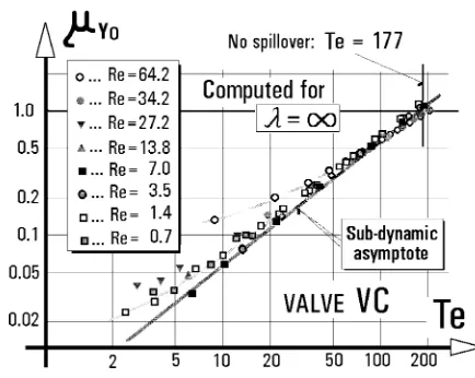
To get a useful output flow in the absence of dynamic effects, in the subdynamic regime the fluid may be driven by some unusual newly introduced phenomena, such as, e.g., electro-os-mosis. Generally easier (and necessary in the case of gas and nonpolar fluids) is to remain on the classical fluid mechanical side and drive the flow through by an applied pressure differ-ence. This is the pressure-assisted [8] or even pressure-driven mode of operation. Initially as nothing more than just a useful tool for adjusting the driving pressure, a dimensionless pa-rameter Te was introduced [6]. It was later shown to exhibit a number of interesting interpretations [9], [16], [17]. Currently, most microfluidic devices are not operated in the truly subdy-namic regime. Nevertheless, it represents a useful limiting case with which the device behavior may be compared. In partic-ular, the relations derived for the subdynamic flow, utilizing the characteristic constancy (independence on Re) tend to be simple and may provide a useful reference and design tool.
III. MICROFLUIDICVALVEEXAMPLES
Mutually supporting information is now available from the development of a number of microfluidic valves, sufficiently convincing to permit the formulation of general qualitative conclusions beyond reasonable doubts—despite the difficul-ties associated with investigating the subdynamic regime in microfluidic valves experimentally. The valves were of planar configuration, made by etching in thin stainless steel laminates. The etching process was performed by a professional sup-plier (Microponents Ltd., Birmingham, U.K.). Both one sided etching and etching from both sides (in which case the effect of increased cavity depth could be investigated by stacking the laminates) were used. Some devices were also investigated ex-perimentally on scaled-up (5 or 10 ) laboratory models, made by laser cutting in polymethylmethacrylate. Most experiments were performed with air as the working fluid. Pressure differ-ences were measured by liquid-filled U-tube or inclined-arm manometers. The small flow rates were measured by timing the motion of an air bubble in calibrated horizontal liquid-filled sections of the supply tubes.
TESA ˇRet al.: SUBDYNAMIC ASYMPTOTIC BEHAVIOR OF MICROFLUIDIC VALVES 337
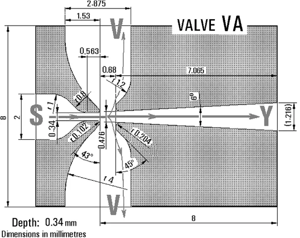
Fig. 1. Fluidic passive flow control valveVA. At large Reynolds numbers the output flow in Y is larger than supply flow from S due to jet pumping entrainment from the vents V. At low Re the entrainment effect is overcome by spilling fluid over into V.
correspondence with the experimental data requires at least 8 grid elements across the depth of the cavities. There were only a few cases of significant disagreement (an example shown here in one of the accompanying diagrams), which could be traced to such effects as shedding and repeated formation of a vortex which the steady-state computations predicted to be stationary [13].
A. Spillover Valve
This no-moving-part valve is shown in Fig. 1. It is a rather special passive flow control valve, possessing no control inlet. Its operation is based upon using the Reynolds number depen-dence of its output flow rate. At high Reynolds numbers this device can operate as an effective jet-pumping passive flow am-plifier, increasing the flow passing through it by entraining into the jet additional fluid from the two vents V. Although this valve is not very small (nozzle width ), it is operated in the typical microfluidic low Re region (around ) because of the high viscosity of the hot “syngas” working fluid (gas for fuel synthesis, containing a large proportion of high viscosity hydrogen) and small flow rates. At these conditions the collector channel, despite its gradual expansion in the downstream direc-tion, ceases to produce a diffuser effect and the dominant effect is the viscous resistance in the output flowpath. This causes fluid to spill over into the vents rather than entraining it. The depen-dence of the spillover flow on Re is due to the varying blockage of the vent flows by the varying size of the recirculation regions (Fig. 2—in fact the same vortices as observed e.g. in the low Re impinging jet flows [21]). As shown in Fig. 3, the size of the recirculation regions and their blocking action become less effective as Re decreases. This is reflected in Fig. 4 by the de-creasing relative output flow rate
(1)
Fig. 2. Computed pathlines in the valveVAin a typical low Re regime.
[image:4.594.342.509.349.541.2]Fig. 3. Decreasing size of the recirculation region in valve VA with decreasing Re. At Reynolds numbers of the orderRe 1asymptotic state is reached in which the pathline pattern ceases to depend upon Re.
Fig. 4. Dependence of relative output flow on Reynolds number for the valveVA.
B. Flow Interrupting Valve
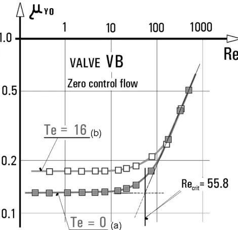
An example of such situation was encountered while in-vestigating the flows in individual components of another no-moving-part valve, shown in Fig. 5. Although seemingly similar to the valve from Fig. 1, this valve was designed for a different flow control mode: active control by the flow admitted to the control terminal X. The valve was developed [16] to form a part of an integrated circuit in microchemical application (fuel synthesis catalyst testing) where its task is to interrupt the flow of a hot gas sample into a composition analyzer by diverting it into the vent (see Fig. 6). It is also operated in the typical microfluidic regime (about ), where the dependence of the relative output flow in the zero control flow state on Re in Fig. 7 shows the available output flow to be only a small percentage of that supplied by the flow generator. Despite the fluid acceleration in the supply nozzle, the inertia of the jet opposed by the strong viscous friction does not suffice for transferring the fluid efficiently into the collector. The valve has to be therefore operated as pressure assisted. The
flow into the load is facilitated by applying a constant pressure difference between the vent V and the output terminal Y. This assisting pressure, in nondimensionalised form as the parameter Te, is seen in Fig. 7 to increase the value of the critical Reynolds number (by lifting the horizontal line of the subdynamic regime while the sloping dynamic regime B is little affected, at least in the logarithmic coordinates used for locating as the intersection the extrapolated straight lines).
The magnitude of the driving pressure difference , which at low Re clearly becomes the decisive factor, has to be adjusted quite carefully. As a useful tool for the adjustment, a dimensionless parameter Te was introduced in [6], [8] and [9], defined
(2)
relating the driving pressure difference to the supply flow rate (the other quantities are defined in the Nomen-clature). Note that because of the usual convention of relating pressure in device terminals to the vent pressure , the driving
pressure is negative—this is the reason for
the absolute value in the definition. Obviously, Fig. 7 shows the value to be too small for bringing really useful improvement; in fact, the valve is actually operated at about
.
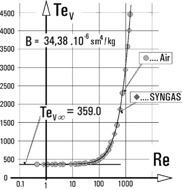
There are several interesting interpretations of the physical meaning of the parameter Te—as will be shown in the next part of the present paper. One of them is its being the ratio of pressure forces to inertial forces acting on a fluid element. This becomes rather simple in the case of fluidic devices having only two ter-minals, where Te is shown to represent the nondimensionalised value of their fluidic resistance. This interpretation is useful in investigations of aerodynamic properties of individual compo-nents of the valves—such as their supply nozzle, vent channel, or output channel. Such investigations were performed for the valve and examples of the results are shown in Fig. 8 (flu-idic resistance of the vent) and Fig. 9 (flu(flu-idic resistance of the output channel) plotted as a function of Reynolds number. Flu-idic resistance as defined as the proportionality constant in the assumed linear dependence
(3)
between the pressure drop across the device and the volume flow rate passing through it. This direct analogy to the Ohm’s law of electric circuits assumes incompressible flow conditions, rarely a real problem. The reason for small popularity of the resistance concepts in fluidics—as opposed to its universal acceptance in electronics—are
a) nonlinearity, usually hardly avoidable in fluidics; b) dependence upon fluid properties and state.
The latter problem is removed by converting the resistance values into the presentation by means of Te, as is documented in Fig. 10.
[image:5.594.48.284.309.482.2]TESA ˇRet al.: SUBDYNAMIC ASYMPTOTIC BEHAVIOR OF MICROFLUIDIC VALVES 339
Fig. 5. Active flow control valveVB—ref. [6]. Control flow admitted to X sweeps away into the vent V the fluid supplied from S, thus preventing it from reaching the output Y.
Fig. 6. Typical application of the valveVBplaced between the supply loop (constant flow supplied by the generator) and the loop with the load in which the flow is controlled.
becomes not independent of Reynolds number—despite the ab-sence of vortices (especially apparent in the collector flow be-tween locations A and B in Fig. 9) that might cause the disap-pearance of the Re dependence in Fig. 3.
C. Flow Interrupting Valve With Inclined Powerful Control Jet
[image:6.594.40.287.480.648.2]Fig. 7. Two dependences of the relative output flow at zero control flow on Reynolds number for the valveVB: (a) for zero driving pressure Te=0 and (b) for small driving pressure, nondimensionalized by means of the parameter Te=16.
the data available in [6] and [8] show also the transition into the subdynamic regime with loss of dependence upon Re.
D. Valve With Jet-Pump Cleansing of Downstream Cavities
Another related valve, designed by Tippetts, is the very spe-cial example shown in Fig. 12. An array of these valves forms the basic part of the sampling unit [10] for selecting a sample from several microreactors to be delivered into an analyzer [14]. The special features are due to the requirements: 1) to propelall
[image:7.594.304.551.63.482.2]of the control flow to V despite the adverse pressure drop from V to Y, 2) to reverse the flow at Y by entraining a small purge flow to clear previous sample remnant from stagnant zones in the flow path to the analyzer, and 3) to decouple S from the ef-fects of control flow so that it is influenced only by the ideally constant pressure at V (not the dynamic pressure of the control flow). The high Reynolds number control flow approach, analo-gous to the case above, is used and the output flow reversal is achieved by employing the jet-pumping effect generated by the powerful control jet. To facilitate the effect, the valve part between the control inlet and the vent is shaped as a clas-sical jet pump (with one-sided suction port—note the similarity of this part and the valve which at high Re is also a jet pump, but with suction ports on both sides). The properties were inves-tigated, as presented in [14], by three coordinated approaches. Apart from experimental measurements of the characteristics, the internal flowfield was studied using flow visualization in a scaled-up laboratory model as well as by the usual steady-state numerical CFD solutions. The latter two approaches in fact ini-tially exhibited a systematic disagreement [13], the explanation of which (by vortex shedding unsteadiness, not accounted for by the original steady state computations) in the end helped to a better understanding of the processes that takes place there. The valve is designed for operation in the pressure driven mode: note
Fig. 8. Fluidic resistance of the vent path (between A and B) in the valveVB. Note the difference in values obtained for synthetization gas (mixture ofH and CO to be used in the actual application) and air (used in laboratory tests).
the absence of any nozzle contraction in the channel leading from the supply terminal S and also the absence of any diffuser in the collector channel leading to Y.
IV. THECRITICALREYNOLDSNUMBER
In all cases studied so far, the decreasing Re was found to lead into the subdynamic regime, characterized by independence of the characterising ratios on Reynolds number—as shown in Figs. 4, 7, 13, and the analogous diagram for the valve presented in [6]. In fact, also the constant resistances in the low Re limit, as shown in Figs. 8, 9, and 10, fall into this category. It should be stressed again that variables like velocity or pressure continue to decrease in this regime with decreasing Re—so that this is by no means a result of a decreased sensitivity of experimental or numerical procedures. It is only the ratios of the quantities that exhibit the self-similarity.
TESA ˇRet al.: SUBDYNAMIC ASYMPTOTIC BEHAVIOR OF MICROFLUIDIC VALVES 341
Fig. 9. Fluidic resistance of the collector path of the valveVB(between A and B, the upstream inlet added for flow regularization in A). The desirable constant resistance value is obtained only in the subdynamic limit.
Fig. 10. Resistance of the vent from Fig. 8 expressed by means of the parameter Te: a single universal curve valid for any fluid (and, though not demonstrated here, also for any size).
[image:8.594.40.284.66.346.2]the valves would be rather useless for practical flow control pur-poses. The small available output flow provides no opportunity for the control effect that would decrease it further. The phenom-enon is, nevertheless, interesting from theoretical point of view. The existence of the Re-independent self-similar regime entered through a distinct transition is contrary to common expectations. The governing equations certainly do not suggest any physical reason for such an essential change in the character of the flow. Yet the regime is there and the transition into it is quite abrupt and well defined, especially in cases with the local minima as
[image:8.594.331.521.315.467.2]Fig. 11. Microfluidic valve VC with active flow control by an inclined powerful jet, preventing the main flow supplied into S from reaching the output Y.
Fig. 12. Pressure driven microfluidic valveVDfor very large control flow and jet pumping effect in the CLOSED state [14].
shown in Fig. 13, so that it cannot be dismissed as perhaps an artefact caused by the logarithmic coordinates.
The minimum in Fig. 13 is associated with the departure from the standard placement of the collector directly opposite to the nozzle as used in large-scale fluidics. This standard layout is re-tained in the configurations VA (see Fig. 1), VB (see Fig. 5), and VC (see Fig. 11) and is characterized by a smooth rise of due to the increasing importance of fluid inertia when Re is increased from the subdynamic regime. On the other hand, in the purely pressure-driven valve VD (see Fig. 12) the supply and collector channels (there is no real supply nozzle) do not even lie on the same straight line so that capturing any accelerated fluid by the collector after the tortuous way between them is difficult. In fact the fluid is offered a much easier way out from the valve through the vent V (see Fig. 12) and this causes an initial de-crease of caused by fluid inertia when Re is increased from the subdynamic regime.
[image:8.594.71.255.397.589.2]Fig. 13. Relative output flow at zero control flow for the valveVDat low Reynolds numbers improves substantially with increasing driving pressure (nondimensionalised by Te). The particularly pronounced transition into the subdynamic regime is due to the complicated main flow path from S to Y.
Fig. 14. The effect of cavity depth in the valve VAon the efficiency of fluid transfer from the nozzle into the output (no pressure driving effect). With increasing aspect ratio = h=bthe efficiency increases in the regime B, but decreases in the subdynamic regime. As a result, the criticalRe decreases.
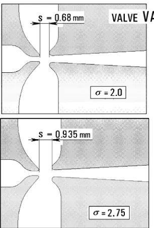
Fig. 7 for the short and straight path from the nozzle exit to the collector of the valve from Fig. 5 does not suggest a simple de-pendence on the ease of entry into the output. Until now, only a few studies have tried to get more information about this depen-dence by evaluating for otherwise identical valves that differ in only selected design details or dimensions. Obviously, does not depend only on the “groundplan” shape of the cavities. The value decreases if—for an identical cavity shape—an increasing depth h causes less friction on the bottom and top plate. This is demonstrated by the lower found in Fig. 14 when increasing the nozzle aspect ratio (where b is the nozzle exit channel width) of the constant-depth planar design VA from Fig. 1. On the other hand, the decreasing sepa-ration distance s from the nozzle to the collector in Fig. 15 may suggest a higher due easier entry into the collector—but this applies both in the subdynamic regime as well as in the dy-namic laminar regime B so that the position of the intersection point in Fig. 16 is not affected significantly.
[image:9.594.67.270.329.476.2]Fig. 15. Investigated effect of the separation distance S between the nozzle and the collector—valveVA.
Fig. 16. Not unexpectedly, the effectiveness of nozzle-to-collector fluid transfer decreases both in the regime B as well as the subdynamic regime with increasing nondimensional separation distance = s=b(Fig. 15). There is no significant change in the critical Re.
V. CHARACTERIZATION OFTWO-TERMINALDEVICES
By contrast with its definition in (2) introduced in [8] for mul-titerminal valves, where the dimensionless parameter Te is eval-uated from mutually independent flow and pressure drop, the parameter becomes an easily tractable quantity for two-terminal devices. It can then be evaluated from the ratio of pressure drop across and flow through the same channel—and this means it is simply proportional to the value of the fluidic resistance R
as defined in (3)
(4)
—with proportionality constant
[image:9.594.326.530.339.499.2]TESA ˇRet al.: SUBDYNAMIC ASYMPTOTIC BEHAVIOR OF MICROFLUIDIC VALVES 343
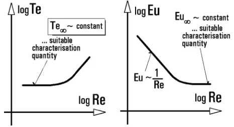
Fig. 17. The role of the pressure parameter Te as the asymptotic reference at low Re is analogical to that of the Euler number (loss coefficient) at high Re.
It should be noted that the definitions (2) and (3) are valid for incompressible flow—this admits the use of the volume flow rate as the through variable. While compressibility is usually not a problem, there are other factors that have hindered the ap-plicability of fluidic resistance R, making it less useful than the ohmic resistance in electric circuits, which is commonly used to characterize properties of elements in steady state. The first problem is fluidic resistance R being not just a property of a particular device, as it depends on fluid properties. Not only do the values differ when using a different fluid, but even with the same fluid they vary with its state (e.g., with its temperature). The second reason for the unpopularity of the resistance con-cept in large-scale fluidics has been its inconstancy even for the same device and for the same fluid due to the fact that fluid flows are not governed by an analogue of the linear Ohm’s law. Even in laminar flow there are quadratic dynamic loss components that cause deviations from linearity.
It is only in the subdynamic asymptotic limit where all dynamic effects—and the deviations from linearity they cause—disappear completely. Use of the nondimensional representation by Te then removes also the other problem, the dependence upon properties and state of the fluid. Thus the asymptotic subdynamic value of the parameter, , may be considered the sought-after characterization quantity for two-terminal devices in microfluidics. It is the counterpart to the analogous Euler number Eu for large-scale two-terminal devices (- more exactly, the asymptotic value for the other asymptotic limit ) as shown in Fig. 17.
As for the physical meaning of the parameter Te, we may con-sider a fluid element in the form of a cube of side length (= the characteristic dimension). A positive velocity , evalu-ated from volume from rate by dividing it by the characteristic cross-sectional area, leads to negative pressure drop (pres-sure decreasing in downstream direction). The pres(pres-sure force acting on the fluid element is
(6)
(pressure difference multiplication by the cube side area). Lam-inar friction is governed by the Newton’s law: the characteristic shear stress is proportional to the velocity gradient
(7)
The viscous friction force acting on the cube is evaluated as this shear stress multiplied by the characteristic area
(8)
Comparison of the expressions (6) and (8) shows that Te is the ratio of the two forces:
(9)
VI. ASYMPTOTICZERO-DIMENSIONALMODELS
Behavior of high Re fluidic valves (and other more complex) devices is mostly determined by the dynamic effects arising in mutual interaction of the flows. The channels (nozzles, collec-tors) connecting the interaction cavity with the device terminals generate the necessary conversions between the component of fluid energy (pressure to kinetic in a nozzle and back in a dif-fuser), but generally do not have much influence on the overall energetic budget—in particular the vents, wide and short, gen-erate an almost insignificant energy drop.
This is changed substantially as the subdynamic regime is ap-proached. The dynamic effects become insignificant and the de-vice properties become determined by hydraulic loss properties the channels, the pressure differences across which increase dra-matically. In the limit of the subdynamic regime it becomes fully justified to evaluate the device properties by the linear zero-di-mensional models consisting of linear resistors. The starting point in this analysis is the evaluation of the resistances that characterize the individual valve components (channels). For the investigations of the output flow discussed here, it is suf-ficient to know only the resistances of the two channels through which the fluid may exit: the output collector and the vent. The usually long and narrow collector is a typical example of a com-ponent having a bad reputation in fluidics as being not easily characterized by the usual quadratic characterization using the Euler number. The large friction component of the loss causes deviations from the assumed quadraticity. This means the con-ditions are far from the asymptotic limit . Usual oper-ating conditions of microfluidics may be similarly far from the other limit assumed in the linear asymptotic character-ization of the subdynamic regime, but because of the substan-tially increased importance of the collector properties for the overall behavior, the linear asymptotic solutions may provide a useful information.
For example, the behavior of the valve at low Re may be usefully investigated using equivalent circuit models built of linear restrictors characterized by the asymptotic values of the resistances, which for the collector when operated with air has value
(10)
and for the vent when operated with air
Fig. 18. Equivalent restriior circuit for Inear analysis of the relative output flow relying upon dynamic action of the supply (jet) flow.
To eliminate the problems caused by the inlet conditions, while the resistance values were evaluated between the inter-rogation plane locations and , the investigations incorpo-rated an additional inlet part: the nozzle contraction generating flow conditions approximating those of the real operation of the component.
A. Relative Output Flow—No Driving Pressure, No Control Flow
In the subdynamic regime the relative output flow as-sumes a value independent of Re, but determined solely by the resistances of the two available exit paths from the valve, Fig. 18. In an unloaded valve, the total supplied flow is divided into
(12)
while the output flow rate is
(13)
so that their ratio (1) depends only on the ratio
(14)
of the corresponding parameters (related to the same refer-ence value B)
(15)
In the case of the valve , the ratio of the asymptotic values of the pressure parameters is
(16)
so that the asymptotic value of the relative output flow in the subdynamic domain should be
(17)
[image:11.594.349.508.68.191.2]This is in excellent agreement with the numerical flowfield com-putation results for zero driving pressure in Fig. 7. The value, of course, is too small for most practical applications (where the
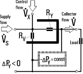
Fig. 19. Equivalent restrictor circuit for evaluating the zero-control relative output flow in a microfluidic valve driven by the constant pressure difference between valve output terminal Y and vent V.
[image:11.594.302.529.258.461.2]Fig. 20. Relative output flow at zero control flow computed by numerical flowfield solutions and plotted as a function of the pressure parameter Te for the valveVBat a very low Reynolds number is in agreement with the prediction of asymptotic linear analysis.
[image:11.594.316.533.550.723.2]TESA ˇRet al.: SUBDYNAMIC ASYMPTOTIC BEHAVIOR OF MICROFLUIDIC VALVES 345
Fig. 22. Numerical flowfield computations of the relative output flow for the valveVDat zero control flow compared with the asymptotic analysis of equivalent resistances and laboratory experiments using different fluids (including water—made possible by the similarity provided by the parameter Te).
output flow would be further decreased by the resistance of the load).
B. Relative Output Flow—The Effect of the Driving Pressure at Zero Control Flow
An improvement in the behavior is obtained by applying the driving pressure , (maintained by an external pres-sure regulator, usually no problem in the context of MEMS with electronic control circuits available often on the same chip). The equivalent circuit in Fig. 19, again assuming no interaction be-tween the flows upstream from the restrictors and no connected load, yields the condition for the pressure differences
(18)
so that by rearranging and dividing by the sum of the resistances
(19)
The ratio in the second term, of course, is the same as in the definition of Te in (2), while the first term may be simplified using (14)
(20)
This initial constant value (intercept) plus linear growth is found again to be in excellent agreement with the values evaluated from numerical flowfield computations, as shown in Fig. 20 for the valve at very low, subdynamic Re. In Figs. 21 and 22, the straight line (20) is seen to represent the asymptote ap-proached by the values computed and experimentally found for larger, supercritical Re.
Fig. 23. Equivalent circuit for evaluating the flow transfer characteristic of a microfluidic valve driven by the constant pressure difference.
Application of the driving pressure can lead to any desired value of , even to the often desirable no-spillover condition in which no fluid leaves through the vent. The analysis for the subdynamic limit provides a way for determining the corresponding no-spillover value of Te and is thus extremely useful for adjustment of the pressure conditions in the fluidic circuit even at Reynolds numbers far above the critical .
C. Flow Transfer Characteristics
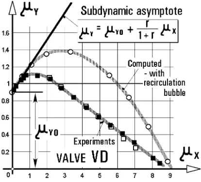
[image:12.594.358.496.358.482.2]Fig. 24. Flow transfer characteristic of the pressure-driven valveVD(see Fig. 12): experiment, computation, and asymptotic analysis for the subdynamic regime in which output flow increases as the small control flow is initially simply added to the supplied flow.
is possible to evaluate the initial slope of the flow transfer char-acteristic in relative coordinates: the dependence of the output flow on the input flow rate
(21)
The analysis begins with the pressure drop condition similar to (18) taking into account the control flow
(22)
This may be rearranges as
(23)
and using the expression from (19):
(24)
Data evaluated for the investigated valves agree with this pre-diction of the subdynamic theory. An example is presented in Fig. 24 for the valve , which also gives an indication of the large control flow required for decreasing the output flow. To get zero output flow requires according to Fig. 24 a control flow 9-times as large as the supplied main flow (valid for particular conditions discussed in more detail in [16]). Such large control flows are needed to get into the safe realm of the dynamic flow phenomena.
VII. CONCLUSION
Principles of no-moving part fluidics dependent upon fluid in-ertia cease to be applicable at extremely low Reynolds numbers, where design of flow control valves meets new challenges and calls for new approaches. The subject of the present paper is an
approach based upon use of flow assisting and even flow driving pressure difference.
The scientific approach to any problem, at least in mechan-ical sciences, should concentrate on seeking the invariants of the problem—cf., e.g., [19]. From this perspective, the identifica-tion of the self-similar subdynamic flow regime with auto-mod-eling properties in fluidic flow control devices may be of basic importance. The paper discusses examples of recently devel-oped pressure driven microfluidic valves and shows how, de-spite their operating regime being at higher Re values, outside the subdynamic regime, it provides a useful asymptotic limits for performance evaluation and prediction.
REFERENCES
[1] H. A. Stone and S. Kim, “Microfluidics: basic issues, applications, and challenges,”AIChE J., vol. 47, no. 6, p. 1250, June 2001.
[2] W. Ehrfeld, Ed., Microreaction Technology: Industrial Prospects. Berlin, Germany: Springer-Verlag, 2000.
[3] O. M. Wilkinet al., “High throughput testing of catalysts for the hy-drogenation of carbon monoxide to ethanol,” inPrinciples and Methods for Accelerated Catalyst Design and Testing, E. G. Derouanneet al., Eds. New York: Kluwer, 2002, pp. 299–303.
[4] V. Tesaˇr, “Valvole fluidiche senza parti mobili,” Oleodinamica—pneu-matica, vol. 39, no. 3, p. 216, 1998.
[5] V. Tesaˇr, R. W. K. Allen, and J. R. Tippetts, “Microfluidics—the chal-lenge of low Re flow control,” inFLUCOME 2000, Proc. of 6th Tri-ennial Int. Symp. on Fluid Control, Measurement and Visualization, A. Lanneville, Ed., Sherbrooke, Canada, Aug. 2000, Paper 052.
[6] V. Tesaˇr, “Microfluidic valves for flow control at low Reynolds num-bers,”J. Visualization, vol. 4, no. 1, pp. 51–60, 2001.
[7] G. H. Priestman and J. R. Tippetts, “Development and potential of power fluidics for process flow control,”Chem. Eng. Res. Design, vol. 62, no. 2, p. 67, 1984.
[8] V. Tesaˇr, “Asymptotic correlation for pressure-assisted jet-type microflu-idic devices,” inProc. “Topical Problems of Fluid Mechanics 2000”. Prague, Czech Republic, Feb. 2000, pp. 85–88.
[9] , “Subdynamic behavior of pressure-driven microfluidic valves,” in Proc. 7th Triennial International Symposium on Fluid Control, Mea-surement and Visualization FLUCOME ’03, G. M. Carlomagno and I. Grant, Eds., Sorrento, Italy, August 2003, Paper no. 192.
[10] , “Sampling by fluidics and microfluidics,”Acta Polytechnica—J. Adv. Eng., vol. 42, no. 2, pp. 41–49, 2002.
[11] , “Microfluidic turn-down valve,”Journal of Visualization, vol. 5, no. 3, pp. 301–307, 2002.
[12] , Microfluidics. Bad Mergentheim, Germany: Umwelt- und Fluid-Technik, Jun. 2002, pp. 97–114.
[13] V. Tesaˇr, J. R. Tippetts, and R. W. K. Allen, “Failure’ of steady CFD solutions caused by vortex shedding,” inDevelopments in Machinery Design and Control, K. Peszynski, Ed. Bydgoszcz, Poland, 2004. [14] V. Tesaˇret al., “Development of a microfluidic unit for sequencing fluid
samples for composition analysis,”Chemical Engineering Research and Design, Trans. of the Inst. of Chem. Engrs, pt. A, vol. 82, no. A6, June 2004.
[15] V. Tesaˇr, “Fluid plug’ microfluidic valve for low Reynolds number fluid flow selector units,”J. Visualization, vol. 6, no. 1, pp. 77–85, 2003. [16] , “Subdynamické asymptotické chování mikrofluidického ventilu,”
Automatizace, no. 12, December 2002.
[17] , “New fluid flow parameter—its meaning and importance, in par-ticular for microfluidics,” inDevelopments in Control and Machinery Design, J. Sempruch, Ed. Bydgoszcz, Poland, 2003.
[18] , “Großmaßstäbliche fluidische Ventile für die Durchflußs-teuerung,” . Berlin, Germany: Messen-steuern-regeln, 1983, vol. 26. [19] N. K. Ibragimov,Elementary Lie Group Analysis and Ordinary
Differ-ential Equations. New York: Wiley, 1999.
[20] N.-T. Nguyen and S. Wereley,Fundamentals and Applications of Mi-crofluidics. Norwood, MA: Artech House, 2002.
TESA ˇRet al.: SUBDYNAMIC ASYMPTOTIC BEHAVIOR OF MICROFLUIDIC VALVES 347
Václav Tesaˇrwas born in 1939 in Prague, Czech Republic. He received the M.Sc. degree in me-chanical engineering in 1963 from ˇCVUT—Czech Technical University, Praha, Czech Republic, where he was then employed up to 1999. He received the equivalent of a Ph.D. degree from ˇCVUT Praha in 1972.
From 1994 to 1998, he was the Head of the De-partment of Fluid Mechanics and Thermodynamics. Since 1999, he has been a member of the Process Fluidics Group, Department of Chemical and Process Engineering, the University of Sheffield, U.K. His research interests cover fluid mechanics in general, mainly flow visualization and study of turbulence, and concentrate on studies of jets and wall jets, including their applications in the no-moving-part fluidics and microfluidics. He is named as the inventor on 195 Czech Patents, mainly covering fluidic devices.
John R. TippettsWas born in 1943 in Birmingham, U.K. He received the B.Sc.Eng. degree in mechanical engineering from the University of Southampton and the Ph.D. degree from the University of Sheffield.
In 1969, he became a Research Fellow in the Mechanical Engineering Department working with a team headed by Professor J. K. Royle on fluidics and electro-rheological fluids. Later, he moved to the Department of Chemical and Process Engineering, becoming a Senior Research Fellow working on combustion aerodynamics, fluidics, and multiphase flows. In May 2004, he became an independent consultant with continuing work at the university, and with industry concerning no-moving-part flow control in which he is an internationally acknowledged expert. His particular achievement has been development of the whole area of fluidic pumping, mainly applied to handling dangerous fluids in nuclear fuel reprocessing.
Ray W. K. Allenwas born in 1948 in Hampshire, U.K., and received the Undergraduate degree in chemical engineering from the University of Man-chester, U.K. This was followed by a Master’s degree from University of Manchester and the Ph.D. from McGill University, Montreal, QC, Canada.
He worked at the Harwell Laboratory until 1995 when he came to Sheffield and was Head of the newly formed Department of Chemical and Process Engineering until August 2000, while also working at DTI’s Innovation Unit. His research interests began with environmental engineering, particularly design of gas cleaning plant and now straddle microfluidics, chemical reaction engineering and hydrogen production via thermochemical cycles. The focus of such work is the chemistry/chemical engineering interface applied to developing novel designs of reactors involving microfluidics. He is Chairman of the U.K. Standing Conference of Professors and Heads of Department of Chemical Engineering and a member of the Committee of the Engineering Professors’ Council of the U.K.
Yee Y. Lowwas born in Kuala Lumpur, Malaysia, in 1976. She received the diploma in chemical engi-neering in Prime College, Malaysia, and then joined the Department of Chemical and Process Engineering at the University of Sheffield to pursue her undergrad-uate studies. She received the B.Eng. degree (First Class Honors) in chemical and process engineering with fuel technology. She received the Ph.D. degree in 2003.

![Fig. 5.Active flow control valve VB—ref. [6]. Control flow admitted to X sweeps away into the vent V the fluid supplied from S, thus preventing it fromreaching the output Y.](https://thumb-us.123doks.com/thumbv2/123dok_us/8089147.231017/6.594.40.287.480.648/active-control-control-admitted-sweeps-supplied-preventing-fromreaching.webp)