Thesis submitted in accordance with the requirements of the University of Liverpool for the degree of Doctor in Philosophy
by
Yufei Jiang
In this thesis, a number of semi-blind structures are proposed for Orthogonal Frequency
Division Multiplexing (OFDM) based wireless communication systems, with Carrier
Frequency Offset (CFO) estimation and Independent Component Analysis (ICA) based
equalization.
In the first contribution, a semi-blind non-redundant single-user Multiple-Input
Multiple-Output (MIMO) OFDM system is proposed, with a precoding aided CFO
estimation approach and an ICA based equalization structure. A number of reference
data sequences are carefully designed and selected from a pool of orthogonal sequences,
killing two birds with one stone. On the one hand, the precoding based CFO estimation
is performed by minimizing the sum cross-correlations between the CFO compensated
signals and the rest of the orthogonal sequences in the pool. On the other hand, the
same reference data sequences enable the elimination of permutation and quadrant
ambiguities in the ICA equalized signals. Simulation results show that the proposed
semi-blind MIMO OFDM system can achieve a Bit Error Rate (BER) performance
close to the ideal case with perfect Channel State Information (CSI) and no CFO.
In the second contribution, a low-complexity semi-blind structure, with a
multi-CFO estimation method and an ICA based equalization scheme, is proposed for
mul-tiuser Coordinated Multi-Point (CoMP) OFDM systems. A short pilot is carefully
designed offline for each user and has a two-fold advantage. On the one hand, using
the pilot structure, a complex multi-dimensional search for multiple CFOs is divided
signals. Simulation results show that the proposed semi-blind CoMP OFDM system
can provide a BER performance close to the ideal case with perfect CSI and no CFO.
In the third contribution, a semi-blind structure is proposed for Carrier Aggregation
(CA) based CoMP Orthogonal Frequency Division Multiple Access (OFDMA) systems,
with an ICA based joint Inter-Carrier Interference (ICI) mitigation and equalization
scheme. The CFO-induced ICI is mitigated implicitly via ICA based equalization,
with-out introducing feedback overhead for CFO correction. The permutation and quadrant
ambiguities in the ICA equalized signals can be eliminated by a small number of pilots.
Simulation results show that with a low training overhead, the proposed semi-blind
equalization scheme can provide a BER performance close to the ideal case with
Abstract i
Contents vi
Acknowledgements x
List of Figures x
List of Tables x
Acronyms xi
List of Symbols xv
1 Introduction 1
1.1 Background . . . 1
1.2 Research Contributions . . . 3
1.3 Thesis Organization . . . 5
1.4 List of Publications . . . 6
2 Wireless Communication Channels and Systems 9 2.1 Wireless Communication Channels . . . 9
2.1.1 Propagation Mechanisms . . . 9
2.1.2 Large-Scale Radio Propagation . . . 10
2.2.1 OFDM Technology . . . 18
2.2.2 MIMO OFDM Systems . . . 26
2.2.3 CoMP Transmission . . . 31
2.2.4 CA Technology . . . 33
3 Literature Review 37 3.1 CFO Estimation . . . 37
3.1.1 Preamble based CFO Estimation . . . 37
3.1.2 Blind and Semi-Blind CFO Estimation . . . 41
3.2 Channel Estimation and Equalization . . . 44
3.2.1 Training based Channel Estimation and Equalization . . . 44
3.2.2 Blind or Semi-Blind Equalization . . . 49
4 Semi-Blind CFO Estimation and Equalization for Single-User MIMO OFDM Systems 56 4.1 Introduction . . . 56
4.2 System Model . . . 58
4.3 Precoding Design . . . 59
4.3.1 Precoding . . . 59
4.3.2 Reference Data Design . . . 60
4.3.3 Discussion of Precoding Constant . . . 62
4.4 Precoding based Semi-Blind CFO Estimation . . . 62
4.5 Precoding aided Semi-Blind ICA based Equalization . . . 65
4.5.1 ICA based Equalization . . . 65
4.5.2 Ambiguity Elimination . . . 66
4.6 Complexity Analysis . . . 67
4.8 Summary . . . 71
5 Semi-Blind Multi-CFO Estimation and Equalization for Multiuser CoMP OFDM Systems 73 5.1 Introduction . . . 73
5.2 System Model . . . 76
5.3 Pilot Design . . . 77
5.3.1 Semi-Orthogonal Pilot . . . 77
5.3.2 Requirement on Pilot Length . . . 79
5.4 SOP based Multi-CFO Estimation . . . 79
5.4.1 Multi-CFO Separation . . . 80
5.4.2 Multi-CFO Estimation . . . 80
5.4.3 Carrier Frequency Adjustments . . . 81
5.5 ICA based Equalization . . . 82
5.5.1 Phase Correction . . . 83
5.5.2 Permutation and Quadrant Ambiguities Elimination . . . 83
5.6 Complexity Analysis . . . 84
5.7 Simulation Results . . . 85
5.8 Summary . . . 91
6 Semi-Blind Joint ICI Mitigation and Equalization for CA based CoMP OFDMA Systems 94 6.1 Introduction . . . 94
6.2 System Model . . . 96
6.3 ICA based Equalization and ICI Mitigation . . . 101
6.3.1 ICA based Equalization . . . 101
6.3.2 Phase Correction . . . 102
6.4 Complexity Analysis . . . 106
6.5 Simulation Results . . . 107
6.6 Summary . . . 110
7 Conclusions and Future Work 112
7.1 Conclusions . . . 112
7.2 Future Work . . . 115
Appendix 118
A PROOF OF THEOREM 1 118
2.1 Indoor power delay profile . . . 13
2.2 Coherent bandwidth and signal bandwidth before and after OFDM . . . 19
2.3 CAS in OFDMA systems . . . 24
2.4 MIMO OFDM systems block diagram . . . 27
2.5 Convolution process of signal and channel for MIMO OFDM systems . . 29
2.6 Wireless CoMP system model with K users andM BSs . . . 32
2.7 Intra-band contiguous CA . . . 34
2.8 Intra-band non-contiguous CA . . . 34
2.9 Inter-band non-contiguous CA . . . 34
2.10 Inter-band non-contiguous CA block diagram at the transmitter . . . . 35
4.1 MSE performance of the proposed semi-blind precoding based CFO es-timation for MIMO OFDM systems . . . 69
4.2 BER performance of semi-blind precoding aided CFO estimation method and ICA based equalization structure for MIMO OFDM systems, in comparison to the MMSE based equalization method with perfect CSI and no CFO (EQ: equalization) . . . 70
ICA based equalization structure, in comparison to the ZF and MMSE
based equalization with perfect CSI and no CFO, withK = 2 users and
M = 2 BSs (est.: estimation, CE: channel estimation, EQ: equalization) 87
5.3 MSE performance of the SOP based multi-CFO estimation method for
multiuser CoMP OFDM system, in comparison to CAZAC based and
Moorse’s CFO estimation approaches, with K= 2 users andM = 2 BSs 88
5.4 Impact of different sets of CFOs on the MSE performance of the SOP
based multi-CFO estimation method for multiuser CoMP OFDM
sys-tems, withP = 4 pilot blocks, K= 2 users and M = 2 BSs . . . 89
5.5 Impact of the frame length on the BER performances of ICA based
semi-blind equalization structures with SOP and precoding, and in the
absence of CFO, with K= 2 users and M = 2 BSs . . . 90
6.1 Block diagram of the CA-CoMP OFDMA system with semi-blind ICA
based receivers (EQ: equalization) . . . 97
6.2 Subblock allocation with Q= 4 subblocks and K = 2 users . . . 98
6.3 SIC diagram for CA based CoMP OFDMA systems . . . 104
6.4 BER performance of the ICA based joint equalization and ICI mitigation
structure for CA based CoMP OFDMA systems with multiple CFOs
(EQ: equalization) . . . 108
6.5 Impact of different CFOs sets on BER performance of the ICA based
equalization structure for CA based CoMP OFDMA systems (EQ:
equal-ization, CFO set I: (component carrier 1: [0.1 -0.1; -0.1 0.1], component
carrier 2: [0.1 0.1; -0.1 -0.1]), CFO set II: (component carrier 1: [0.5 -0.5;
2.1 Path Loss Exponent Values in Different Environments . . . 11
2.2 Typical RMS Delay Spread . . . 13
2.3 Summary of Fading Channels. . . 16
4.1 Analytical Computational Complexity . . . 68
5.1 Analytical Computational Complexity
(P: Pilot length, N: Number of subcarriers, K: Number of users, M:
Number of BSs, ∆: Step size for CFO search,Q: Number of subcarriers
for SOP design,D: Number of subcarriers considered for CFO search) . 85
First of all, I would like to express my gratitude for the academic supervision and
support, which I have received from Dr. Xu Zhu, Dr. Eng Gee Lim and Prof. Yi
Huang, during the period of my Ph.D. study. Without their patience and invaluable
comments in revising this thesis, I could not have completed the work for my Ph.D.
study.
I am grateful to Xi’an Jiaotong-Liverpool University and the University of Liverpool
for providing me a Ph.D. studentship and a living allowance. Their support allowed
me to complete my research.
I would like to thank Dr. Jingbo Gao whose knowledge is of great help, Dr. Nan
Zhou for inspiring discussions, Dr. Linhao Dong for sharing views, Dr. Shi Cheng for
his help with tricky LATEX problems, Dr. Yungang Zhang for his advice on programming
and Dr. Jie Ren for her constant encouragement. The academic discussions with them
have been invaluable throughout my research work.
I am also thankful to my classmates and colleagues for their help and support in
my Ph.D. life: Dr. Chun Zhao, Dr. Chili Li, Mr. Jieming Ma, Mr. Wenfei Zhu, Mr.
Boyuan Sun, Mr. Teng Ma, Mr. Jun Yin, Mr. Chaowei Liu, Mr. Qinyuan Qian,
Mr. Yanghao Wang and Mr. Yang Li. I want to thank them for creating a family-like
environment in the lab where I have been working.
Finally, my gratitude is dedicated to my parents for their carefulness and
5G Fifth Generation
AWGN Additive White Gaussian Noise
BER Bit Error Rate
BS Base Station
BSS Blind Source Separation
CA Carrier Aggregation
CAI Co-Antenna Interference
CAS Carrier Assignment Scheme
CAZAC Constant Amplitude Zero Auto-Correlation
CCI Co-Channel Interference
CFO Carrier Frequency Offset
CIR Channel Impulse Response
CMA Constant Modulus Algorithm
CoMP Coordinated Multi-Point
CSI Channel State Information
DCA Direct Conversion Architecture
DFT Discrete Fourier Transform
EVD Eigenvalue Decomposition
FA Finite Alphabet
FDE Frequency Domain Equalization
FDM Frequency Division Multiplexing
FFT Fast Fourier Transform
HOS Higher Order Statistics
i.i.d. Independent Identically Distributed
I/Q Inphase/Quadrature
IBI Inter-Block Interference
ICA Independent Component Analysis
ICI Inter-Carrier Interference
IDFT Inverse Discrete Fourier Transform
IFFT Inverse Fast Fourier Transform
ISI Inter-Symbol Interference
JADE Joint Approximate Diagonalization of
Eigen-matrices
LOS Line-of-Sight
LOs Local Oscillators
LS Least-Square
LTE Long Term Evolution
MIMO Multiple-Input Multiple-Output
ML Maximum Likelihood
MMSE Minimum Mean Square Error
MPP Modified Periodic Pilot
MSE Mean Square Error
MUI Multiple-User Interference
MUSIC Multiple Signal Classification
NLOS Non Line-of-Sight
OFDM Orthogonal Frequency Division Multiplexing
OFDMA Orthogonal Frequency Division Multiple
Ac-cess
OP Orthogonal Pilot
PCA Principal Component Analysis
PDF Probability Density Function
PDP Power Delay Profile
RMS Root Mean Square
SIC Successive Interference Cancellation
SIMO Single-Input Multiple-Output
SISO Single-Input Single-Output
SNR Signal-to-Noise Ratio
SOP Semi-Orthogonal Pilot
SOS Second Order Statistics
STO Symbol Time Offset
V-BLAST Vertical Bell Laboratories Layered
Space-Time
ZF Zero Forcing
(·)+ pseudo-inverse
I0(·) the modified Bessel function of the first kind
and zero order
LCP length of CP
=m{·} imaginary part of a complex
Ø empty set
<e{·} real part of a complex
bxc a largest integer less than or equal to scalarx
Hadamard product
circular subtraction
1N an N×N all-one matrix IN an N×N identity matrix ICP last LCP rows ofIN
E(·) expectation
diag{x} a diagonal matrix whose diagonal elements
are entries of vectorx
tr(·) trace of a matrix
Introduction
1.1
Background
The technologies of wireless communications have experienced a rapid growth over
the past two decades [1]. The demands of high-data-rate services allow amounts of
research activities carried out to promote a higher system capacity. To achieve the
purpose, a number of wireless communication systems have been proposed and used.
Multiple-Input Multiple-Output (MIMO) systems [2], which can employ multiple
trans-mit and receive antennas, offer considerable capacity improvement over Single-Input
Single-Output (SISO) systems. Coordinated Multi-Point (CoMP) transmission [3] can
effectively manage the interference between cells and improve cell-edge throughput, by
allowing each separated Base Station (BS) to jointly deal with multiple users’ signals.
Carrier Aggregation (CA) transmission [4] [5] can provide very high data rates, by
aggregating multiple component carriers for the concurrent transmission. So far, the
above techniques, have been chosen for the wireless local area networks IEEE 802.11
standards [6], and adopted by Long Term Evolution (LTE)-Advanced standards [7] [8].
Orthogonal Frequency Division Multiplexing (OFDM) technology, first proposed in
1960 [9], is robust against frequency selective fading, by dividing frequency selective
fading channels into a number of frequency flat fading channels. Due to the rapid
de-velopment of digital signal processing, this technology becomes practically possible and
from OFDM, can improve frequency diversity for users to transmit signals
simultane-ously, by using different subcarriers. So far, OFDM or OFDMA has been employed
in a range of wireless communication systems, such as MIMO OFDM systems, CoMP
OFDM systems and CA based CoMP OFDMA systems.
At the receiver, the reverse process is referred to as equalization [1], transforming
the received signals back into the transmitted signals. To perform equalization,
equal-izer coefficients are required. Usually, they can be obtained directly from Channel State
Information (CSI). Traditionally, training signals are commonly used in wireless
com-munication systems to estimate the CSI at the receiver. However, transmitting training
signals reduces spectral efficiency, especially in wireless communication systems which
have very scarce bandwidth resource. Blind or semi-blind channel estimation and
equal-ization methods [10] can obtain the CSI and recover the source data directly from the
structure and statistics of the received signals, without extra bandwidth and power
needed for training. As no or little prior information is available in advance at the
receiver, blind or semi-blind equalization approaches can improve spectral efficiency.
The aim of this work is to research a number of semi-blind wireless communication
systems over frequency selective channels.
Independent Component Analysis (ICA) [11], as an efficient Higher Order Statistics
(HOS) based Blind Source Separation (BSS) technique, can recover the source signals
by maximizing the non-Gaussianity of the observed signals. Compared to the Second
Order Statistics (SOS) based blind methods, ICA potentially reduces noise sensitivity,
since the fourth or higher order cumulants of the Gaussian noise are equal to zero. The
aim of ICA is to find statistically independent components from the received data. So
far, ICA has been applied to a range of fields, including separation of signals in audio
applications or brain imaging, the analysis of economic data and feature extraction [11].
The use of ICA has the benefit of not requiring the CSI to perform blind or semi-blind
However, OFDM based systems have several drawbacks. One of drawbacks is the
Carrier Frequency Offset (CFO) [12], caused by the unavoidable difference between
Local Oscillators (LOs) at the transmitter and receiver. The CFO destroys the
orthog-onality between OFDM subcarriers, and results in the Inter-Carrier Interference (ICI).
This effect incurs a significant degradation in Bit Error Rate (BER) performance, if not
estimated and compensated for correctly. In single-user MIMO OFDM systems, only
a single CFO exists between transmitter and receiver, while there are multiple CFOs
in multiuser CoMP OFDM systems. The application of CA allows multiple LOs to
be installed for the concurrent transmission. Thus, there are a large number of CFOs
in CA based CoMP OFDMA systems, resulting in challenging multi-CFO estimation
problems.
1.2
Research Contributions
To the best of authors’ knowledge, this is the first time that ICA has been applied for a
number of OFDM based wireless communication systems, with the effect of CFO. The
main contributions are summarized as follows:
• A semi-blind single-user MIMO OFDM system is proposed, with a precoding
aided CFO estimation method and an ICA based equalization structure. A
non-redundant linear precoding process is performed by superimposing a number of
reference data sequences on the source data sequences, without introducing any
extra total transmit power or spectral overhead. These reference data sequences
are carefully designed offline and selected from a pool of orthogonal sequences, to
have two purposes. On the one hand, the precoding based CFO estimation is
per-formed by minimizing the sum cross-correlations between the CFO compensated
signals and the rest of the orthogonal sequences in the pool. On the other hand,
equalized signals by maximizing the cross-correlation between the ICA equalized
signals and the reference signals. Simulation results show that the semi-blind
precoding based CFO estimation method outperforms other existing approaches
in terms of MSE performance. The proposed semi-blind precoding aided ICA
based MIMO OFDM systems can provide a BER performance close to the ideal
case with perfect CSI and no CFO.
• A low-complexity semi-blind structure, with a multi-CFO estimation method and
an ICA based equalization scheme, is proposed for multiuser CoMP OFDM
sys-tems. A short pilot structure is carefully designed for each user and has a two-fold
advantage. Firstly, using the pilot structure, a complex multi-dimensional search
for multiple CFOs is divided into a number of low-complexity mono-dimensional
searches. Secondly, the cross-correlation between the transmitted and received
pilots is explored to allow simultaneous elimination of permutation and quadrant
ambiguities in the ICA equalized signals. Simulation results show that the
pro-posed semi-blind multi-CFO estimation method and the ICA based equalization
structure can provide better MSE and BER performances than other existing
approaches. Also, the proposed system can provide a BER performance close to
the ideal case with perfect CSI and no CFO.
• A joint semi-blind equalization and ICI mitigation scheme is proposed for CA
based CoMP OFDMA systems. The CFO-induced ICI is mitigated implicitly via
a semi-blind equalization. ICA is employed for equalization by maximizing the
non-Gaussianity of the multiple CFOs corrupted signals. The remaining
indeter-minacies in the ICA equalized signals can be eliminated by only a small number
of pilots, introducing a very low training overhead. The proposed system has
high spectral efficiency, as feedback overhead is not required for CFO correction.
a BER performance close to the ideal case with perfect CSI and no CFO.
1.3
Thesis Organization
This thesis is organized as follows. In Chapter 2, the fundamental characteristics of
wireless communication channels are surveyed, and a number of wireless communication
systems are introduced.
In Chapter 3, some existing preamble based and blind CFO estimation methods
are described. Then, a number of the training based and blind channel estimation and
equalization methods are reviewed. This is followed by a review of the basics of ICA,
and the application to a number of semi-blind OFDM based wireless communication
systems.
In Chapter 4, a precoding based CFO estimation method and an ICA based
equal-ization structure are proposed for semi-blind single-user MIMO OFDM systems, where
a number of reference data sequences are superimposed on the source data sequences
via a precoding process, for CFO estimation and ambiguity elimination in the ICA
equalized signals.
In Chapter 5, a semi-blind multiuser CoMP OFDM system is proposed, with a
low-complexity multi-CFO estimation method and an ICA based equalization structure,
where a small number of pilots are designed to perform multi-CFO estimation and
ambiguity elimination in the ICA equalized signals.
In Chapter 6, a semi-blind ICA based joint ICI mitigation and equalization scheme
is proposed for CA based CoMP OFDMA systems, where the CFO-induced ICI is
mitigated implicitly via an ICA based semi-blind equalization.
Finally, the findings are summarized and conclusions are drawn in Chapter 7,
1.4
List of Publications
A number of publications, which can contribute to the work presented in this thesis,
are listed in the following:
Journal Papers
1. Y. Jiang, X. Zhu, E. G. Lim, Y. Huang and H. Lin, “Low-complexity multi-CFO
estimation and ICA based semi-blind equalization for CoMP OFDM systems,”
IEEE Transaction on Vehicular Technology, vol. 63, no. 4, pp. 1928 - 1934, May
2014.
2. L. Dong, X. Zhu, Y. Jiang and Y. Huang, “Optimal asymmetric resource
alloca-tion for dual-hop multi-relay based downlink OFDMA systems,”Mobile
Comput-ing, vol. 2, no. 1, pp. 1-8, Feb. 2013.
3. Y. Jiang, X. Zhu, E. G. Lim and Y. Huang, “Independent component
analy-sis based semi-blind equalization for multiuser-CoMP OFDM systems with
low-complexity estimation of multiple CFOs,”Journal of Computer Science and
In-formation Systems, vol. 9, no. 4, pp. 1385-1406. Dec. 2012.
4. Y. Jiang, X. Zhu, E. G. Lim, L. Dong and Y. Huang, “Low-complexity
inde-pendent component analysis based semi-blind receiver for wireless multiple-input
multiple-output systems,” International Journal of Design, Analysis and Tools
for Circuits and Systems, vol. 2, no. 2, pp. 86-90, Aug. 2011.
5. Y. Jiang, X. Zhu, E. G. Lim and Y. Huang, “Joint semi-blind ICA based
equaliza-tion and ICI mitigaequaliza-tion for OFDMA systems with multiple CFOs,” in preparaequaliza-tion
to submit toIEEE Transaction on Wireless Communications.
6. Y. Jiang, X. Zhu, E. G. Lim, H. Lin and Y. Huang, “Semi-blind MIMO OFDM
systems with precoding aided CFO estimation and ICA based equalization,” in
1. Y. Jiang, X. Zhu, E. G. Lim, Y. Huang and H. Lin “ICA based joint semi-blind
equalization and CFO estimation for OFDMA systems,” accepted to appear in
Proc. IEEE Global Communications Conference (Globecom), Dec. 2014, Austin,
U.S.A..
2. Y. Jiang, X. Zhu, E. G. Lim, Y. Huang and H. Lin, “Low-complexity frequency
synchronization for ICA based semi-blind CoMP systems with ICI and phase
rotation caused by multiple CFOs,” inProc. IEEE International Conference on
Communications (ICC), Jun. 2014, Sydney, Australia.
3. Y. Jiang, X. Zhu, E. G. Lim, H. Lin and Y. Huang, “Semi-blind MIMO OFDM
systems with precoding aided CFO estimation and ICA based equalization,” in
Proc. IEEE Global Communications Conference(Globecom), Dec. 2013, Atlanta,
U.S.A..
4. Y. Jiang, X. Zhu, E. G. Lim and Y. Huang, “Joint semi-blind channel equalization
and ICI mitigation for carrier aggregation based CoMP OFDMA systems with
multiple CFOs,” in Proc. IEEE International Conference on Communications
(ICC), Jun. 2013, Budapest, Hungary.
5. Y. Jiang, X. Zhu, E. G. Lim, H. Lin and Y. Huang, “Semi-blind CoMP system
with multiple-CFO estimation and ICA based equalization,” inProc. IEEE Global
Communications Conference (Globecom), Dec. 2012, Anaheim, U.S.A..
6. T. Ma, X. Zhu, Y. Jiang and Y. Huang, “Validation of a green wireless
communi-cation system with ICA based semi-blind equalization,” in Proc. Annual Summit
and Conference (APSIPA), Dec. 2012, Hollywood, U.S.A..
7. Y. Jiang, X. Zhu, E. G. Lim, W. Zhu, L. Dong and Y. Huang, “Independent
systems with low-complexity estimation of multiple CFOs,” in Proc. IEEE
In-ternational Conference Systems and Informatics, May 2012, Yantai, China.
8. Y. Jiang, X. Zhu, E. G. Lim and Y. Huang, “Independent component analysis
based semi-blind receiver for multiple-input multiple-output systems,” in Proc.
IEEE International Conference on Networked Embedded Systems for Enterprise
Wireless Communication
Channels and Systems
In this chapter, the fundamental characteristics of wireless communication channels are
first surveyed. Then, several wireless communication systems are reviewed, including
OFDM technology, MIMO OFDM systems, CoMP transmission and CA technology.
2.1
Wireless Communication Channels
Wireless channels are the physical transmission medium used to convey a signal from
transmitter to receiver. In this section, a number of basic propagation mechanisms are
presented, followed by the introduction of large-scale and small-scale radio
propaga-tions.
2.1.1 Propagation Mechanisms
The behavior of radio waves is referred to as the radio propagation [13] via wireless
communication channels from transmitter to receiver. Basically, there are three
dif-ferent propagation mechanisms that have impact on the radio propagation: reflection,
diffraction and scattering. These physical propagation mechanisms are described as
follows:
• Reflection. Radio waves are reflected back off the surfaces of objects with
surfaces of the earth and building. The amount of reflection depends on incident
angle, materials and so on.
• Diffraction. Radio waves are propagated around the sharp edge of surfaces, for
example, street corners.
• Scattering. Radio waves travel through multiple objects with smaller dimensions
compared to their wavelength, for example, rain drops and lamp posts.
2.1.2 Large-Scale Radio Propagation
The large-scale radio propagation happens, as the transmitted signals travel over a long
distance to the receiver. This kind of radio propagation is caused by a distance and
the shadowing of large objects. The phenomenon can be classified into path loss and
shadowing.
Path Loss
The path loss is the signal strength reduction by a long distance between
transmit-ter and receiver in the Line-of-Sight (LOS) environment. The received signal power
decreases as the distance of separation increases. At a distance d, the received signal
power Pr(d) can be expressed as [14]
Pr(d) =Pt
λ 4π
2 GtGr
dnL , (2.1)
where Pt is the transmitted signal power, Gt and Gr are the transmit and receive
antenna gains, respectively, λ denotes the wavelength of a operating frequency, n is
the path loss exponent, and L is the system loss factor not related to prorogation.
Usually, the system loss L(L >1) is due to several factors, such as transmission line
attenuation, filter losses and antenna losses in the communication system. The value
of L= 1 indicates no loss in the system hardware [13]. The path loss exponentn can
Table 2.1: Path Loss Exponent Values in Different Environments [13]
Environment Path Loss Exponent n
Free space 2
Urban area cellular 2.7-3.5
Shadowed urban cellular 3-5
In building LOS 1.6-1.8
Obstructed in building 4-6
2.1 [13]. In general, the value ofnincreases with more obstructions. n= 2 corresponds
to the LOS free space path loss.
In dB’s, the free space path loss P LF(d) at a distancedcan be expressed as
P LF(d) = 10 logPt−10 logPr. (2.2)
Substituting (2.1) into (2.2) yields
P LF(d) =−10 log
λ 4π
2 GtGr
dnL
!
. (2.3)
It is seen from Equation (2.3) thatP LF(d) can be also written as
P LF(d) =C+ 10nlogd, (2.4)
withC = 10 log GtGrλ(4π)2L2
. P LF(d) is a major component in the analysis and planning
of a wireless communication system.
Shadowing
Shadowing occurs due to the change of radio propagation in the terrain or obstacles,
such as urban areas with tall buildings, suburban areas with low rises and rural areas
with large open spaces. This effect results in variation in the short-term average of signal
power. For example, a signal that might undergo multiple reflections, will encounter
different power attenuations. Normally, shadowing is associated with the log-normal
distribution [12] [14]. Incorporating the effect of free space path loss, the log-normal
shadowing modelP L(d) at a distancedis given as
P L(d) =P LF(d0) + 10nlog d d0
where d0 is a reference distance, and Xσ denotes the shadowing factor with Gaussian
random variables of a zero mean and a standard deviation ofσ. Basically, the value of
Xσ ranges from 5 dB to 10 dB [14].
2.1.3 Small-Scale Radio Propagation
Small-scale radio propagation is caused by the rapid fluctuation of the received signal in
space, time and frequency over a short time. Due to diffraction, scattering and reflection
of a number of copies of the transmission signal, multiple paths can be generated, each
with carrying a unique version of the transmission signal with randomly distributed
phase, amplitude and time of arrival. The superimposition of these signals gives rise to
variations, which leads to a fading in the received signals. Based on the characteristics of
the transmission signal and the nature of channel, two parameters are used to describe
the channel effect: delay spread and Doppler spread.
Delay Spread
A number of the same copies of the transmitted signal travel through various channels,
and are received at different arrivals of times. Some paths give rise to the loss of signal
power, while some paths are less obstructed and have greater signal power. The initial
power of the current symbol arrives, as the previous symbols continue to arrive at the
receiver, which causes the Inter-Symbol Interference (ISI). The span of path delay in
the time domain is referred to as the delay spread. Actually, a number of multipath
channel parameters are obtained from a Power Delay Profile (PDP), such as mean
excess delay, Root Mean Square (RMS) delay spread and excess delay spread, as shown
in Figure 2.1. The mean excess delay ¯σ is the first moment of the PDP, and is defined
as
¯
σ= ΣiPiσi ΣiPi
, (2.6)
wherePi and σi denote the power and delay for thei-th path, respectively. The RMS
Figure 2.1: Indoor power delay profile [13]
Table 2.2: Typical RMS Delay Spread [13]
Environment Frequency (MHz) RMS Delay Spread
Urban (city) 910 600 - 3500 ns
Suburban (typical case) 910 200 - 310 ns
Indoor 850 270 ns max
Indoor 1500 10 - 50 ns
first arriving signal component, and is expressed as
σRMS = s
ΣiPiσi2
ΣiPi −
¯
σ2. (2.7)
The RMS delay spread is used to measure the degree of multipath. The values of the
RMS delay spread are typically different in various types of locations, as shown in Table
2.2 [13]. The excess delay spread, known as the maximum excess delay, is the strongest
delay among these multipath components.
The coherence bandwidth Bc is used to characterize a channel in the frequency
[image:29.612.158.481.428.523.2]components retain fairly equal gain and linear phase. In other words, two radio waves
are affected by different channels if their frequency separation is greater thanBc. The
coherence bandwidth is defined as the bandwidth over which the frequency correlation
function is above 0.5 [13]. The coherence bandwidth is inversely proportional to the
RMS delay spread, and can be approximately given as
Bc ≈
1 5σRMS
. (2.8)
Doppler Spread
The Doppler shiftfdresults from the motion of transmitter, receiver or scatterer, which
describes the time varying nature of a channel. In the frequency domain, the frequency
of a arriving wave is changed so that the range of frequencies spreads over a finite
spectral bandwidth, giving rise to the frequency dispersion. According to mobile speed
and wave direction, the Doppler shiftfd is given as [13]
fd=fc
v
ccosθ, (2.9)
wherev is the velocity of transmitter, receiver or scatterer, c is the speed of light, θis
the angle of arrival, andfc is the carrier frequency.
The Doppler spread Bd is defined as the range of frequencies where the received
Doppler spectrum is non-zero. It is used to characterize the rate of channel variations
or the range of spectral dispersion. The coherent time Tc of a channel is the time
duration when the fading parameters can remain fairly constant. In general, it is
inversely proportional to the Doppler spread Bd as Tc ≈ Bd1 . A useful approximation
for the coherent timeTc of a channel is expressed as [14]
Tc ≈
9 16πfmax
. (2.10)
Channel Classifications
Wireless signal transmissions over mobile channels are subject to spreading in the both
dispersion of a channel and hence frequency selective fading, while the Doppler spread
and coherence time give rise to the frequency dispersion of a channel and hence time
selective fading. LetTs andBs denote the symbol duration and the signal bandwidth,
respectively, for the condition Ts = Bs1 . Depending on the signal parameters and
channel characteristics, frequency flat/selective fading or slow/fast fading is induced.
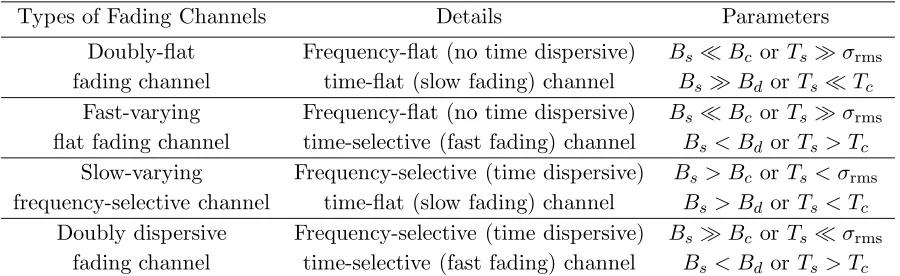
In general, there are four types of fading channels, as shown in Table 2.3.
Frequency Flat Fading If the RMS multipath delay spread of a wireless channel is much shorter than the symbol period, in other words, the channel coherence bandwidth
is wider than the signal bandwidth as
σrmsTs and Bc Bs, (2.11)
the channel is referred to as the exhibiting frequency flat fading. In this type of channel,
the gains can maintain approximately constant amplitudes and linear phase responses
in the frequency domain. The signal is transmitted over the flat response of a channel.
The previously arriving symbols do not affect the current arriving symbol. Thus, the
ISI is not significant.
Frequency Selective Fading If the RMS multipath delay spread of a wireless chan-nel is longer than the symbol period, and the chanchan-nel coherence bandwidth is smaller
than the signal bandwidth as
σrms> Ts and Bc < Bs, (2.12)
the channel is termed as the exhibiting frequency selective fading, typicallyTs≤10σrms. Since the symbol duration is shorter than the multipath delay spread of a channel,
multiple-delayed versions of the transmitted signals overlap together with the currently
arriving symbols, causing the ISI. The received signals undergo varying amplitudes in
Table 2.3: Summary of Fading Channels.
Types of Fading Channels Details Parameters
Doubly-flat fading channel
Frequency-flat (no time dispersive) time-flat (slow fading) channel
BsBc or Tsσrms BsBd or Ts Tc
Fast-varying flat fading channel
Frequency-flat (no time dispersive) time-selective (fast fading) channel
BsBc or Tsσrms Bs< Bd or Ts > Tc
Slow-varying
frequency-selective channel
Frequency-selective (time dispersive) time-flat (slow fading) channel
Bs> Bc or Ts< σrms Bs > Bd or Ts< Tc
Doubly dispersive fading channel
Frequency-selective (time dispersive) time-selective (fast fading) channel
BsBc or Tsσrms Bs< Bd or Ts > Tc
Slow Fading If the coherent time of a channel is much longer than the symbol duration, and the Doppler spread of a channel is smaller than the signal bandwidth as
Tc Ts and BdBs, (2.13)
the channel is referred to as exhibiting the slow fading. This type of Channel Impulse
Response (CIR) varies relatively slowly compared to the symbol duration. Thus, the
channel can remain uniform over the period of a number of symbols. In this case, the
effect of the Doppler spread is negligible at the receiver. In reality, most situations
exhibit the slow fading.
Fast Fading If the coherent time of a channel is shorter than the symbol duration, and the Doppler spread of a channel is larger than the signal bandwidth as
Tc< Ts and Bd> Bs, (2.14)
the channel is termed as the exhibiting fast fading. The channel variation changes
rapidly so that the signal might experience different channel conditions within one
symbol duration.
Rician and Rayleigh Fading and Channel Model
The rapid fading condition causes either a Rician or Rayleigh distribution. In an LOS
while in a Non Line-of-Sight (NLOS) environment, the Rayleigh distribution is an
ap-proximation for mobile fading channels. Wireless communication channels, in the either
LOS or NLOS path case, can be represented by Independent Identically Distributed
(i.i.d.) Gaussian complex random variables with a zero mean and a variance ofσ2 fading.
The Rician Probability Density Function (PDF) is given by [13] [15]
PRician(x) = x σ2
fading e−
x2 2σ2
fadinge−KI0
x√2K σfading
, (2.15)
wherexis the amplitude of the received signal, I0(·) is the modified Bessel function of
the first kind and zero order, andK = σ2A2
fading denotes the measurement of the ratio of
the power received in the LOS path to the total power received via other NLOS paths,
withAbeing the peak amplitude of dominant signal via the LOS path. AsK→ ∞, the
signal component via the LOS path becomes dominant. As K →0, the signal via the
LOS path becomes weaker, the Rician distribution reduces to the Rayleigh distribution,
with the PDFPRayleigh(x) given as
PRayleigh(x) = x σ2fadinge
−2σ2x2
fading. (2.16)
Assuming a total number of Lpaths between transmitter and receiver, the CIR of
a Rayleigh fading channelh(t) can be given by
h(t) =
L−1 X
i=0
αiejφiδ(t−σfading,i), (2.17)
whereαi is independent, and satisfies the Rayleigh distribution in Equation (2.16) for
thei-th path,φi is uniformly distributed between [0,2π], andσfading,iis the time delay
for thei-th path. AsL= 1, the channel becomes flat fading represented as
h(t) =α1ejφ1δ(t). (2.18)
Clarke’s channel model [13] [14] [15], confirmed by measurements in urban
envi-ronments, has been widely used in the literature. Thus, it is also employed in this
2.2
Wireless Communication Systems
2.2.1 OFDM Technology
To eliminate the ISI due to multipath, traditional time-domain equalization schemes
[16] [17] [18] in the literature require complex implementation, and thus are practically
impossible. Due to technological development, the digital implementation of the pair
of Fast Fourier Transform (FFT) and Inverse Fast Fourier Transform (IFFT) becomes
simple and practically possible. OFDM technology, proposed in 1960 [9], is attractive
for simplifying the equalization process at the receiver for frequency selective fading
channels [19]. So far, OFDM has been chosen for the wireless local area networks IEEE
802.11 standards [6], and has been adopted by LTE-Advanced [7] [8]. Also, it has been
selected as a strong candidate for the WiGig [20] [21] and the Fifth Generation (5G)
wireless communication [22] [23] in the future, respectively.
Principle of OFDM
Different from the single carrier modulation which has a relatively low data rate, the
multi-carrier modulation [19] is employed to support high data rates in OFDM
tech-nology. In OFDM, a frequency band is divided into a number of closely spaced
spec-trums. Thanks to the orthogonal property of subcarriers, the centre frequency of one
subcarrier can coincide with the spectral zeros of all other subcarriers, leading to no
interference between subcarriers. To guarantee the orthogonality between subcarriers,
a small spacing between subcarriers is used in OFDM systems, while a bigger spectral
width between parallel channels is used to avoid the interference in traditional
Fre-quency Division Multiplexing (FDM) systems [24] [25]. Therefore, OFDM systems can
achieve higher spectral efficiency than FDM systems.
In order to combat frequency selective fading, a high-rate transmit stream is divided
s c
B
B
Deep Fading
Bc
Bs
s c
B
B
Bc = Coherence Bandwidth
Bs= Symbol Bandwidth
Bc
Bs
Flat Fading Before OFDM
[image:35.612.153.532.95.448.2]After OFDM
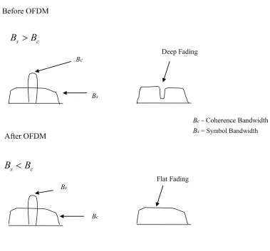
Figure 2.2: Coherent bandwidth and signal bandwidth before and after OFDM
subcarrier is prolonged, and the signal bandwidth becomes shorter in comparison to
the channel coherence bandwidth, as shown in Figure 2.2. Assuming that the channel
variation is slow, the symbol durationTs can satisfy
σrms< N Ts< Tc, (2.19)
where N is the number of subcarriers, σrms and Tc are the RMS delay spread of the
channel and the channel coherent time, respectively.
Therefore, the frequency selective fading channel can be divided into a number of
equaliza-tion with lower complexity than that employed in tradiequaliza-tional methods as in [16] [17]
[18].
Drawbacks of OFDM
Although OFDM can combat frequency selective fading, there are some drawbacks to
OFDM systems. In this subsection, the effects of CFO, Symbol Time Offset (STO),
Inphase/Quadrature (I/Q) imbalance and Peak-to-Average Power Ratio (PAPR) are
analyzed, respectively.
CFO In general, there are two types of distortion with respect to the CFO. Firstly, the signal is converted up to a passband by a carrier at the transmitter, and converted
down to the baseband by the same carrier at the receiver, via LOs. This type of CFO
is caused by the unavoidable difference of LOs between transmitter and receiver, and
can be divided into an integer part and a fractional part. The integer part of CFO
gives rise to a cyclic shift in the received signals, while the fractional part destroys
the orthogonality between OFDM subcarriers, and results in the ICI. Secondly, the
CFO can be caused by a Doppler frequency shift, which also destroys the orthogonality
between OFDM subcarriers. As a result, either type of CFO can incur a significant
degradation in BER performance.
fr and ft are defined as the carrier frequencies at the receiver and transmitter,
respectively. The normalized CFO φcan be written as
φ= fr−ft
4f , (2.20)
where4f denotes the subcarrier spacing.
Define s= [s(0), s(1), . . . , s(N −1)]T as the transmitted signal vector. Considering
the effect of CFO, the received signal vector y(φ) = [y(φ)(0), y(φ)(1), . . . , y(φ)(N −1)]T in the frequency domain can be written as
where F is an N ×N Discrete Fourier Transform (DFT) matrix, with entry (a, b) given by F(a, b) = √1
Ne −j2πab
N ,(a, b = 0, . . . , N −1), and FH is an Inverse Discrete
Fourier Transform (IDFT) matrix,Φ(φ)= diag{[0, ej2Nπφ, . . . , e
j2πφ(N−1)
N ]}is the diagonal
CFO matrix, with diag{x} denoting a diagonal matrix whose diagonal elements are entries of vector x, H= diag{[H(0), H(1), . . . , H(N −1)]} is the diagonal frequency-domain channel matrix, with H(n) denoting the channel frequency response on the
n-th subcarrier, andzf is the N ×1 noise vector.
The normalized CFO φcan be divided into an integer partφi and a fractional part
φf, respectively [12] [26], expressed as
φ=φi+φf, (2.22)
whereφi =bφic, withbxc denoting a largest integer less than or equal to scalar x.
Integer CFO If the fractional CFO is zero, i.e., φf = 0, the CFO is caused
by the integer part only. The cyclic shift matrix induced by the integer CFO is
written as C(φi) = FΦ(φi)FH, with the n-th row of C(φi) denoting [C(φi)](n,:) = [01×(N−n−φi),1,01×(n+φi−1)]. With the effect of the integer CFO, the received symbol y(φi)(n) on the n-th subcarrier is the φ
i-th cyclicly shifted version, written as
y(φi)(n) =H(n−φi)s(n−φi) +zf(n), (2.23)
where zf(n) is the noise on the n-th subcarrier. That means the symbol transmitted
on the (n−φi)-th subcarrier is received on then-th subcarrier. The cyclic shift in the
received signal could incur a significant degradation in BER performance. However,
the orthogonality between subcarriers remains, and thus the ICI does not occur.
Fractional CFO If the integer CFO is zero, i.e.,φi = 0, the CFO is caused by
the fractional part only. Note that the fractional CFO has a range of [−0.5, 0.5) [12].
ICI matrix C(φf) is circular, with each row equal to the previous one rotated by one element [27]. With the effect of the fractional CFO, the received signal vector y(φf)
can be written as
y(φf)=C(φf)Hs+zf. (2.24)
The frequency component on the n-th subcarrier is affected by the ICI from other
(N−1) subcarriers. In such a case, the orthogonality between subcarriers is destroyed
by the fractional CFO. In the following part, the fractional CFO estimation is the focus
in this thesis, assuming that the integer CFO is eliminated. This assumption is valid
in systems where the integer CFO is well compensated for, before the fractional CFO
is estimated using an algorithm whose performance is not affected by the presence of
the integer CFO [12].
In a fast moving environment, the Doppler shift is determined by carrier frequency
and velocity. This effect gives rise to time-varying channels in the time domain, and a
frequency drift between subcarriers in the frequency domain. Thus, the orthogonality
between subcarriers could not be maintained.
STO In OFDM systems, the timing synchronization is required to detect the starting point of each OFDM block. The imperfect location of the detected starting point gives
rise to the STO, and might have different effects, either ISI or phase rotation. The
estimated location could be a little early, much too early, or a little later than the real
starting point [12]. Assume that the length of the Cyclic Prefix (CP) extends over the
last few copies of each OFDM block, and is larger than the multipath delay spread.
There are three effects of the STO, as follows
• A little early[12]: if the detected point is a bit earlier than the real point but still in the current block, while being later than the end of the lagged arriving
symbols, the orthogonality between subcarriers can be maintained with no ISI
OFDM block.
• Much too early [12]: if the detected point is located prior to the end of the arrival of the lagged arriving symbols in the previous block, the Inter-Block
In-terference (IBI) occurs, resulting in the ISI.
• A little late[12]: if the detected point is later than the real timing instant, the next block brings the interference to the current block, also involving the ISI.
I/Q Imbalance Due to the drive of low cost and low power consumption, Direct Conversion Architecture (DCA) has become a trend for the front-end design,
particu-larly in OFDM based wireless communication systems [28]. However, I/Q imbalance is
induced by the DCA, including frequency independent and frequency dependent I/Q
imbalances, at the transmitter and the receiver [29] [30]. The frequency-dependent I/Q
imbalance is caused by mismatching components in I and Q branches, and is frequency
selective. The frequency-independent I/Q imbalance results from non-ideal LOs
be-tween transmitter and receiver, and remains constant over the whole signal frequency
band. In OFDM systems, the I/Q imbalance gives rise to a mirror subcarrier
interfer-ence, which can produce an error floor, degrading system performance severely.
PAPR The application of the IFFT at the transmitter enables the transmitted signals to have higher peak values, compared to the average signal level in the time domain.
Thus, there is a high PAPR in OFDM systems. The signals with high PAPR require
a power amplifier with a wide bandwidth linear range. It is even more critical for the
uplink, as the high PAPR problem reduces the battery life of mobile terminals. The
PAPR of the complex passband signal s(t) is defined as the ratio of the maximum
power to the average power ins(t), written as [31] [32]
P AP R{s(t)}= max|s(t)| 2
E{|s(t)|2}, (2.25)
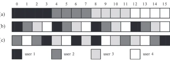
Figure 2.3: CAS in OFDMA systems: (a) subband CAS, (b) interleaved CAS and (c) generalized CAS
OFDMA
Recently, OFDMA, derived from OFDM, has attracted much research attention. It has
been adopted by the Interaction Channel for Digital Terrestrial Television (DVB-RCT)
[33], and the wireless local area networks IEEE 802.11 standards [6] [34].
Different from OFDM systems in which a single user occupies all subcarriers for
the signal transmission, OFDMA systems allow multiple users to transmit symbols
simultaneously using different orthogonal subcarriers. In OFDMA systems, a subset of
subcarriers is assigned to each user, and the number of subcarriers for an individual user
can be adaptively varied in each frame. Furthermore, OFDMA systems can provide a
relatively lower PAPR than OFDM systems.
OFDMA has dynamic resource allocation, as it allows users to select their own
subset of subcarriers according to channel conditions. Generally, there are three kinds
of Carrier Assignment Scheme (CAS) available for users in OFDMA systems: subband
CAS, interleaved CAS and generalized CAS, as shown in Figure 2.3 [35].
• Subband CAS: several adjacent subcarriers are composed into a subblock to be allocated for an individual user.
• Generalized CAS: individual subcarrier can be assigned to any user, allowing dynamic resource allocation, since no specific rigid relationship between users and
subcarriers exists.
Let N and K denote the total number of subcarriers and the number of users,
respectively. In OFDMA systems, one subcarrier can be assigned to one user only,
and could not be occupied by other users. Assume that all the subcarriers are used
for the transmission with no virtual or null subcarrier. Define Ωk(i) as the subset of
the number of subcarriers allocated to the k-th user (k = 0,1,· · · , K−1) in the i-th
OFDMA block. It can be written as
Ωk(i) ={Ωk(0, i), Ωk(1, i), · · · , Ωk(N −1, i)}, (2.26)
where Ωk(n, i) denotes the indicator of subcarrier allocation for the k-th user on the
n-th subcarrier in thei-th OFDMA block, given as
Ωk(n, i) =
(
1 if Ωk(n, i) occupied by thek-th user
0 if Ωk(n, i) not occupied by thek-th user
. (2.27)
The union of subsets of subcarriers forK users satisfies
Ω0(i) [
Ω1(i) · · · [
ΩK−1(i) = Y
N
={N}, (2.28)
The intersection of subsets of subcarriers forK users satisfies
Ω0(i) \
Ω1(i) · · · \
ΩK−1(i) = Ø, (2.29)
where Ø denotes an empty set. Let xk(n, i) denote the symbol on then-th subcarrier
in the i-th block, and transmitted by the k-th user. After subcarrier allocation, the
resulting symbolsk(n, i) in OFDMA systems is given by
sk(n, i) =xk(n, i)·Ωk(n, i). (2.30)
The orthogonality between subcarriers provides the intrinsic protection against the
to have a simple equalization scheme in the frequency domain. However, there are
several technical challenges in OFDMA systems, some of which are frequency and
timing synchronisation. Similar to OFDM, OFDMA is extremely sensitive to the CFO
and STO [12] [36] [37]. As discussed previously, The CFO destroys the orthogonality
between subcarriers and results in the ICI. The STO gives rise to either the ISI or
phase shift in the received signals. In particular, multiple users are allowed to transmit
simultaneously in OFDMA systems, posing more challenges for CFO and
multi-STO estimation. In Chapter 6, a joint algorithm for ICI mitigation and equalization is
proposed in the OFDMA uplink.
2.2.2 MIMO OFDM Systems
To improve system capacity, multiple transmit and receive antennas are employed to
establish multiple spatial branches, referred to as MIMO systems [38]. Compared to
traditional SISO systems, MIMO systems can increase bandwidth efficiency, as
multi-ple transmit and receive antennas operate on the same frequency band for the signal
transmission. In order to combat frequency selective fading, OFDM is well suited for
use in MIMO systems. Also, equalization can be simplified in the frequency domain for
OFDM based systems. Therefore, MIMO OFDM systems have been adopted by the
wireless local area networks IEEE 802.11 standards and LTE Advanced, respectively
[6] [7] [8]. However, as the prorogation path between each transmit antenna and each
receive antenna is independent, MIMO OFDM systems give rise to an additional spatial
interference, known as the Co-Antenna Interference (CAI) or Co-Channel Interference
(CCI) [14], which needs to be eliminated.
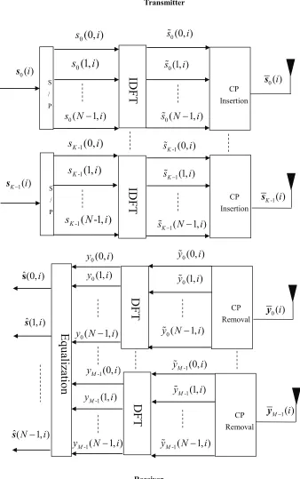
An MIMO OFDM system is considered, withKtransmit andM receive antennas in
the frequency selective fading environment, as illustrated in Figure 2.4. The incoming
serial data at the transmitter is divided into parallels. The IDFT/DFT pair allows the
S / P
ID
F
T
CP Insertion Transmitter Receiver0
(0, )
s
i
0
(1, )
s
i
0( 1, )
s N i
0(0, )
s i
0(1, )
s i
0( 1, )
s N i
0( )i s
CP
Removal 0
( )i
y 0(0, )
y i
D
F
T
0(1, )
y i
0( 1, )
y N i
0(0, )
y i
0(1, )
y i
0( 1, )
y N i
ˆ(N 1, )i
s
0( )i s S / P
ID
F
T
InsertionCP-1
(0, )
K
s
i
-1
(1, )
K
s
i
-1
( -1, )
K
s
N
i
-1(0, )
K
s i
1(1, )
K
s i
1( 1, )
K
s N i
-1( )
K i
s
CP Removal
-1(1, )
M
y i
-1(0, )
M
y i
-1( 1, )
M
y N i
D
F
T
-1( 1, )
M
y N i
-1(1, )
M
y i
-1(0, )
M
y i
ˆ(1, )i
s
ˆ(0, )i s
1( )
K i
s
1( )
[image:43.612.151.489.100.639.2]M i y
E
q
u
al
iz
at
io
n
sk(n, i) denote the symbol on then-th subcarrier (n= 0,1, . . . , N−1) in thei-th block
(i= 0,1, . . . , Ns−1) transmitted by the k-th transmit antenna (k = 0,1, . . . , K −1).
Define sk(i) = [sk(0, i), sk(1, i). . . , sk(N−1, i)]T as the signal vector in thei-th block
for the k-th transmit antenna. Details of the entire process of the data transfer from
transmitter to receiver via channels are described in the following steps.
At the transmitter, the signal in the i-th OFDM block is first transformed to the
time domain as ˜sk(i) by the IDFT as
˜
sk(i) =FHsk(i), (2.31)
whereFis anN×N DFT matrix, with entry (a, b) given byF(a, b) = √1
Ne −j2πab
N ,(a, b=
0, . . . , N −1), andFH is an IDFT matrix, withFH =F−1 sinceFis a unitary matrix [27]. Note that the computationally efficient IFFT/FFT pair may also be employed.
Assuming a total number ofL channel paths, a CP of length LCP, at least LCP ≥
L−1, is attached to each OFDM block ˜sk(i). The guard symbols consist of a copy of
the lastLCPentries of each OFDM block. The insertion of a CP has two purposes: IBI
avoidance and circular convolution between time-domain signal and CIR. With the CP
insertion, the transmitted signal vector ¯sk(i) can be given as
¯sk(i) =TCP˜sk(i), (2.32)
where TCP = [ITCP,ITN]T is the (LCP+N)×N matrix, with IN denoting an N ×N
identity matrix andICP denoting the last LCP rows ofIN.
The signal is then transmitted through the frequency selective fading channel, which
is assumed to be constant for the duration of a frame consisting of a total number of
Ns OFDM blocks. This is a convolution process as shown in Figure 2.5. The received
signal vector ¯ym(i) = [¯ym(0, i),y¯m(1, i). . . ,y¯m(N−1, i)]T at them-th receive antenna
(m= 0,1, . . . , M −1) in the time domain can be written as
¯
ym(i) =
K−1 X
k=0 ¯
D
D
…
D
Channel Output
Convolution
Process
,(1)
m kh
h
m k,(
L
1)
,
( )
m k
y
n
[image:45.612.136.529.375.475.2]Channel Input
Figure 2.5: Convolution process of signal and channel for MIMO OFDM systems
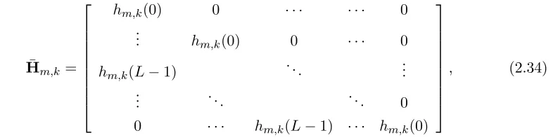
where ˜Hm,k is the (LCP+N)×(LCP+N) convolutional channel matrix between the m-th receive antenna and thek-th transmit antenna, given as
¯
Hm,k =
hm,k(0) 0 · · · 0
..
. hm,k(0) 0 · · · 0
hm,k(L−1) . .. ...
..
. . .. . .. 0
0 · · · hm,k(L−1) · · · hm,k(0)
, (2.34)
where hm,k(l) is the l-th (l = 0,1, . . . , L−1) channel path between the m-th receive
antenna and the k-th transmit antenna, and ¯zm(i) is the Additive White Gaussian
Noise (AWGN) vector whose entries are i.i.d. complex Gaussian random variables with
a zero mean and a variance ofN0 [38].
After the CP is removed, the received signal vector ˜ym(i) at the m-th receive an-tenna can be written as
˜
ym(i) =RCPy¯m(i), (2.35)
whereRCP= [0N×LCP,IN] is theN ×(LCP+N) matrix used to remove the CP, with 0N×LCP denoting the N×LCP matrix filled with zeros.
DFT matrix to ˜ym(i) as
ym(i) =Fy˜m(i). (2.36)
The full circular convolution process between channel and signal can be achieved using
the CP. The time-domain circular convolution can be transformed to a linear
multi-plication in the frequency domain by applying the IDFT /DFT pair, leading to simple
equalization for the frequency selective fading environment [39]. The circulant matrix
is a Toeplitz matrix where each row is equal to the previous one rotated by one element
[27]. By using the IDFT /DFT pair, the circulant matrix can be diagonalized [27]. The
resulting transceiver signal model in the frequency domain can be written as
ym(i) =
K−1 X
k=0
Hm,ksk(i) +zm(i), (2.37)
whereHm,k =FH˜m,kFH is the diagonal frequency-domain channel matrix, with ˜Hm,k = RCPH¯m,kTCP denoting the equivalent circulant channel matrix. The entry (n, n) in
Hm,k is written as Hm,k(n, n) =PLl=0−1hm,k(l)e− j2πnl
N , and zm(i) = FRCP¯zm(i) is the
frequency-domain noise vector. Note that the distribution statistics of the channel can
be preserved by the DFT [38], if the CIR hm,k(l) is assumed to have the Rayleigh
distributed magnitude and uniformly distributed phase. Also, the distribution of the
white Gaussian noise samples can be preserved by the DFT.
Finally, the Frequency Domain Equalization (FDE) can be performed on each
sub-carrier in MIMO OFDM systems, since the frequency selective fading channel is divided
into a number of flat fading channels. Defines(n, i) = [s0(n, i), s0(n, i), . . . , sK−1(n, i)]T as the signal vector fromK transmit antennas on then-th subcarrier in thei-th block.
The received signal vector y(n, i) = [y0(n, i), y1(n, i), . . . , yM−1(n, i)]T in the frequency domain on then-th subcarrier can be written as
y(n, i) =H(n)s(n, i) +z(n), (2.38)
m-th receive antenna and thek-th transmit antenna, andz(n) is the noise vector. The source data estimate ˆs(n, i) can be performed by either Zero Forcing (ZF) or Minimum Mean Square Error (MMSE) based equalization on the received signal on the n-th
subcarrier as
ˆs(n, i) =G(n, i)y(n, i), (2.39)
whereG(n, i) is the weighting matrix that can have either ZF or MMSE equalization criterion. The details of these equalization schemes are provided in Chapter 3.
2.2.3 CoMP Transmission
The inter-cell interference is a major bottleneck for achieving very high data rates
in wireless communication systems [14]. Previously, adjacent cells were operated on
different frequencies to effectively reduce the inter-cell interference [40]. Recent research
trends hint that millimeter (mm) wave communication will be the key component in 5G
cellular systems. The short coverage of mm wave bands results in small cells. As the
demand for high mobile data rates grows, higher spectral efficiency of cellular networks
is needed, with full frequency reuse [41] [42]. One of best ways to manage interference
is to allow each BS to connect to each other through a backhaul link. The BSs could
exchange messages and jointly process received multiple users’ signals on the same
frequency band. This structure, called CoMP, has been adopted by LTE-Advanced [3].
CoMP transmission explores the interference between cells, which is different from other
existing methods by treating them as noise [43] [44]. These features of CoMP systems
are important for users at the cell-edge to have effective communication through the
BSs. Also, CoMP is a cost-effective structure, as it requires little change to the current
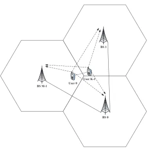
system. The general CoMP system diagram is illustrated in Figure 2.6.
CoMP transmission has some significant challenges, which are summarized as
fol-lows.
mul-BS 0 User 0
BS 1
BS M-1
[image:48.612.204.509.90.395.2]User K-1
Figure 2.6: Wireless CoMP system model with K users and M BSs
tiple CFOs in the OFDM based CoMP transmission. The multi-CFO estimation
becomes much difficult so that conventional frequency synchronization schemes
for a single CFO are not suitable in the scenario. Compared to OFDMA systems,
multi-CFO estimation in the CoMP transmission is much more challenging. There
are two reasons. Firstly, the CoMP system allows users to transmit signals
simul-taneously by using all shared subcarriers, while multiple users could not share
the same subcarriers in OFDMA systems. In the presence of multiple CFOs, one
user’s signal power is leaked into other users in OFDMA systems. The effect
disappears with correct CFO compensation. By using this property, a number of
multi-CFO estimation approaches were proposed for OFDMA systems [36] [45].
However, in the CoMP transmission, different users’ signals interfere with each
no CFO. These multi-CFO estimation approaches used in OFDMA systems will
significantly degrade the performance in the CoMP transmission, and therefore,
are not suitable. Secondly, as frequency synchronization of all BSs and users is
required, the number of CFOs linearly increases with the increasing number of
BSs and users in the CoMP transmission. While in OFDMA systems, the number
of CFOs only increases with the number of users. Thus, the number of CFOs in
CoMP systems is larger than that in OFDMA systems.
• Multi-cell channel estimation and equalization: On the one hand, the central
station in the CoMP transmission requires additional time to collect all received
signals from multiple BSs for joint processing. This delay might cause a
seri-ous situation in time-limited communications. Thus, low-complexity multi-cell
channel estimation and equalization are important and challenging in the CoMP
transmission [46]. On the other hand, bandwidth resource is very scarce in
wire-less communication systems. Traditionally, training signals are commonly used
for channel estimation. However, transmitting training signals reduces spectral
ef-ficiency. Therefore, there is a trade-off between complexity and spectral efficiency,
when designing channel estimation and equalization schemes for the CoMP
trans-mission.
In Chapter 5, a low-complexity multi-CFO estimation method and an ICA based
equalization scheme are proposed for CoMP systems to well deal with the challenges
above.
2.2.4 CA Technology
Carrier Aggregation (CA), as one of key features in LTE-Advanced [3] [4], allows
sev-eral smaller component carriers (spectrum chunk) to be aggregated. Thus, high data
rates can be achieved in the CA transmission, by deploying extended bandwidth for
Figure 2.7: Intraband contiguous CA [5]
[image:50.612.166.459.81.420.2]Figure 2.8: Intraband non-contiguous CA [5]
Figure 2.9: Interband non-contiguous CA [5]
follows.
• High data rates: Up to five component carriers can be allowed for the
aggrega-tion in the both uplink and downlink. As the bandwidth is up to 20 MHz for
each component carrier, a maximum of 100 MHz is achieved in the supported
bandwidth for five component carriers in total. The peak target data rates are in
excess of 1 Gbps in the downlink and 500 Mbps in the uplink, respectively.
• Configuration flexibility: It is possible to have asymmetric configurations for
the CA at user and BS. Also, the number of component carriers could be used
differently in the downlink and uplink.
• Frequency flexibility: As the locations of users are different, they can select
com-ponent carriers based on several conditions, such as CSI. This can provide great
Figure 2.10: Inter-band non-contiguous CA block diagram at the transmitter
control and component carrier allocation.
• Interference management: the CA can be used as a promising cell
inter-ference coordinator, and is dependent on many factors: the relative locations of
BSs, traffic situation, the mutual interference coupling and so on. These factors
are configured to optimize system performance.
In terms of frequency location, there are three different aggregation scenarios, as
shown in Figures 2.7-2.9 [5]. These aggregation scenarios are described as below.
• Intra-band aggregation with contiguous carriers: A number of continuous
com-ponent carriers are aggregated within the same bandwidth.
• Intra-band aggregation with non-contiguous carriers: A number of separated
com-ponent carriers, belonging to the same bandwidth, are aggregated.
• Inter-band aggregation with non-contiguous carriers: A number of non-adjacent
![Table 2.1: Path Loss Exponent Values in Different Environments [13]](https://thumb-us.123doks.com/thumbv2/123dok_us/8071644.227024/27.612.187.447.103.218/table-path-loss-exponent-values-in-dierent-environments.webp)
![Figure 2.1: Indoor power delay profile [13]](https://thumb-us.123doks.com/thumbv2/123dok_us/8071644.227024/29.612.158.481.428.523/figure-indoor-power-delay-prole.webp)
![Figure 2.9: Interband non-contiguous CA [5]](https://thumb-us.123doks.com/thumbv2/123dok_us/8071644.227024/50.612.166.459.81.420/figure-interband-non-contiguous-ca.webp)

