Article
Hybrid Motor System for High Precision Position
Control of a Heavy Load Plant
Gridsada Phanomchoeng
1,2,*and Ratchatin Chancharoen
11 Department of Mechanical Engineering, Faculty of Engineering, Chulalongkorn University, Bangkok,
10330, Thailand
2 Applied Medical Virology Research Unit, Chulalongkorn University, Bangkok 10300, Thailand
*E-mail: gridsada.p@chula.ac.th (Corresponding author)
Abstract. The lift up or press process with high precision position control is an important
application in various industries. An example of this lift up and press is the process of a rapid prototype machine, powder based and metal-based 3D printer. It is difficult to design the mechanism and controller for base table accuracy, because it needs to control the base position of the system with the weight varying over a large range. Also, the friction in the system would vary accordingly. This leads to a low performance of the system in some range loads. Therefore, the new design system utilizes a DC motor and ball screw and a pneumatic actuator to create a hybrid motor to use for the lift up and press system. This pneumatic actuator is designed to support a heavy load and the DC motor and ball screw are designed to control the position. Thus, the developed hybrid motor can be used to improve the performance of the system. The simulation and experimental results show that the developed system improved the rise time, setting time and steady state error. The time response of the system with a heavy load looked similar to the time response of the system with a light load. Moreover, the developed hybrid motor technique can be used for other applications such as to control the 3D powder painter tank base position and the silicon injection system of the 3D print head, which is a challenge due to the high friction in the tube.
Keywords: Ball-screw, DC motor, pneumatic actuator, hybrid actuator, friction, PID
control.
ENGINEERING JOURNAL Volume 23 Issue 6
1.
Introduction
Currently, high precision positioning systems are widely used in many industry manufacturing processes [1] such as the assembly and inspection of microelectronic components of hard disk drives or in the automotive industries [2]. High precision performance demands have quickly increased due to the needs of improving both quality and speed [3-4]. Many types of actuators such as DC/AC motors or stepping motors with ball-screw/lead-screws, piezoelectric actuators as well as pneumatic or hydraulic actuators are used to develop high precision positioning systems [1-19]. Also, many sophisticated control techniques such as adaptive control [4-5,17], friction compensation [6], and slide mode control [7-8] have been developed to improve systems performance and to support manufacturing processes.
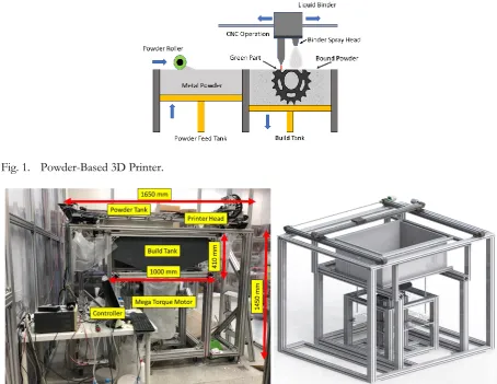
The lift up or press process with high precision position control is a special and important application in industries [20]. The demand for this type of application is increasing, for example as a machine tool for lifting and injection. Another significant challenge is the lift up and down process of a rapid prototype machine, powder based and metal-based 3D printer [21-22]. The process involves a buildup of many thin cross sections of the 3D model as shown in Fig. 1. Normally, a 3D printer has 2 tanks, one tank is the powder feed tank and the other is the build tank. The build tank is important, since the tank base position needs to be precisely controlled to obtain a high quality surface finish of the built part. Moreover, when the build tank is large, the weight of the powder inside the tank may be more than 1000 kilograms. An example of a powder-based 3D printer with 1000 kilograms capacity is shown in Fig. 2. Thus, it is difficult to design the mechanism and controller to control the tank base position accurately, because it needs to control the base position of the system with the weight varying from 0 to 1000 kilograms. Also, the friction in the system would vary in a large range.
Fig. 1. Powder-Based 3D Printer.
[image:2.595.67.522.367.718.2]The increasing demand on the performance and cost of the lift up and press system has driven researchers to develop a mechanism and control technique to improve the performance of the system [1-19].
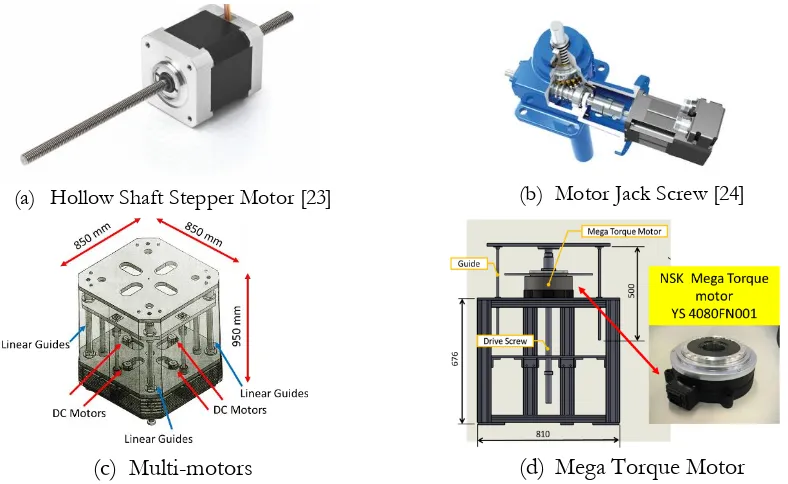
Since the load of the system is heavy and its position needs to be precisely controlled, most researchers focus on developing the mechanism with DC motors, gears and ball screws, because gears can efficiently increase the torque of DC/AC/stepping motors and ball screws can efficiently convert rotary motion into linear motion with high accuracy [1, 3-4, 6, 9, 11]. A lot of mechanisms have been designed for these purposes, such as the hollow shaft stepper motor as shown in Fig. 3(a) [23], the motor jack screw as shown in Fig. 3(b) [24], the parallel mechanism of motors and ball screws as shown in Fig. 3(c) [25], and the hollow shaft mega torque motor with ball screws as shown in Fig. 3(d).
(a) Hollow Shaft Stepper Motor [23] (b) Motor Jack Screw [24]
(c)
Multi-motors
(d)
Mega Torque Motor
Fig. 3. Examples of design mechanisms for the lift up and press system.
The hollow shaft stepper motor is the simplest mechanism for a lift up and down system, since it has only a stepper motor and a lead screw as its major components. By controlling the stepper motor, the design position of the system could be achieved. The Z Corp 3D Powder Printer is an example which uses this mechanism to control the base tank [25]. However, this mechanism cannot be used for a heavy load application due to the limited torque of the stepper motor.
The motor jack screw uses a DC/AC motor to drive the system. Since it has a gearbox, the force can be increased, and a small DC/AC motor could be sufficient. This mechanism can be used to lift up and down a heavy load such as a vehicle. However, it is not easy to precisely control the position of the system because of gear backlash, flexibility and hysteresis [11]. Also, this problem cannot be easily solved by designing an advanced control technique.
To avoid backlash,flexibility and hysteresis of gears, the parallel mechanism of motors and ball screws uses more than one set of motors and ball screws to drive the system. Each motor directly connects to a ball screw without any gears to minimize the mechanisms for driving. If multi mechanisms for driving are used, the accuracy of the system will diminish, due to backlash, flexibility and hysteresis of the mechanisms. Figure 3(c) shows an example of 4 sets of motors and ball screws to lift a 1000 kilogram load application. In this case, the force distribution of the system is better than the force of a system with one actuator. Also, since the position needs to be controlled and each motor has a high-power torque, a special controller has to be designed for driving all motors [9]. If one of motors does not work properly, the base tank may be skewed or damaged. Thus, the cost of this mechanism is high due to the number of motors and ball screws and a special controller.
[image:3.595.105.499.201.443.2]very large, and the distribution force to lift up and press the load looks like a point load. Also, during the operation, the motor consumes a lot of energy, since it is difficult to design a brake for this system.
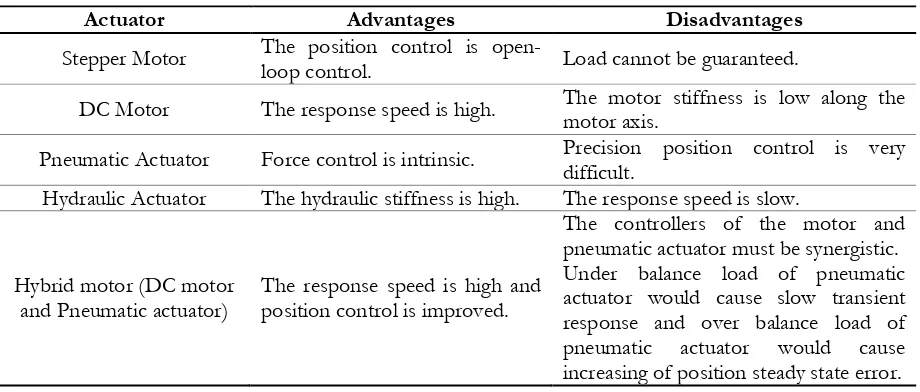
The summary of advantages and disadvantages of each type of actuators is also shown in Table 1. If the transient response, accuracy, and stability of the system are concerned, none of single actuator can give all the concerned performance indices. Also, using two or more actuators to combine their effects, they may interfere each other.
Table 1. Comparison of advantages and disadvantages each type of actuators.
Actuator Advantages Disadvantages
Stepper Motor The position control is open-loop control. Load cannot be guaranteed.
DC Motor The response speed is high. The motor stiffness is low along the motor axis.
Pneumatic Actuator Force control is intrinsic. Precision position control is very difficult. Hydraulic Actuator The hydraulic stiffness is high. The response speed is slow.
Hybrid motor (DC motor
and Pneumatic actuator) The response speed is high and position control is improved.
The controllers of the motor and pneumatic actuator must be synergistic. Under balance load of pneumatic actuator would cause slow transient response and over balance load of pneumatic actuator would cause increasing of position steady state error.
Not only the mechanism needed for the lift up and press system is vital, but the controller is also an important part of the system. A number of control design techniques have been developed [1, 3-11,17]. Most researchers tried to verify the model’s uncertainties and nonlinear friction and then developed a controller algorithm to compensate for them. For example, refs [1, 3, 7-8] verified the static and dynamic friction regimes and then applied sliding model controllers to a ball-screw-driven stage to improve the position control of the system. Ref. [4] confirmed the micro and macro dynamics of ball screws and applied a model reference adaptive control to control the system for small- and large-scale dynamics. Ref. [5] used an extended state observer to find the model’s uncertainties and applied a robust control to control the system. Ref. [6] estimated the friction parameters to control the system with a proportional-integral-derivative (PID) control and ref. [9] developed a control for the dual mechanically coupled parallel ball screws to synchronize the motion of the ball screws.
Even though many researches have proposed different techniques to improve the performance of the lift up and press system, the proposed techniques are still not suitable to apply in this case. For example, most of the control techniques focus on the verification of the model’s uncertainties and nonlinear friction and then develop an algorithm to estimate the friction parameters and compensate for them, but their techniques do not include a large load variation of the system. This leads to a low performance of the system over the whole range of load. Moreover, the developed control techniques may be suitable only for the system model which is close to the nominal model. Thus, this paper proposes a new mechanism design. The new design utilizes a DC motor and ball screw and a pneumatic actuator to create a hybrid motor system to apply to the lift up and press system. The pneumatic actuator is designed to support the heavy load and the DC motor and ball screw are designed to control the position. With both actuators, the system has the capability to support the heavy load and control the position of the system. Then, this control technique is further developed to improve the performance of an application, such as a powder-based 3D printer.
[image:4.595.69.529.188.384.2]2.
Lift Up and Press System
2.1. DC Motor and Ball Screw
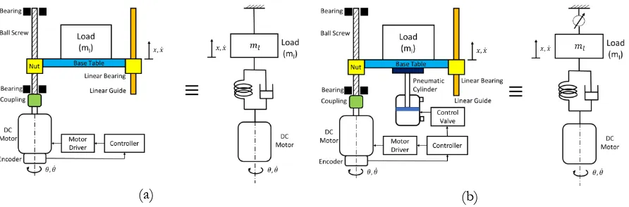
As shown in Fig. 4(a) the major components of the lift up and press system are composed of a DC motor with encoder, ball screw, linear guide and liner bearing, and a base table. The DC motor is used to drive the ball screw and the encoder is used to measure the angle of the motor shaft. The base table is attached to the nut of the ball screw and linear bearing. Thus, the displacement of the base table is controlled by the rotation of the ball screw.
Fig. 4. The vertical axis of the mechanical components of the system and a model of the system.
The system can also be presented as the model shown in Fig. 4(b). Since the stiffness of the ball screw and the connection between the nut and base table are finite, the model is simplified as a two-mass system. Thus, the dynamic motion of the system can be derived accordingly:
𝐽𝑚𝜃̈ + 𝑏𝑚𝜃̇ + 𝑘𝜃 = 𝑇 + 𝑘2𝜋
𝑃 𝑥 − 𝜓
𝑚𝑙𝑥̈ + 𝑏𝑙𝑥̇ + 𝑘𝑥 = 𝑘 𝑃 2𝜋𝜃
(1)
where the variables 𝜃, 𝑥 are the motor angle and the table displacement respectively, 𝐽𝑚 is the total rotational inertia of the motor and screw, 𝑏𝑚 is the damping coefficient of the motor, 𝑘 is the equivalent stiffness of the ball screw, 𝑇 is the motor torque, 𝑃 is the pitch of the ball screw, 𝜓 is the nonlinear friction of the system, 𝑚𝑙 is the mass of the system including the load, and 𝑏𝑙 is the damping coefficient of the table.
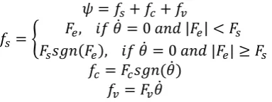
Based on Eq. (1), the accuracy of the system depends on the nonlinear friction 𝜓, which happens at the contact between nut and ball screw. For nonlinear friction, many friction models have been developed, such as the bristles deflect model [3, 6, 26], the static/dynamic friction model [3], the magic formula tire model [27, 28], or classical models [27]. In this case, only three terms were fixated. The nonlinear friction 𝜓, is shown in Eq. (2).
𝜓 = 𝑓𝑠+ 𝑓𝑐+ 𝑓𝑣
𝑓𝑠= { 𝐹𝑒, 𝑖𝑓 𝜃̇ = 0 𝑎𝑛𝑑 |𝐹𝑒| < 𝐹𝑠 𝐹𝑠𝑠𝑔𝑛(𝐹𝑒), 𝑖𝑓 𝜃̇ = 0 𝑎𝑛𝑑 |𝐹𝑒| ≥ 𝐹𝑠
𝑓𝑐 = 𝐹𝑐𝑠𝑔𝑛(𝜃̇) 𝑓𝑣= 𝐹𝑣𝜃̇
(2)
[image:5.595.190.408.205.340.2] [image:5.595.184.376.621.693.2]Fig. 5. Example of friction models: Fig. (a)shows Coulomb friction; Fig. (b) is Coulomb plus viscous friction; and Fig. (c) is stiction plus Coulomb and viscous friction.
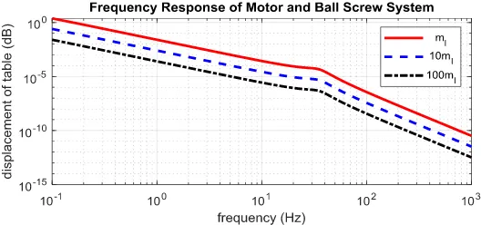
The load of the lift up and press system varies in a large range. Figure 6 shows the frequency response of the system with different loads. The frequency response shows that once the load is increased, the transient response of the system is increased, because the gain magnitude is decreased, and the motor torque is limited. Moreover, if the controller is not adjusted, the accuracy of the system position will be decreased.
Fig. 6. Frequency Response of Motor and Ball Screw System without Friction.
Since the load of the lift up and press system varies in a large range and the friction is nonlinear, it is not easy to design a controller for this system. Thus, the next section will present the new mechanism designed for this application.
3.
Hybrid Motor
Due to the problems with the DC motor and ball screw system, it is difficult to design a system with only the DC motor and ball screw. Using multi sets of DC motors and ball screws can solve the torque limitation of the system, but it complicates the mechanisms and controller. The system needs to be designed to prevent the mechanism conflict and the controller needs to synchronize the motors. To avoid these problems, a hybrid motor system was designed. A pneumatic cylinder was selected to be installed in the original system. The pneumatic actuator is designed to support the heavy load and the DC motor and ball screw are designed to control the position. Then, the pneumatic cylinder is used to supply the extra force to the system. The force from the pneumatic cylinder is simply controlled by controlling the pressure supplied to the cylinder without controlling the pneumatic cylinder position. Thus, there is not mechanism conflict in this system. Also, the pneumatic force can be used to balance the load, so a high torque from the DC motors is not required. Moreover, it can reduce the friction coefficient due to the load of the system. Therefore, it is not too difficult to design a controller to compensate for the friction in this case.
[image:6.595.113.479.89.228.2] [image:6.595.159.423.340.464.2](a) (b)
Fig. 7. Compression of dc motor and ball screw system and hybrid motor system: (a) The vertical axis of the mechanical components of the system and a model of the system; (b) Hybrid motor with pneumatic cylinder and a model of the system
Based on Eq. (1), the dynamic motion of the original system, the dynamic motion of the hybrid system is shown in Eq. (3).
𝐽𝑚𝜃̈ + 𝑏𝑚𝜃̇ + 𝑘𝜃 = 𝑇 + 𝑘2𝜋
𝑃 𝑥 − 𝜓
𝑚𝑙𝑥̈ + 𝑏𝑙𝑥̇ + 𝑘𝑥 = 𝑘 𝑃
2𝜋𝜃 + 𝐹𝑝
(3)
where 𝐹𝑝 is the pneumatic force.
3.1. Simulation Results
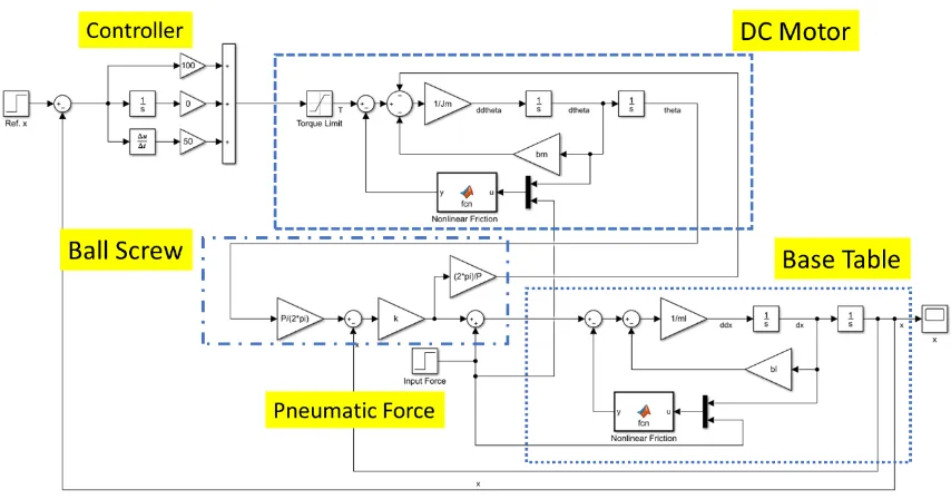
In order to check the performance of the hybrid motor system, the simulation was implemented on the Matlab Simulink, as shown in Fig. 8, based on Eq. (3). The Simulink model consists of a DC motor model with nonlinear friction and a torque limit, ball screw model, base table model with nonlinear friction, pneumatic force, and PD controller. The PD controller was used instead of a PID controller, because only the effect of the hybrid motor needed to be shown. If a PID controller was used in this case, the stead error would convert to zero. Next, the target displacement of the base table was set to be one. Three simulation models with the same PD controller were simulated. The first simulation projected that the system had a light load and would not apply a pneumatic force. The second simulation projected that the system had a heavy load and would not apply a pneumatic force. Lastly, the system with a heavy load and pneumatic force was simulated. All the results are shown in Fig. 9.
[image:7.595.78.524.89.236.2]Fig. 8. Control diagram of the hybrid motor system.
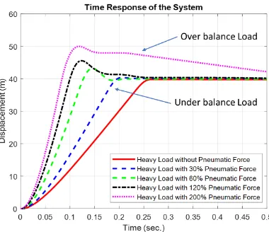
Fig. 9. Time response of the system.
[image:8.595.83.510.77.301.2] [image:8.595.195.389.342.496.2]Fig. 10. The time response of the system in the case of a variety of pneumatic force.
4.
Experimental Setup and Results
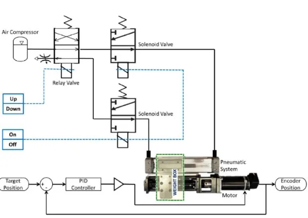
To confirm the performance of the hybrid motor, the developed system is shown in Fig. 11. It consists of a THK linear slide, THK TSKR S/N AR09B00001, with a ∅6x5 mm ball screw and the pneumatic cylinder, Koganei ORV 16x75-1003W. The base table is mounted on the nut of the ball screw and connected to the plate of the pneumatic cylinder. Thus, the working distance of the system is 60 millimeters. Then, the linear slide is derived by a 12-Volt DC motor, Maxon Motor 222524, with an optical encoder, HEDS-5540 C11. The resolution of the encoders is 500 pulses per revolution. Moreover, the pneumatic cylinder is controlled by pneumatic control values, SMC SY3120-5LZ-C4, and two solenoid valves, SMC VT307-5GS-01-F.
To control the position of the motor and the pneumatic control values, a control box was designed by a microcontroller, 86Duino One and a motor driver, VNH5019 motor driver carrier. This controller box also provides a serial port and a TCP/UDP port for communicating with a computer. Then, a low-level control is developed on the controller box and a high-level control on the computer. The wiring diagram of the system is presented in Fig. 12.
The architecture of the system control is shown in Fig. 13. In this case, the standard PID controller was selected to evaluate the system. Only the signal from the motor encoder sensors were used as feedback to the controller. To obtain a high-speed control, the control, PID, for the position control of the motor was designed in the control box (86Duino One). The PID controller is shown in Eq. (4) [29]. Then, with this control box, the sample rate can be achieved at 1000 Hz. Moreover, the control box can also communicate with the computer through its UDP port.
𝑒(𝑛) = 𝑦(𝑛) − 𝑦(𝑛 − 1)
𝑢(𝑛) = 𝐾𝑝𝑒(𝑛) + 𝐾𝑖∑ 𝑒(𝑘) + 𝐾𝑑(𝑦(𝑛) − 𝑦(𝑛 − 1) 𝑛
𝑘=0
) (4)
where 𝑛 is the discrete step at time 𝑡, 𝐾𝑝, 𝐾𝑖, 𝐾𝑑 are the constant gains, 𝑢 is the input, 𝑒 is the measured error, and 𝑦 is the measured output.
[image:9.595.200.390.82.246.2]Fig. 11.
The components of the system.Fig. 12. Wiring diagram of the system.
[image:10.595.143.452.514.733.2]4.1. Experimental Results
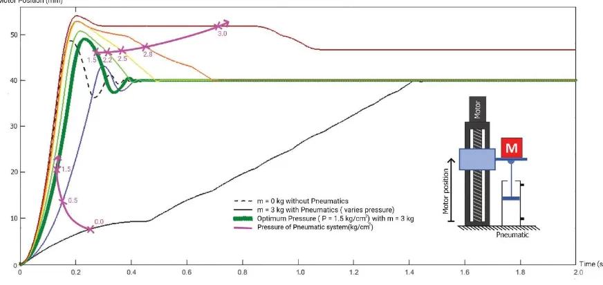
Three experiments with the same PID controller were run for the test; the target displacement of the base table for all experiments was set for 40 millimeters. In the first experiment the system had a 1-kilogram load (light load) and did not turn on the pneumatic cylinder. In the second experiment the system had a 3-kilograms load (heavy load) and does not turn on the pneumatic cylinder. Lastly, the system with 3-3-kilograms load (heavy load) and the pneumatic force was turned on at different pressure. All results are shown in Fig. 14. The result of the first experiment is presented by the dash black line on Fig. 14. The rise time was approximately 0.1 second, the peak 48 millimeters, the overshoot approximately 20 percent, and the setting time approximately 0.4 second. The steady state error converts to zero because of the PID controller. The solid black line shows the second experiment result. In this case, the DC motor power could not drive the base table to the target position easily, due to the load and friction. The rise time in this case was 1.3 second and the setting time 1.4 second. However, the steady state error could be converted to zero because of the PID controller.
Lastly, the solid lines with the purple x-marker and numbers are the responses of the third experiment at different pressures. The number represents the pressure of the pneumatic cylinder. When the pressure was increased, the rise time of the responses was reduced. For example, when the pressure was 0.5 kg/cm2, the rise time was about 0.25 second, and the setting time about 0.4 second. When the pressure was more than 1.5 kg/cm2, the rise time was less than 0.2 second. Also, these time responses were similar to the case where the system had a 1-kilogram load (light load) and the pneumatic cylinder was not turned on. However, when the pressure rose above 2.5 kg/cm2, it seemed that the pressure was too high and the friction of the system increased. However, the DC motor power cannot easily drive the base table to the target position. (Note: the steady state error of all setups converted to zero.)
In summary, the simulation results in Section 3 and the experiment results in Section 4 were congruous. A hybrid motor with the appropriate pressure of a pneumatic cylinder can be used to improve the performance of the lift up and press system, because the pneumatic cylinder can supply additional force to the DC motor to lift up or press the load and reduce the friction of the system. Moreover, the optimum pressure for this experiment was 1.5 kg/cm2 which is represented by the solid green line.
Fig. 14. Comparison of three experiment setup.
5.
Conclusions
[image:11.595.79.515.446.652.2]force and reduce the friction of the system. The time response of the system with a heavy load was similar to the time response of the system with a light load. Moreover, the developed hybrid motor technique can be used to control applications such as the 3D powder painter tank base position, the silicon injection system, as well as the 3D print head, which is a challenging system due to the high friction in its tube.
Acknowledgments
This work was a part of the Intelligent 3D Printing for Product Development Project which was supported by the 2nd Century Development Fund, Chulalongkorn University.
Item Sponsored by Ratchadaphiseksomphot Endowment Fund Chulalongkorn University: CU-GR_60_42_21_02.
References
[1] Y. F. Li and J. Wikander, “Discrete-time sliding mode control of a DC motor and ball-screw driven positioning table,” in Proc. IFAC 15th Triennial World Congress, Barcelona Spain, 2002, pp. 2436-2441. [2] K. W. Chan and W. H. Liao. “Precision positioning of hard disk drives using piezoelectric actuators
with passive damping,” in Mechatronics and Automation, Proceedings of the 2006 IEEE International Conference
on, IEEE, 2006, pp. 1269-1274.
[3] C. L.Chen, M. J. Jang, and K. C. Lin, “Modeling and high-precision control of a ball-screw-driven stage,”
Precision Engineering, vol. 28, no. 4, pp. 483-495, 2004.
[4] P. I. Ro and P. I. Hubbel, “Model reference adaptive control of dual-mode micro/macro dynamics of ball screws for nanometer motion,” Journal of Dynamic Systems, Measurement, and Control, vol. 115, no. 1, pp. 103-108, 1993.
[5] J. Yao, Z. Jiao, and D. Ma. “Adaptive robust control of DC motors with extended state observer,”
IEEE Transactions on Industrial Electronics, vol. 61, no. 7, pp. 3630-3637, 2014.
[6] P. I. Ro, W. Shim, and S. Jeong. “Robust friction compensation for sub micrometer positioning and tracking for a ball-screw-driven slide system,” Precision Engineering, vol. 24, no. 2, pp. 160-173, 2000. [7] Y. Feng, J. Zheng, X. Yu, and N. Vu Truong. “Hybrid terminal sliding-mode observer design method
for a permanent-magnet synchronous motor control system,” IEEE Transactions on Industrial Electronics, vol. 56, no. 9, pp. 3424-3431, 2009.
[8] Z. Qiao, T. Shi, Y. Wang, Y. Yan, C. Xia, and X. He. “New sliding-mode observer for position sensorless control of permanent-magnet synchronous motor,” IEEE Transactions on Industrial electronics, vol. 60, no. 2, 710-719, 2013.
[9] M. F. Hsieh, W. S. Yao, and C. R. Chiang. “Modeling and synchronous control of a single-axis stage driven by dual mechanically-coupled parallel ball screws,” The International Journal of Advanced
Manufacturing Technology, vol. 34, no. 9-10, pp. 933-943, 2007.
[10] N. Paine, O. H. Sehoon, and L. Sentis. “Design and control considerations for high-performance series elastic actuators,” IEEE/ASME Transactions on Mechatronics, vol. 19, no. 3, pp. 1080-1091, 2014. [11] T. Tang, X. Huang, T. Yang, and B. Qi, “Combining load and motor encoders to compensate nonlinear
disturbances for high precision tracking control of gear-driven gimbal,” Sensors, vol. 18, no. 754, 2018. [12] H. K. Lee, G. S. Choi, and G. H. Choi. “A study on tracking position control of pneumatic actuators,”
Mechatronics, vol. 12, no. 6, pp. 813-831, 2002.
[13] S. Ning and G.M. Bone, “Experimental comparison of two pneumatic servo position control algorithms,” in Mechatronics and Automation, 2005 IEEE International Conference, IEEE, 2005, vol. 1, pp. 37-42.
[14] H. M. Chen, J. C. Renn, and J. P. Su, “Sliding mode control with varying boundary layers for an electro-hydraulic position servo system,” The International Journal of Advanced Manufacturing Technology, vol. 26, no. 1-2, pp. 117-123, 2005.
[15] J. Yao, Z. Jiao, D. Ma, and L. Yan, “High-accuracy tracking control of hydraulic rotary actuators with modeling uncertainties,” IEEE/ASME Transactions on Mechatronics, vol. 19, no. 2, pp. 633-641, 2014. [16] X. Chen and T. Hisayama, “Adaptive sliding-mode position control for piezo-actuated stage,” IEEE
[17] G. Phanomchoeng and R. Chancharoen, “Adaptive gain control for a two-axis, H-frame-type, positioning system,” Engineering Journal, vol. 21, no. 3, pp. 223-234, June 2017.
[18] K. Ito, M. Yamamoto, M. Iwasaki, and N. Matsui, “Fast and precise positioning of ball screw-driven table system using minimum jerk control-based command shaping,” in Advanced Motion Control, 2006.
9th IEEE International Workshop on, IEEE, 2006, pp. 115-119.
[19] B. Ashok, S. Denis Ashok, and C. Ramesh Kumar, “An integrated pedal follower and torque based approach for electronic throttle control in a motorcycle engine,” Engineering Journal, vol. 21, no. 1, pp. 63-80, Jan. 2017.
[20] M. F. Hsieh, C. J.Tung, W. S. Yao, M. C. Wu, and Y. S. Liao. “Servo design of a vertical axis drive using dual linear motors for high speed electric discharge machining,” International Journal of Machine Tools and
Manufacture, vol. 47, no. 3-4, 546-554, 2007.
[21] P. P. Mohan, N. V. Reddy, and S. G. Dhande. “Slicing procedures in layered manufacturing: A review,”
Rapid Prototyping Journal, vol. 9, no. 5, pp. 274-288, 2003.
[22] S. F. Shirazi, S. Gharehkhani, M. Mehrali, H. Yarmand, H. S. C. Metselaar, N. A. Kadri, and N. A. A. Osman, “A review on powder-based additive manufacturing for tissue engineering: selective laser sintering and inkjet 3D printing,” Science and Technology of Advanced Materials, vol. 16, no. 3, p. 033502, 2015.
[23] Design Products & Applications IML Group Plc, “Hollow shaft stepper motor range offers simplified design options,” Design Products & Applications, 2018. [Online]. Available: http://www.dpaonthenet.net/article/106434/Hollow-shaft-stepper-motor-range-offers-simplified-design-options.aspx
[24] Design World Staff, “Racing relies on bump stop ratings,” Design World, July 8, 2011. [Online]. Available: https://www.designworldonline.com/racing-relies-on-bump-stop-ratings/
[25] 3D Systems, ZPrinter 350 and ZPrinter 450: User Manual Part Number 95035 Rev. A. 3D Systems, 2012. [26] E. J. Berger, “Friction model for dynamic system simulation,”Appl. Mech. Rev., vol. 55, no. 6, pp.
535-577, 2002.
[27] H. Olsson, “Control system with friction,” Department of Automatic Control, Lund Institute of Technology, 1996.
[28] R. Rajamani, Vehicle Dynamics and Control. Springer Science & Business Media, 2011. [29] ATMEL, 8-bit AVR Microcontrollers, AVR221: Discrete PID controller, 2006.
[30] G. F. Franklin, J. D. Powell, and M. L. Workman, Digital Control of Dynamic System. Menlo Park: Addison-wesley, 1998, vol. 3.