Computer Network Security
Joseph
Migga Rizza
University of Tennessee-Chattanooga
Joseph Migga Kizza
Department of Computer Science
3 14B EMCS, University of Tennessee-Chattanooga
6 15 McCallie Avenue Chattanooga TN 37403
Library of Congress Cataloging-in-Publication Data
Kizza, Joseph Migga
Computer Network Security /Joseph Migga Kizza
p.cm.
Includes bibliographical references and index.
ISBN: 0-387-20473-3 (HC) / e-ISBN: 0-387-25228-2 (eBK) Printed on acid-free paper. ISBN-1 3: 978-03872-0473-4
O 2005 Springer Science+Business Media, Inc.
All rights reserved. This work may not be translated or copied in whole or in part without the written permission of the publisher (Springer SciencetBusiness Media, Inc., 233 Spring Street, New York, NY 10013, USA), except for brief excerpts in connection with reviews or scholarly analysis. Use in connection with any form of information storage and retrieval, electronic adaptation, computer software, or by similar or dissimilar methodology now know or hereafter developed is forbidden.
The use in this publication of trade names, trademarks, service marks and similar terms, even if the are not identified as such, is not to be taken as an expression of opinion as to whether or not they are subject to proprietary rights.
Printed in the United States of America.
Contents
Preface
...
xix
Part I: Understanding Computer Network Security
1
.
Computer Network Fundamentals
...
3
...
1.1 Introduction 3 1.2 Computer Network Models...
41.3 Computer Network Types
...
51.3.1 Local Area Network (LANs)
...
51.3.2 Wide Area Networks (WANs)
...
61.3.3 Metropolitan Area Networks (MANS)
...
71.4 Data Communication Media Technology
...
81.4.1 Transmission Technology
...
81.4.2 Transmission Media
...
11...
1.5 Network Topology 15...
1.5.1 Mesh 15...
1.5.2 Tree 15 1.5.3 Bus...
16...
1.5.4 Star 17...
1.5.5 Ring 18 1.6 Network Connectivity and Protocols...
19...
1.6.1 Open System Interconnection (OSI) Protocol Suite 20 1.6.2 Transport Control ProtocoVInternet Protocol (TCPIIP) Model.
22...
1.7 Network Services 26...
1.7.1 Connection Services 26 1.7.2 Network Switching Services...
271.8 Network Connecting Devices
...
301.8.1 LAN Connecting Devices
...
301.8.2 Internetworking Devices
...
341.9 Network Technologies
...
391.9.1 LAN Technologies
...
39...
1.9.2 WAN Technologies 42 1.9.3 Wireless LANs...
45...
1.10 Conclusion 46
...
...
vlll Computer Network Security
1.12 Exercises
...
461.13 Advanced Exercises
...
472
.
Understanding Network Security
...
49
2.1 What Is Network Security?
...
492.1.1 Physical Security
...
502.1.2 Pseudosecurity
...
522.2 What are we protecting?
...
532.2.1 Hardware
...
532.2.2 Software
...
532.3 Security Services
...
542.3.1 Access Control
...
542.3.2 Authentication
...
552.3.3 Confidentiality
...
572.3.4 Integrity
...
582.3.5 Non-repudiation
...
582.4 Security Standards
...
592.4.1 Security Standards Based on Type of Sewice/Industry
...
60...
2.4.2 Security Standards Based on Size/Implementation 64 2.4.3 Security Standards Based on Interests...
652.4.4 Best Practices in Security
...
672.5 Elements of Security
...
692.5.1 The Security Policy
...
692.5.2 Access Control
...
702.5.3 Strong Encryption Algorithms
...
702.5.4 Authentication Techniques
...
702.5.5 Auditing
...
722.6 References
...
7 2 2.7 Exercises...
722.8 Advanced Exercises
...
73Part 11: Security Challenges to Computer Networks
3
.
Security Threats to Computer Networks
...
77
3.1 Introduction
...
773.2 Sources of Security Threats
...
793.2.1 Design Philosophy
...
79...
3.2.3 Rapid Growth of Cyberspace 84 3.2.4 The Growth of the Hacker Community
...
85...
3.2.5 Vulnerability in Operating System Protocol 95
...
3.2.6 The Invisible Security Threat -The Insider Effect 95
...
3.2.7 Social Engineering 96 3.2.8 Physical Theft
...
97 3.3 Security Threat Motives...
97...
3.3.1 Terrorism 9 7
...
3.3.2 Military Espionage 9 8
...
3.3.3 Economic Espionage 9 8
...
3.3.4 Targeting the National Information Infrastructure 99
...
3.3.5 VendettaiRevenge 99
...
3.3.6 Hate (national origin, gender, and race) 100
...
3.3.7 Notoriety 100
...
3.3.8 Greed 100
...
3.3.9 Ignorance 100
...
3.4 Security Threat Management 100
...
3.4.1 Risk Assessment 101
...
3.4.2 Forensic Analysis 101
...
3.5 Security Threat Correlation 101
...
3.5.1 Threat Information Quality 102
...
3.6 Security Threat Awareness 103 3.7 References
...
104...
3.8 Exercises 105
...
3.9 Advanced Exercises 106
4
.
Computer Network Vulnerabilities
...
109
...
4.1 Definition 109
...
4.2 Sources of Vulnerabilities 109
...
4.2.1 Design Flaws 110
...
4.2.2 Poor Security Management 114
...
4.2.3 Incorrect Implementation 115
...
4.2.4 Internet Technology Vulnerability 117
....
4.2.5 Changing Nature of Hacker Technologies and Activities 120
...
4.2.6 Difficulty of Fixing Vulnerable Systems 122
...
4.2.7 Limits of Effectiveness of Reactive Solutions 122
...
4.2.8 Social Engineering 124
...
4.3 Vulnerability Assessment 126
...
4.3.1 Vulnerability Assessment Services 126
...
4.3.2 Advantages of Vulnerability Assessment Services 128 4.4 References
...
128...
4.5 Exercises 129
...
x Computer Network Security
...
5
.
Cyber Crimes and Hackers
131
5.1 Introduction
...
1315.2 Cyber Crimes
...
1325.2.1 Ways of Executing Cyber Crimes
...
1335.2.2 Cyber Criminals
...
1365.3 Hackers
...
1375.3.1 History of Hacking
...
1385.3.2 Types of Hackers
...
1415.3.3 Hacker Motives
...
1455.3.4 Hacking Topologies
...
149...
5.3.5 Hackers' Tools of System Exploitation 153 5.3.6 Types of Attacks...
1575.4 Dealing with the Rising Tide of Cyber Crimes
...
1585.4.1 Prevention
...
1585.4.2 Detection
...
1595.4.3 Recovery
...
1595.5 Conclusion
...
1605.6 References
...
1605.7 Exercises
...
1625.8 Advanced Exercises
...
1626
.
Hostile Scripts
...
163
6.1 Introduction
...
1636.2 Introduction to the Common Gateway Interface (CGI)
...
1646.3 CGI Scripts in a Three-Way Handshake
...
1656.4 Server - CGI Interface
...
1676.5 CGI Script Security Issues
...
1686.6 Web Script Security Issues
...
1706.7 Dealing with the Script Security Problems
...
1706.8 Scripting Languages
...
1716.8.1 Server-Side Scripting Languages
...
1716.8.2 Client-Side Scripting Languages
...
1736.9 References
...
1756.10 Exercises
...
1756.1 1 Advanced Exercises
...
1757
.
Security Assessment. Analysis. and Assurance
...
177
7.1 Introduction
...
1777.2 System Security Policy
...
178...
7.3.1 Security Policy Access Rights Matrix 182
...
7.3.2 Policy and Procedures 185
7.4 Security Requirements Specification
...
189...
7.5 Threat Identification 190...
7.5.1 Human Factors 191 7.5.2 Natural Disasters...
192...
7.5.3 Infrastructure Failures 192...
7.6 Threat Analysis 195...
7.6.1 Approaches to Security Threat Analysis 196...
7.7 Vulnerability Identification and Assessment 197 7.7.1 Hardware...
1977.7.2 Software
...
1977.7.3 Humanware
...
1997.7.4 Policies, Procedures, and Practices
...
200...
7.8 Security Certification 201...
7.8.1 Phases of a Certification Process 201...
7.8.2 Benefits of Security Certification 202...
7.9 Security Monitoring and Auditing 202...
7.9.1 Monitoring Tools 203...
7.9.2 Type of Data Gathered 2 0 4 7.9.3 Analyzed Information...
204...
7.9.4 Auditing 205...
7.10 Products and Services 205 7.11 References...
206...
7.12 Exercises 2 0 6...
7.13 Advanced Exercises 2 0 7Part 111: Dealing with Network Security Challenges
8
.
Access Control and Authorization
...
209
...
8.1 Definitions 209 8.2 Access Rights...
2108.2.1 Access Control Techniques and Technologies
...
212...
8.3 Access Control Systems 218 8.3.1 Physical Access Control...
218...
8.3.2 Access Cards 2 1 8...
8.3.3 Electronic Surveillance 2 1 9...
8.3.4 Biometrics 220...
8.3.5 Event Monitoring 223 8.4 Authorization...
2248.4.1 Authorization Mechanisms
...
225...
8.5 Types of Authorization Systems 226
...
xii Computer Network Security
...
8.5.2 Decentralized 2 2 7
...
8.5.3 Implicit 227
...
8.5.4 Explicit 227
...
8.6 Authorization Principles 228
8.6.1 Least Privileges
...
228...
8.6.2 Separation of Duties 228
...
8.7 Authorization Granularity 229
...
8.7.1 Fine Grain Authorization 229
...
8.7.2 Coarse Grain Authorization 229
...
8.8 Web Access and Authorization 230
...
8.9 References 2 3 1
...
8.10 Exercises 231
...
8.1 1 Advanced Exercises 232
9
.
Authentication
...
233
...
9.1 Definition 233
9.2 Multiple Factors and Effectiveness of Authentication
...
235...
9.3 Authentication Elements 237
...
9.3.1 Person or Group Seeking Authentication 237
9.3.2 Distinguishing Characteristics for Authentication
...
237...
9.3.3 The Authenticator 238
...
9.3.4 The Authentication Mechanism 2 3 8
...
9.3.5 Access Control Mechanism 239
...
9.4 Types of Authentication 239
...
9.4.1 Non-repudiable Authentication 239
...
9.4.2 Repudiable Authentication 2 4 1
...
9.5 Authentication Methods 241
...
9.5.1 Password Authentication 241
9.5.2 Public Key Authentication
...
245...
9.5.3 Remote Authentication 249
...
9.5.4 Anonymous Authentication 251
...
9.5.5 Digital Signatures-Based Authentication 251
...
9.5.6 Wireless Authentication 252
...
9.6 Developing an Authentication Policy 252
9.7 References
...
254...
9.8 Exercises 255
...
9.9 Advanced Exercises 255
10
.
Cryptography
...
257
10.1 Definition
...
257...
10.2 Symmetric Encryption
...
26110.2.1 Symmetric Encryption Algorithms
...
26210.2.2 Problems with Symmetric Encryption
...
26410.3 Public Key Encryption
...
26510.3.1 Public Key Encryption Algorithms
...
26810.3.2 Problems with Public Key Encryption
...
26810.3.3 Public Key Encryption Services
...
26910.4 Enhancing Security: Combining Symmetric and Public Key Encryptions
...
269...
10.5 Key Management: Generation, Transportation, and Distribution 269 10.5.1 The Key Exchange Problem...
27010.5.2 Key Distribution Centers (KDCs)
...
27110.5.3 Public Key Management
...
27310.5.4 KeyEscrow
...
27610.6 Public Key Infrastructure
(Pa)
...
27710.6.1 Certificates
...
27710.6.2 Certificate Authority
...
27810.6.3 Registration Authority (RA)
...
27810.6.4 Lightweight Directory Access Protocols (LDAP)
...
27810.6.5 Role of Cryptography in Communication
...
27810.7 Hash Function
...
2 7 9 10.8 Digital Signatures...
28010.9 References
...
2 8 2 10.10 Exercises...
2 8 3 10.1 1 Advanced Exercises...
28311
.
Firewalls
...
285
11.1 Definition
...
2851 1.2 Types of Firewalls
...
28911.2.1 Packet Inspection Firewalls
...
28911.2.2 Application Proxy Server: Filtering Based on Known Services
...
29511.2.3 Virtual Private Network (VPN) Firewalls
...
30011.2.4 Small Office or Home (SOHO) Firewalls
...
3011 1.2.5 NAT Firewalls
...
3 0 2 11.3 Configuration and Implementation of a Firewall...
30211.4 The Demilitarized Zone (DMZ)
...
30411.4.1 Scalability and Increasing Security in a DMZ
...
30611.5 Improving Security Through the Firewall
...
30711.6 Firewall Forensics
...
30911.7 Firewall Services and Limitations
...
309xiv Computer Network Security
...
1 1.10 Advanced Exercises 312
...
12
.
System Intrusion Detection and Prevention
315
...
12.1 Definition 315
12.2 Intrusion Detection
...
316...
12.2.1 The System Intrusion Process 316
...
12.2.2 The Dangers of System Intrusions 318
...
12.3 Intrusion Detection Systems (IDSs) 319 12.3.1 Anomaly Detection
...
320 12.3.2 Misuse Detection...
322...
12.4 Types of Intrusion Detection Systems 323
...
12.4.1 Network-Based Intrusion Detection Systems (NIDSs) 323
...
12.4.2 Host-Based Intrusion Detection Systems (HIDSs) 330
...
12.4.3 The Hybrid Intrusion Detection System 332
...
12.5 The Changing Nature of IDS Tools 333
...
12.6 Other Types of Intrusion Detection Systems 333 12.6.1 System Integrity Verifiers (SIVs)
...
333...
12.6.2 Log File Monitors (LFMs) 334 12.6.3 Honeypots
...
334...
12.7 Response to System Intrusion 336
...
12.7.1 Incident Response Team 3 3 6 12.7.2 IDS Logs as Evidence
...
337 12.8 Challenges to Intrusion Detection Systems...
337...
12.8.1 Deploying IDS in Switched Environments 338 12.9 Implementing an Intrusion Detection System
...
339 12.10 Intrusion Prevention Systems (IPS)...
339...
12.10.1 Network-Based Intrusion Prevention Systems (NIPSs) 340
...
12.10.2 Host-Based Intrusion Prevention Systems (HIPSs) 341
...
12.1 1 Intrusion Detection Tools 343
...
12.12 References 344
...
12.13 Exercises 3 4 5
...
12.14 Advanced Exercises 346
...
.
13 Computer and Network Forensics
347
...
13.1 Definition 3 4 7
...
13.2 Computer Forensics 3 4 9
...
13.2.1 History of Computer Forensics 349
...
13.2.2 Elements of Computer Forensics 350
...
13.2.3 Investigative Procedures 3 5 2
...
13.2.4 Analysis of Evidence 360
...
13.3 Network Forensics 367
...
13.3.2 Damage Assessment
...
37413.4 Forensics Tools
...
37413.4.1 Computer Forensics Tools
...
375...
13.4.2 Network Forensics Tools 3 8 1...
13.5 References 3 8 3 13.6 Exercises...
384...
13.7 Advanced Exercises 3 8 414
.
Virus and Content Filtering
...
387
14.1 Definition
...
38714.2 Scanning. Filtering. and Blocking
...
38714.2.1 Content Scanning
...
388...
14.2.2 Inclusion Filtering 389...
14.2.3 Exclusion Filtering 3 8 9 14.2.4 Other Types of Content Filtering...
390...
14.2.5 Location of Content Filters 391 14.3 Virus Filtering...
39314.3.1 Viruses
...
393...
14.4 Content Filtering 402...
14.4.1 Application Level Filtering 402 14.4.2 Packet Level Filtering and Blocking...
404...
14.4.3 Filtered Material 406 14.5 Spam...
407...
14.6 References 409...
14.7 Exercises 410...
14.8 Advanced Exercises 4 1 015
.
Security Evaluations of Computer Products
...
411
15.1 Introduction
...
411...
15.2 Security Standards and Criteria 412 15.3 The Product Security Evaluation Process...
412...
15.3.1 Purpose of Evaluation 4 1 3 15.3.2 Criteria...
413...
15.3.3 Process of Evaluation 414...
15.3.4 Structure of Evaluation 415...
15.3.5 Outcomes/Benefits 416...
15.4 Computer Products Evaluation Standards 416...
15.5 Major Evaluation Criteria 417 15.5.1 TheOrangeBook...
417...
15.5.2 U.S. Federal Criteria 4 2 0
15.5.3 Information Technology Security Evaluation
...
xvi Computer Network Security 15.5.4 The Trusted Network Interpretation (TNI): The Red Book
.
42115.5.5 Common Criteria (CC)
...
42215.6 Does Evaluation Mean Security?
...
42215.7 References
...
4 2 2 15.8 Exercises...
4 2 3 15.9 Advanced Exercises...
4 2 316
.
Computer Network Security Protocols and Standards
...
425
16.1 Introduction
...
42516.2 Application Level Security
...
42616.2.1 Pretty Good Privacy (PGP)
...
42616.2.2 Secure/Multipurpose Internet Mail Extension (SIMIME)
...
42916.2.3 Secure-H?TP (S-HTTP)
...
43016.2.4 Hypertext Transfer Protocol over Secure Socket Layer ( m s )
...
434...
16.2.5 Secure Electronic Transactions (SET) 435 16.2.6 Kerberos...
43716.3 Security in the Transport Layer
...
44016.3.1 Secure Socket Layer (SSL)
...
44116.3.2 Transport Layer Security (TLS)
...
44416.4 Security in the Network Layer
...
44616.4.1 Internet Protocol Security (IPSec)
...
44616.4.2 Virtual Private Networks (VPNs)
...
45116.5 Security in the Link Layer and over LANS
...
45616.5.1 Point-to-Point Protocol (PPP)
...
45616.5.2 Remote Authentication Dial-In User Service (RADIUS)
....
45716.5.3 Terminal Access Controller Access Control System (TACACS+ )
...
45916.6 References
...
4 6 0 16.7 Exercises...
4 6 0 16.8 Advanced Exercises...
46117
.
Security in Wireless Networks and Devices
...
463
17.1 Introduction
...
463...
17.2 Cellular Wireless Communication Network Infrastructure 464...
17.2.1 Development of Cellular Technology 467 17.2.2 Limited and Fixed Wireless Communication Networks...
472...
17.3 Wireless LAN (WLAN) or Wireless Fidelity (Wi-Fi) 474 17.3.1 WLAN (Wi-Fi) Technology...
475...
17.3.2 Mobile IP and Wireless Application Protocol (WAP) 475 17.4 Standards for Wireless Networks...
47817.4.1 The IEEE 802.1 1
...
480...
17.5 Security in Wireless Networks 482
...
17.5.1 WLANs Security Concerns 483 17.5.2 Best Practices for Wi-Fi Security Problems
...
489...
17.5.3 Hope on the Horizon for WEP 491 17.6 References
...
491 17.7 Exercises...
492 17.8 Advanced Exercises...
49318
.
Other Efforts to Secure Information and
Computer Networks
...
495
18.1 Introduction
...
495...
18.2 Legislation 4 9 6
...
18.3 Regulation 4 9 6
18.4 Self-Regulation
...
497 18.4.1 Hardware-Based Self-Regulation...
497...
18.4.2 Software-Based Self-Regulation 498
...
18.5 Education 4 9 9
...
18.5.1 Focused Education 5 0 0
...
18.5.2 Mass Education 5 0 0
...
18.6 Reporting Centers 5 0 1
...
18.7 Market Forces 502
18.8 Activism
...
502...
18.8.1 Advocacy 502
18.8.2 Hotlines
...
503...
18.9 References 503
...
18.10 Exercises 5 0 4
...
18.1 1 Advanced Exercises 505
19
.
Looking Ahead
.
Security Beyond Computer Networks 507
19.1 Introduction
...
507...
xviii
Part
IV: Projects
Computer Network Security
20
.
Projects
...
513
20.1 Introduction
...
513 20.2 Part I: WeeklyEiiweekly Laboratory Assignments...
513 20.3 Part 11: Semester Projects...
5 17 20.4 Part 111: Research Projects...
524Preface
The frequency of computer network attacks and the subsequent sensational news reporting have alerted the public to the vulnerability of computer networks and the dangers of not only using them but also of depending on them. In addition, such activities and reports have put society in a state of constant fear always expecting the next big one and what it would involve, and forced people to focus on security issues. The greatest fear among professionals however, is that of a public with a hundred percent total dependency on computers and computer networks becoming desensitized, having reached a level where they are almost immune, where they no longer care about such fears. If this ever happens, we the professionals, and society in general, as creators of these networks, will have failed to ensure their security.
Unfortunately, there are already signs that this is beginning to happen. We are steamrolling at full speed into total dependency on computers and computer networks, yet despite the multiplicity of sometimes confusing security solutions and best practices on the market, numerous security experts and proclaimed good intentions of implementation of these solutions, there is no one agreed on approach to the network security problem. In fact, if the current computer ownership, use, and dependency on computers and computer network keep on track, the number of such attacks is likewise going to keep rising at probably the same rate if not higher. Likewise the national critical infrastructures will become more intertwined than they are now, making the security of these systems a great priority for national and individual security.
The picture we have painted here of total dependency worries many, especially those in the security community. Without a doubt security professionals are more worried about computer system security and information security than the average computer user because they are the people in the trenches on the forefront of the system security battle, just as soldiers in a war might worry more about the prospects of a successful outcome than would the general civilian population. They are worried more because they know that whatever quantity of resources we have as a society, we are not likely to achieve perfect security because security is a continuous process based on a changing technology. As the technology changes, security parameters, needs, requirements, and standards change.We are playing a catch up game whose outcome is uncertain and probably un-winnable.There are several reasons for this.
Computer Network Security system software. As anyone with a first course in software engineering will tell you, it is impossible to test out all bugs in a software product with billions of possible outcomes based on just a few inputs. So unlike other branches of product engineering such as car and airplane manufacturing, where one can test all possible outcomes from any given inputs, it is impossible to do this in software. This results in an unknown number of bugs in every software product. Yet the role of software as the engine that drives these networks is undisputable and growth of the software industry is only in its infancy.
Second, there is more computer proliferation and dependence on computers and computer networks. As more people join cyberspace, more system attacks are likely. This is evidenced in the recent spree of cyber attacks. The rate of cyber vandalism both reported and unreported is on the rise. Organized attacks such as "Solar Sunrise" on Defense Department computers in February 1998, and computer viruses such as Melissa, "I LOVE" and the "Blaster" and "Sobig" worms are increasing. According to Carnegie Mellon University's CERT Coordination Center, a federally funded emergency response team, the number of security incidents handled by CERT was on the rise from 1,334 in 1993 to 82,094 by the end of 2002.
Third, it is extremely difficult to find a suitable security solution although there are thousands of them, some very good and others not worth mentioning. In the last several years, as security issues and frequent system attacks have hit the news, there has been a tremendous response from security firms and individuals to develop security solutions and security best practices. However, as the number of security solutions skyrocketed so did the confusion among security experts on the best solutions for given situations.
Fourth, as in the case of security solutions, there has been an oversupply of security experts, which is good in a situation where we have more security problems on the rise. However, the more security experts you get, the more diverse their answers become on security issues. It is almost impossible to find two security experts agreeing on the same security issues. This, together with the last concern, create a sea of confusion.
Preface xxi
rise. Although we have a multitude of solutions, these solutions are for already known vulnerabilities. Security history has shown us that hackers do not always use existing scripts. Brand new attack scripts are likely to continue, yet the only known remedy mechanisms and solutions to the problem are patching loopholes after an attack has occurred. Finally, although there are efforts to streamline reporting, much of the effort is still voluntary.
More efforts and massive awareness, therefore, are needed to bring the public to where they can be active participants in the fight for cyberspace security. Although there has been more movement in security awareness since the September 11, 2001 attacks on America, thanks to the Department of Homeland Security and the President's Critical Infrastructure Initiative, our task of educating the public and enlisting their help is just beginning.
This book, a massive and comprehensive volume, is intended to bring maximum awareness of cyberspace security, in general and computer network security , in particular, and to suggest ways to deal with the security situation. It does this comprehensively in four parts and twenty chapters. Part I gives the reader an understanding of the working of and the security situation of computer networks. Part I1 builds on this knowledge and exposes the reader to the prevailing security situation based on a constant security threat. It surveys several security threats. Part 111, the largest, forms the core of the book and presents to the reader most of the best practices and solutions that are currently in use. Part IV is for projects. In addition to the solutions, several products and services are given for each security solution under discussion.
In summary the book attempts to achieve the following objectives:
1 Educate the public about computer security in general terms and computer network security in particular, with reference to the Internet,
2 Alert the public to the magnitude of computer network vulnerabilities, weaknesses, and loopholes inherent in the computer network infrastructure
3 Bring to the public attention effective security best practices and solutions, expert opinions on those solutions, and the possibility of ad-hoc solutions
4 Look at the roles legislation, regulation, and enforcement play in computer network security efforts
Computer Network Security Since the book covers a wide variety of security topics, solutions, and best practices, it is intended to be both a teaching and a reference tool for all interested in learning about computer network security issues and available techniques to prevent cyber attacks. The depth and thorough discussion and analysis of most of the computer network security issues, together with the discussion of security solutions given, makes the book a unique reference source of ideas for computer network security personnel, network security policy makers, and those reading for leisure. In addition the book provokes the reader by raising valid legislative, legal, social, and ethical security issues including the increasingly diminishing line between individual privacy and the need for collective and individual security.
The book targets college students in computer science, information science, technology studies, library sciences, engineering, and to a lesser extent students in the arts and sciences who are interested in information technology. In addition, students in information management sciences will find the book particularly helpful. Practitioners, especially those working in information-intensive areas, will likewise find the book a good reference source. It will also be valuable to those interested in any aspect of cyberspace security and those simply wanting to become cyberspace literate.
Part I
Computer Network
Fundamentals
1.1 Introduction
The basic ideas in all communications is that there must be three ingredients for the communication to be effective. First there must be two entities, dubbed a sender and a receiver. These two must have something they need to share. Second, there must be a medium through which the sharable item is channeled. This is the transmission medium. Finally, there must be an agreed on set of communication rules or protocols. These three apply in every category or structure of communication.
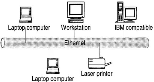
In this chapter we are going to focus on these three components in a computer network. But what is a computer network? A computer network is a distributed system consisting of loosely coupled computers and other devices. Any two of these devices, which we will from now on refer to as network elements or transmitting elements, without loss of generality, can communicate with each other through a communications medium. In order for these connected devices to be considered a communicating network, there must be a set of communicating rules or protocols each device in the network must follow to communicate with another in the network. The resulting combination consisting of hardware and software is a computer communication network, or computer network in short. Figure 1.1 shows a computer network.
The hardware component is made of network elements consisting of a collection of nodes that include the end systems commonly called hosts, intermediate switching elements that include hubs, bridges, routers, and gateways that, without loss of generality, we will call network elements.
available locally. The network elements, together with their resources, may be of diverse hardware technologies and the software may be as different as possible, but the whole combination must work together in unison.
Laptop computer
Work tation
B
IB
r
compatible
[image:23.459.121.378.131.268.2]Laser printer
Laptop computer
Figure 1.1 A Computer Network
Internetworking technology enables multiple, diverse underlying hardware technologies, and different software regimes to interconnect heterogeneous networks and bring them to communicate smoothly. The smooth working of any computer communication network is achieved through the low-level mechanisms provided by the network elements and high-level communication facilities provided by the software running on the communicating elements. Before we discuss the working of these networks, let us first look at the different types of networks.
1.2 Computer Network Models
Computer Network Fundamentals 5
elements and communication channels. The computers themselves may own their resources locally or may request resources from a remote computer. These computers are known by a string of names, including
host, client, or node. If a host has resources that other hosts need, then that host is known as a serve. Communication and sharing of resources are not controlled by the central computer but are arranged between any two communicating elements in the network. Figure 1.2 (a) and (b) show a centralized network model and a distributed network model respectively.
/ \
\
Surrogate PrinterSurrogate Computer
*rogate Laptop Surrogate Compl
Figure 1.2 (a) A Centralized Network Model
1.3 Computer Network Types
Computer networks come in different sizes. Each network is a cluster of network elements and their resources. The size of the cluster determines the network type. There are, in general, two main network types: the local area network (LAN) and a wide area network (WAN).
1.3.1
Local Area Network (LAN)
A computer network with two or more computers or clusters of
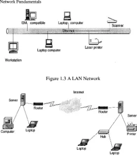
Computer Network Security proximity of the communicating elements, high-cost and quality communicating elements can be used to deliver better service and high reliability. Figure 1.3 shows a LAN network.
Computer
1
/
Mac IILaptop computer
Figure 1.2 (b) A Distributed Network Model
1.3.2 Wide Area Networks (WANs)
A wide area network (WAN), on the other hand, is a network made
Computer Network Fundamentals 7
IBM compatible
I
Laptop computerI
b
Laser printer [image:26.459.108.386.54.394.2]Workstation
Figure 1.3 A LAN Network
Figure 1.4 A WAN Network
1.3.3
Metropolitan Area Networks (MANs)
8 Computer Network Security
1.4 Data Communication Media Technology
The performance of a network type depends greatly on the transmission technology and media used in the network. Let us look at these two.
1.4.1 Transmission Technology
The media through which information is to be transmitted determine which signal to be used. Some media permit only analog signals. Some allow both analog and digital. Therefore depending on the media type involved and other considerations, the input data can be represented as either digital or analog signal. In an analog format, data is sent as
continuous electromagnetic waves on an interval representing things such as voice and video and propagated over a variety of media that may include copper wire, twisted coaxial pair or cable, fiber optics, or wireless. We will discuss these media soon. In a digital format, on the other hand, data is sent as a digital signal, a sequence of voltage pulses that can be represented as a stream of binary bits. Both analog and digital data can be propagated and many times represented as either analog or digital.
Transmission itself is the propagation and processing of data signals between network elements. The concept of representation of data for transmission, either as analog or digital signal, is called an encoding scheme. Encoded data is then transmitted over a suitable transmission
medium that connects all network elements. There are two encoding schemes, analog and digital. Analog encoding propagates analog
signals representing analog data such as sound waves and voice data. Digital encoding, on the other hand, propagates digital signals representing either an analog or a digital signal representing digital data of binary streams by two voltage levels. Since our interest in this book is in digital networks, we will focus on the encoding of digital data.
1.4.1.1 A n a l o g E n c o d i n g
of
D i g i t a l D a t aRecall that digital information is in the form of 1s or 0s. To send this information over some analog medium such as the telephone line, for example, which has limited bandwidth, digital data needs to be encoded using modulation and demodulation to produce analog signals. The encoding uses a continuous oscillating wave, usually a sine wave, with a constant frequency signal called a carrier signal. The carrier has three modulation characteristics: amplitude, fiequency, and phase shijl. The scheme then uses a modem, a modulation-demodulation pair,
Computer Network Fundamentals 9
three carrier characteristics or a combination. The resulting wave is between a range of frequencies on both sides of the carrier as shown below [I]:
Amplitude modulation represents each binary value by a different amplitude of the carrier frequency. The absence of or low carrier frequency may represent a 0 and any other frequency then represents a 1. But this is a rather inefficient modulation technique, and is, therefore, used only at low frequencies up to 1200 bps in voice grade lines.
Frequency modulation also represents the two binary values by two different frequencies close to the frequency of the underlying carrier. Higher frequencies represent a 1 and low frequencies represent a 0. The scheme is less susceptible to errors.
Phase shift modulation changes the timing of the carrier wave, shifting the carrier phase to encode the data. A 1 is encoded as a change of phase by 180 degrees and a 0 may be encoded as a 0 change in phase of a carrier signal. This is the most efficient scheme of the three and it can reach a transmission rate of up to 9600 bps.
1.4.1.2
Digital Encoding of Digital
Data
In this encoding scheme, which offers the most common and easiest way to transmit digital signals, two binary digits are used to represent two different voltages. Within a computer, these voltages are commonly 0 volts and 5 volts. Another procedure uses two representation codes:
nonreturn to Zero level (NRZ-L) in which negative voltage represents binary one and positive voltage represents binary zero; and nonreturn
to zero, invert on ones (NRZ-I). See Figures 1.5 and 1.6 for an example of these two codes. In NRZ-L, whenever a 1 occurs, a transition from one voltage level to another is used to signal the information. One problem with NRZ signaling techniques is the requirement of a perfect
synchronization between the receiver and transmitter clocks. This is, however, reduced by sending a separate clock signal. There are yet other representations such as the Manchester and differential Manchester, which encode clock information along with the data.
One may wonder why go through the hassle of digital encoding and transmission. There are several advantages over its cousin, analog encoding. These include:
Plummeting costs of digital circuitry
Computer Network Security Reduction of noise and other signal impairment because of use of repeaters
Capacity of channels is utilized best with digital techniques.
Better encryption and hence better security than in analog transmission.
000000000000001 11 1 1 11 1 1 100000000000000000001 1 I1 1110000000000000001 11 I1 1 I1
Figure 1.5 NRZ-L
Figure 1.6 NRZl
1.4.1.3
Multiplexing
of Transmission
Signals
Quite often during transmission of data over a network medium, the volume of transmitted data may far exceed the capacity of the medium. Whenever this happens, it may be possible to make multiple signal carriers share a transmission medium. This is referred to as
multiplexing. There are two ways in which multiplexing can be
achieved: time-division multiplexing (TMD) and frequency-division multiplexing (FDM).
Computer Network Fundamentals 11
extract the data signal for that channel in such a way that the bandwidths do not overlap. FDM has an advantage of supporting full- duplex communication.
TDM, on the other hand, works by dividing the channel into time slots that are allocated to the data streams before they are transmitted. At both ends of the transmission, if the sender and receiver agree on the time-slot assignments, then the receiver can easily recover and reconstruct the original data streams. So multiple digital signals can be carried on one carrier by interleaving portions of each signal in time.
1
A.2
Transmission Media
As we have observed above, in any form of communication there must be a medium through which the communication can take place. So network elements in a network need a medium in order to communicate. No network can function without a transmission medium because there would be no connection between transmitting elements. The transmission medium plays a vital role in the performance of the network. In total, characteristic quality, dependability, and overall performance of a network depends heavily on its transmission medium. The transmission medium also determines a network's capacity in realizing the expected network traffic, reliability for the network's availability, size of the network in terms of the distance covered, and the transmission rate. Network transmission media can be either wired or wireless.
1.4.2.1
Wired Transmission Media
Wired transmission media are used in fixed networks physically connecting every network element. There are different types of physical media, the most common of which are copper wire, twisted pair, coaxial cable, and optical fiber.
Copper wires have been traditionally used in communication because
of their low resistance to electrical currents which allows signals to travel even further. But copper wires suffer interference from electromagnetic energy in the environment, and because of this, they must always be insulated
Twisted pair is a pair of wires consisting of insulated copper wire
Computer Network
of radio frequency noises that may interfere with nearby cables and electronic components. To increase the capacity of the transmitting medium, more than one pair of the twisted wires may be bundled together in a protective coating. Because twisted pairs were far less expensive, easy to install, and had a high quality of voice data, they were widely used in telephone networks. However, because they are poor in upward scalability in transmission rate, distance, and bandwidth in LANS, twisted pair technology has been abandoned in favor of other technologies. Figure 1.9 shows a twisted pair.
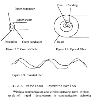
Coaxial cables are dual-conductor cables with a shared inner conductor
in the core of the cable protected by an insulation layer and the outer conductor surrounding the insulation. These cables are called coaxial because they share the inner conductor. The inner core conductor is usually made of solid copper wire, but at times also can be made up of stranded wire. The outer conductor, commonly made of braided wires but sometimes also made of metallic foil, or both, forms a protective tube around the inner conductor. This outer conductor is also further protected by another outer coating called the sheath. Figure 1.7 shows a coaxial cable. Coaxial cables are commonly used in television transmissions. Unlike twisted pairs, coaxial cables can be used over long distances. There are two types of coaxial cables: thinnet, a light and flexible cabling medium that is inexpensive and easy to install, and the thickent, which is thicker and harder to break and can carry more signals a longer distance than thinnet.
Optical fiber is a small medium made up of glass and plastics and
Computer Network Fundamentals
Core Cladding Inner conductor
Outer sheath
[image:32.459.80.377.62.378.2]Jacket
Figure 1.7 Coaxial Cable Figure 1.8 Optical Fiber
Figure 1.9 Twisted Pair
1.4.2.2
Wireless Communication
Wireless communication and wireless networks have evolved as a result of rapid development in communication technologies, computing, and people's need for mobility. Wireless networks fall one of the following three categories depending on distance as follows:
Restricted Proximity Network: This network involves
local area networks (LANs) with a mixture of fixed and wireless devices.
IntermediateIExtended Network: This wireless network
is actually made up of two fixed LANS components joined together by a wireless component. The bridge may be connecting LANS in two nearby buildings or even further.
Mobile Network: This is a fully wireless network connecting two network elements. One of these elements is usually a mobile unit that connects to the home network (fixed) using cellular or satellite technology.
Computer Network Security
Infrared: During an infrared transmission, one network element
remotely emits and transmits pulses of infrared light that carry coded instructions to the receiving network element. As long as there is no object to stop the transmitted light, the receiver gets the instruction. Infrared is best used effectively in a small confined area, within 100 feet, for example, a television remote communicating with the television set. In a confined area such as this, infrared is relatively fast and can support high bandwidths of up to 10 Mbps.
High-Frequency Radio: During a radio communication, high- frequency electromagnetic radio waves or radio frequency commonly referred to as RF transmissions are generated by the transmitter and are picked up by the receiver. Because the range of radio frequency band is greater than that of infrared, mobile computing elements can communicate over a limited area without both transmitter and receiver being placed along a direct line of sight; the signal can bounce off light walls, buildings, and atmospheric objects. RF transmissions are very good for long distances when combined with satellites to refract the radio waves.
Microwave: Microwaves are a higher frequency version of radio
waves but whose transmissions, unlike those of the radio, can be focused in a single direction. Microwave transmissions use a pair of parabolic antenna that produce and receive narrow, but highly directional signals. To be sensitive to signals, both the transmitting and receiving antennas must focus within a narrow area. Because of this, both the transmitting and receiving antennas must be carefully adjusted to align the transmitted signal to the receiver. Microwave communication has two forms: terrestrial when it is near ground and satellite microwave. The frequencies and technologies employed by these two forms are similar but with noted distinct differences.
Laser: Laser light can be used to carry data for several thousand yards
Computer Network Fundamentals
1.5
Network Topology
Computer networks, whether LANs, MANS, or WANs, are constructed based on a topology. The are several topologies including the following popular ones.
1.5.1 Mesh
A mesh topology allows multiple access links between network elements, unlike other types of topologies. The multiplicity of access links between network elements offers an advantage in network reliability because whenever one network element fails, the network does not cease operations; it simply finds a bypass to the failed element and the network continues to function. Mesh topology is most often applied in MAN networks. Figure 1.10 shows a mesh network.
Laptop
Figure 1.10 Mesh Network
1.5.2 Tree
Computer Network Security with each other. The functioning of the network as a unit is, therefore, fatally curtailed. Figure 1.1 1 shows a network using a tree topology.
Laptop Laptop
Figure 1.1 1 Tree topology
1.5.3 Bus
A more popular topology, especially for LANS, is the bus
Computer Network Fundamentals
Workstation Computer Lapt
Laptop
Laptop
Figure 1.12 Bus Topology
A collision control mechanism must also improve efficiency in the network using a bus topology by allowing only one element in the network to have control of the bus at any one time. That network element is then said to be the bus master and other elements are considered to be its slaves. This requirement prevents collision Erom occurring in the network as elements in the network try to seize the bus at the same time. A bus topology is commonly used by LANs.
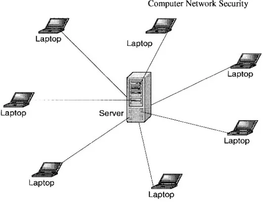
1.5.4 Star
Computer Network Security
[image:37.459.119.385.54.259.2]Laptop
Figure 1.13 Star Topology
1.5.5 Ring
Finally another popular network topology is the ring topology. In this topology, each computing element in a network using a ring topology is directly connected to the transmitting medium via a uni- directional connection so that information put on the transmission medium is able to reach all computing elements in the network through a mechanism of taking turns in sending information around the ring. Figure 1.14 shows a ring topology network. The taking of turns in passing information is managed through a token system. A token is a system-wide piece of information that guarantees the current owner to be the bus master. As long as it still owns the token, no other network element is allowed to transmit on the bus. When an element currently sending information and holding the token is finished, it passes the token downstream to its nearest neighbor. The token system is a good management system of collision and fairness.
There are variants of a ring topology collectively called hub hybrids
combining either a star with a bus or a stretched star as shown in Figure 1.15.
Computer Network Fundamentals 19
popular bus and star-based LAN topology is the Ethernet and the most popular ring-based LAN topology is the token ring.
Laptop
. .
Laptop
Figure 1.14 Ring Topology Network
1.6 Network Connectivity and Protocols
In the early days of computing, computers were used as stand-alone machines and all work that needed cross-computing was done manually. Files were moved on disks from computer to computer. There was, therefore, a need for cross-computing where more than one computer should talk to others and vice versa.
Laptop Laptop
Workstation
A new movement was, therefore, born. It was called the open system movement which called for computer hardware and software manufacturers to come up with a way for this to happen. But to make this possible, standardization of equipment and software was needed. To help in this effort and streamline computer communication, the International Standards Organization (ISO) developed the Open System Interconnection (OSI) model. The OSI is an open architecture model that functions as the network communication protocol standard, although it is not the most widely used. The TCP/IP model, a rival model to OSI, is the most widely used. Both OSI and TCP/IP models use two protocol stacks, one at the source element and the other at the destination element
1.6.1 Open System Interconnection (OSI) Protocol Suite
The development of the OSI model was based on the secure premise that a communication task over a network can be broken into seven layers where each layer represents a different portion of the task. Different layers of protocol provide different services and ensure that each layer can communicate only with its own neighboring layers. That is, the protocols in each layer are based on the protocols of the previous layers.
Starting from the top of the protocol stack, tasks and information move down from the top layers until they reach the bottom layer where they are sent out over the network media from the source system to the destination. At the destination the task or information rises back up through the layers until it reaches the top. Each layer is designed to accept work from the layer above it and to pass work down to the layer below it, and vice versa. To ease interlayer communication, the interfaces between layers are standardized. However, each layer remains independent and can be designed independently and each layer's functionality should not affect the functionalities of other layers above and below it. Table 1.1 shows an OSI model consisting of seven layers and the descriptions of the services provided in each layer.
Computer Network Fundamentals 21
from layer to layer of the sender machine, layer headers are appended to the data, causing the datagram to grow larger. Each layer header contains information for that layer's peer on the remote system. That information may indicate how to route the packet through the network, or what should be done to the packet as it is handed back up the layers on the recipient computer.
Layer Number
7 6
5
Protocol
Application Presentation Session
4
Table 1.1 I S 0 Protocol Layers and Corresponding Services Transport
2
Figure 1.16 shows a logical communication model between two peer computers using the I S 0 model. Table 1.2 shows the datagram with added header information as it moves through the layers. Although the development of the OSI model was intended to offer a standard for all other proprietary models, and it was as encompassing of all existing models as possible, it never really replaced many of those rival models it was intended to replace. In fact it is this "all in one" concept that led to market failure because it became too complex. Its late arrival on the market also prevented its much anticipated interoperability across networks.
Data Link
Machine B Machine A
3
I
ApplicationI
Network
1
Session
Phvsical
Datalink Datalink
Physical
Figure 1.16 I S 0 Logical Peer Communication Model
Computer Network
Network Data Link
No header Data
No header H 1 H2
Table 1.2 OSI Datagrams Seen in Each Layer with Header Added
1.6.2
Transport Control Protocol/Internet Protocol
(TCPIIP) Model
Data Data Data
Among OSI rivals was the TCP/IP, which was far less complex and more historically established by the time the OSI came on the market. The TCP/IP model does not exactly match the OSI model. For example it has two to three fewer levels than the seven layers of the OSI model. It was developed for the US Department of Defense Advanced Research Project Agency (DARPA) but over the years has seen a phenomenal growth in popularity and it is now the de facto standard for the Internet and many intranets. It consists of two major protocols: the transmission control protocol (TCP) and the Internet protocol (IP), hence the TCP/IP designation. Table 1.3 shows the layers and protocols in each layer.
Since TCP/IP is the most widely used in most network protocol suites by the Internet and many intranets, let us focus on its layers here.
Application Presentation Session
1.6.2.1 Application Layer
This layer, very similar to the application layer in the OSI model, provides the user interface with resources rich in application functions. It supports all network applications and includes many protocols on a data structure consisting of bit streams as shown in Figure 1.17.
1.6.2.2 Transport Layer
Computer Network Fundamentals 23
protocol (UDP). TCP provides a connection-oriented service and it
guarantees delivery of all application layer packets to their destination. This guarantee is based on two mechanisms: congestion control which throttles the transmission rate of the source element when there is traffic congestion in the network, and the flow control mechanism that tries to match sender and receiver speeds to synchronize the flow rate and reduce the packet drop rate. While TCP offers guarantees of delivery of the application layer packets, UDP, on the other hand, offers no such guarantees. It provides a no-frills connectionless service with just delivery and no acknowledgements. But it is much more efficient and a protocol of choice for real-time data such as streaming video and music. Transport layer delivers transport layer packets and protocols to the network layer. Figure 1.18 shows the TCP data structure and Figure 1.19 shows an UDP data structure.
1.6.2.3.
Network Layer
This layer moves packets, now called datagrams, from router to router along the path from a source host to the destination host. It supports a number of protocols including the Internet protocol (IP), Internet control message protocol (ICMP) and Internet Group Management Protocol (IGMP). The IP Protocol is the most widely
used network layer protocol. IP uses header information from the transport layer protocols that include datagram source and destination port numbers from IP addresses, and other TCP header and IP information, to move datagrams from router to router through the network. Best routes are found in the network by using routing algorithms. Figure 1.20 shows an IP datagram structure
I
Application header protocolsI
Bit streamFigure 1.17 Application Layer Data Frame
32 bits -4
Source address
I
Destination addressSequence number
I
Acknowledgement numberOther control information Data
Computer Network Security
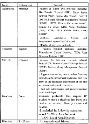
Protocols
-Handles all higher level protocols including: File Transfer Protocol (ITP), Name Server Protocol (NSP), Simple Mail Transfer Protocol (SMTP), Simple Network Management Protocol (SNMP), HTTP, Remote file access (telnet), Remote file server (NFS), Name Resolution (DNS), HTTP,- TETP, SNMP, DHCP, DNS, BOOTP
-Combines Application, Session and Presentation Layers of the OSI model.
- Handles all high level protocols
- Handles transport protocols including: Transmission Control Protocol (TCP), User Datagram Protocol (UDP).
-Contains the following protocols: Internet Protocol (IP), Internet Control Message Protocol (ICMP), Internet Group Management Protocol (IGMP).
- Supports transmitting source packets from any network on the internetwork and makes sure they arrive at the destination independent of the path and networks they took to get there.
- Best path determination and packet switching occur at this layer.
Contains protocols that require IP packet to cross a physical link from one device to another directly connected device.
-It included the following networks:
--
WAN-
Wide Area Network -- LAN - Local Area NetworkAll network card drivers.
Layer Application
Transport
Table 1.3 TCPIIP Protocol Layers
Delivery Unit Meessage
[image:43.459.103.397.67.477.2]Computer Network Fundamentals
Data
32 bits
.
Figure 1.19 An UDP Structure Source address
Other header control information
Other header control
Destination address UDP Checksum
Source port Destination Data
port number
number
1
1
Figure 1.20 An IP Datagram Structure
The standard IP address has been the so-called IPv4, a 32-bit addressing scheme. But with the rapid growth of the Internet, there was fear of running out of addresses, so a new IPv6, a 64-bit addressing scheme, was created. The Network layer conveys the network layer protocols to the data link layer.
1.6.2.4.
Data Link Layer
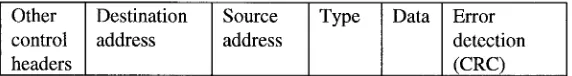
This layer provides the network with services that move packets from one packet switch like a router to the next over connecting links. This layer also offers reliable delivery of network layer packets over links. It is at the lowest level of communication and it includes the network interjace card (NIC) and operating system ( 0 s ) protocols. The protocols in this layer include: Ethernet, ATM and others such as frame relay. The data link layer protocol unit, theframe, may be moved over links from source to destination by different link layer protocols at different links along the way.
1.6.2.5.
Physical Layer
Computer Network Security
1.7 Network Services
For a communication network to work effectively, data in the network must be able to move from one network element to another. This only can happen if the network services to move such data work. For data networks these services fall into two categories:
Connection services to facilitate the exchange of data between the two network communicating end-systems with as little data loss as possible and in as little time as possible
Switching services to facilitate the movement of data from host to host across the length and width of the network mesh of hosts, hubs, bridges, routers, and gateways
1.7.1 Connection Services
How do we get the network transmitting elements to exchange data over the network? Two types of connection services are used: the
connected oriented and connectionless services.
1.7.1.1
Connected Oriented Services
With a connection-oriented service, before a client can send packets with real data to the server, there must be a three-way handshake. We will define this three-way handshake in later chapters.But the purpose of a three-way handshake is to establish a session before the actual communication can begin. Establishing a session before data is moved creates a path of virtual links between end systems through a network and, therefore, guarantees the reservation and establishment of fixed communication channels and other resources needed for the exchange of data before any data is exchanged and as long as the channels are needed. For example, this happens whenever we place telephone calls; before we exchange words, the channels are reserved and established for the duration. Because this technique guarantees that data will arrive in the same order it was sent in, it is considered to be reliable. In short the service offers:
Acknowledgments of all data exchanges between end- systems