Rochester Institute of Technology
RIT Scholar Works
Theses
5-2019
A Low-Cost Search-and-Rescue Drone Platform
Jonathan McClure
Jonathan McClure
A thesis submitted in partial fulfillment of the requirements for the Degree of Master of Science in Electrical Engineering
Supervised by Professor Dr. Ferat Sahin
Department of Electrical and Microelectronic Engineering Kate Gleason College of Engineering
Rochester Institute of Technology Rochester, New York
May 2019
Approved by:
Dr. Ferat Sahin, Thesis Advisor Date
Professor, Department of Electrical and Microelectronic Engineering
Dr. Raymond Ptucha, Committee Member Date
Assistant Professor, Department of Computer Engineering
Dr. Sohail Dianat, Committee Member Date
Department Head, Department of Electrical and Microelectronic Engineering
Dr. Sohail Dianat, Department Head Date
Department Head, Department of Electrical and Microelectronic Engineering
Acknowledgments
I would like to thank Dr. Ferat Sahin for serving as advisor. Without his support and guidance, this project would never have gotten off the ground.
I would also like to thank the members of the Multi-Agent Biorobotics Lab research group, especially Celal Savur, Shitij Kumar, and Anmol Modur, for their helpful feedback and advice. I am also grateful to Caleb Guillaume, Aaron Reckless, Chris Ugras, and Matthew Williams for their assistance with the testing process.
Finally, I would like to thank my family and friends for their enduring support and encouragement.
This thesis is dedicated to my parents. Thank you for all of your love and support, and for teaching me the value of hard work and perseverance.
Abstract
A Low-Cost Search-and-Rescue Drone Platform
Jonathan McClure
Supervising Professor: Dr. Ferat Sahin
In this work, an unmanned aerial system is implemented to search an outdoor area for an injured or missing person (subject) without requiring a connection to a ground operator or control station. The system detects subjects using exclusively on-board hardware as it traverses a predefined search path, with each implementation envisioned as a single element of a larger swarm of identical search drones. To increase the affordability of such a swarm, the system cost per drone serves as a primary constraint. Imagery is streamed from a camera to an Odroid single-board computer, which prepares the data for inference by a Neural Compute Stick vision accelerator. A single-class TinyYolo network, trained on the Okutama-Action dataset and an original Albatross dataset, is utilized to detect subjects in the prepared frames. The final network achieves 7.6 FPS in the field (8.64 FPS on the bench) with an 800x480 input resolution. The detection apparatus is mounted on a drone and field tests validate the system feasibility and efficacy.
• Assembly of a drone capable of autonomous flight and identification of persons on the ground, at a total cost less than the market entry price for conventional search-and-rescue drones.
• Implementation of entirely onboard, on-the-edge inferencing at data rates and resolutions beyond those of comparable systems.
• Creation and labelling of a custom dataset for identification of subjects in high-angle aerial photography.
• Successful field tests showing system capability of entirely autonomous detection of missing persons.
• J. McClure, F. Sahin, ”A Low-Cost Search-and-Rescue Drone for Near Real-Time Detection of Missing Persons,”System of Systems Engineer-ing (SoSE), 14th International Conference on, 2019. Accepted for pub-lication.
Contents
1 Introduction 1
2 Related Works 3
3 System Hardware 6
3.1 Drone Hardware . . . 6
3.2 Hardware for Onboard Detection of Subjects . . . 17
3.3 Summary . . . 22
4 System Software 24 4.1 SAR1 . . . 24
4.2 SAR2 . . . 27
4.3 SAR3 . . . 29
4.3.1 Dataset . . . 29
4.3.2 Training . . . 32
4.3.3 Deployment . . . 32
5 Results 33 5.1 Bench Testing . . . 33
5.1.1 Off-the-shelf model performance . . . 33
5.1.2 Custom Model Performance . . . 34
5.2 Field Testing . . . 34
5.2.1 SAR1 flight tests . . . 36
5.2.2 SAR2 flight tests . . . 38
5.2.3 Final flight tests . . . 41
6 Conclusions 46
7 Future Work 49
3.1 Motor and ESC . . . 7
3.2 Batteries . . . 8
3.3 Power diagram . . . 10
3.4 Onboard power circuitry . . . 10
3.5 Teensy wiring diagrams . . . 12
3.6 Teensy implementation . . . 12
3.7 Flight Controller . . . 14
3.8 3D Printer . . . 16
3.9 Complete drone (side view) . . . 17
3.10 Odroid and NCS . . . 18
3.11 GoPro mount . . . 20
3.12 Complete system (top view) . . . 21
3.13 Complete system (side view) . . . 22
4.1 Initial SAR1 code FSM . . . 25
4.2 Non-threaded vs threaded architecture . . . 26
4.3 SAR2 code FSM . . . 28
4.4 SAR2 flashing window method . . . 28
4.5 SAR3 code FSM . . . 30
4.6 Select images from training dataset . . . 31
5.1 Mission waypoints assigned for field testing . . . 35
5.2 Results from Solo flight of SAR1 test flights . . . 37
5.3 Results from Flight 1 of SAR2 test flights . . . 39
5.4 Select results from Flight 2 of SAR2 test flights . . . 40
5.5 Actors’ script for final flight test . . . 42
5.6 Select results from Flight 1 of Final test flights . . . 43
5.7 Select results from Flight 2 of Final test flights . . . 44
List of Tables
3.1 Final system implementation . . . 23
4.1 Learning rates for training . . . 32
5.1 Comparison of throughput for off-the-shelf networks . . . 33
5.2 Dijon throughput test results . . . 34
6.1 Proposed future implementation . . . 48
Introduction
Use of drones for search-and-rescue, surveillance, or related tasks typically requires that imagery recorded by the drone be streamed to a ground control station (GCS) for processing, with some associated latency. Alternatively, the imagery may be saved onboard the drone and retrieved for offline processing when the flight is complete [1]. The latter case introduces too much delay to be of use in a search-and-rescue application. Streaming solutions work well for a single drone [2]; however, when the number of drones is scaled up (such as in a search swarm [3]), the GCS may struggle to perform simultaneous inferencing on every stream. Depending on the hardware capabilities of the device, the demands of multiple agents could overwhelm the GCS, introducing inference latency issues or potentially even resulting in dropped frames. The data could be relayed to a distant processing station with more computing resources, but depending on the remoteness of the search area sufficient infrastructure may not be in place to facilitate this.
Implementations of deep learning networks at-the-edge must balance ac-curacy and throughput requirements against power consumption. In the same manner, the use of drones for search-and-rescue in large outdoor areas carries an intrinsic need for low power use, in order to maximize flight time and thus cover more search area [4]. The use of a vision accelerator such as the Movid-ius Neural Compute Stick (NCS) in conjunction with a single-board computer
CHAPTER 1. INTRODUCTION 2
has been shown to extend system capabilities while maintaining a low power profile and low cost [5]. The NCS thus presents an ideal means by which to im-plement onboard inferencing in a drone-based search-and-rescue application. Its small size and 1W power envelope [6] mean it can be deployed onboard a drone and used to perform inference on drone imagery, without significantly taxing system resources. This greatly reduces the quantity of information to be communicated to the GCS - rather than a continuous video feed, only the inference results need be transmitted. This reduces the stress upon the ma-chine, while also allowing its administrator, the Remote Pilot in Command (RPIC), to focus on other tasks rather than providing individualized oversight for each feed.
In this work, a NCS vision accelerator is used with a SBC aboard a low-cost, purpose-built drone. An object detection network running on the ac-celerator is used to detect subjects on the ground through imagery recorded onboard. The system is shown through field testing to provide a viable plat-form for the automated detection of missing persons in outdoor areas.
Related Works
In search-and-rescue scenarios, search teams are often forced to make use of helicopters or other aircraft to scout terrain for missing persons [7]. The operating costs for helicopters have been reported by various sources as ranging from $1600 to $16,500 per hour USD [8] [9]. The use of unmanned search aircraft such as drones may potentially result in a lower cost per search than the use of helicopters or search planes, in addition to decreasing the time required to find a subject [10].
The minimization of cost in drone design for search-and-rescue applications has been touched upon in the literature [11]. Reference [12] propose a ”smart” detection system to be mounted on a drone that utilizes passive infrared (PIR) sensors to detect humans. However, the range and field-of-view limitations of such sensors, as well as their inability to distinguish human triggers from animals, make them ill-suited for an outdoor search over a large area. A search-and-rescue drone was implemented by [13], but at a high unit cost and with a focus on interiors and small sites.
The literature extensively covers the path-planning aspects of search-and-rescue for drones [4], including multi-agent implementations [14]. In fact, [3] suggest as future work that such collaborative systems could be implemented onboard drones using SBCs. The findings of [15] suggest a Bluetooth
CHAPTER 2. RELATED WORKS 4
Energy LoRa modem may be used to connect SBCs across significant distances despite a low unit cost. To further extend the effective range of search drones, [16] propose and verify through simulation a method by which a master drone can relay messages to slave drones at great distances from the GCS. Means of notifying operators when subjects have been found by the search drone or drones are addressed by [17] and [2].
While the use of a thermal camera has been shown to improve subject de-tection rates [2], low-cost thermal solutions lack sufficient resolution to present enough detail for high-angle detection [18]. Additionally, no publicly acces-sible dataset of high-angle thermal imagery is available for use, meaning the functionality could not be trained into a detection network without requir-ing an extensive custom dataset. Aerial images present a high-angle, often oblique view of subjects on the ground [19]. Conversely, conventional pedes-trian datasets such as [20] feature subjects at approximately the same elevation as the camera. Further complications result from the small size (in pixels) of subjects in aerial imagery, compared to most pedestrian datasets in which the subjects appear much larger in proportion to the image size. A noteable excep-tion is the Okutama-Acexcep-tion dataset [21], featuring high-angle video sequences shot from drones and showing multiple actors in various poses.
Chapter 3
System Hardware
When selecting components with which to build the drone, cost had to be balanced with quality to ensure the system was not only inexpensive but also reliable and robust. Some components utilized here would not be recom-mended for use in future implementations, should another unit be constructed. Section 3.1 explores the components essential for flight of the drone itself, while Section 3.2 explores the peripherals required to implement the onboard miss-ing person detection system. Section 3.3 summarizes the hardware utilized and associated cost.
3.1
Drone Hardware
The drone utilizes brushless DC motors that provide sufficient thrust to support a total payload (components included) of at least 800g, with a recom-mended upper bound of 1600g. This wide range depends on such factors as battery voltage, atmospheric conditions, temperature, and other factors [28]. Four separate electronic speed controllers (ESCs) are utilized to provide com-pletely individualized three-phase control of each motor. Fig. 3.1 shows the mounting of these components on the frame arms. The ESC is not conven-tionally secured; instead, its wiring is snaked through the gaps in the arm and
Figure 3.1: A motor and ESC viewed from below.
the resulting friction holds it in place.
Dual 3-cell (3s) 1800mAh-capacity LiPo batteries, with discharge rate of 75C each, provide power for the various onboard systems at 11.1V nominal (11.4V actual when fully charged). The parallel combination of the batteries facilitates a peak discharge current of 270A. Each motor is capable of up to 15.1A current draw under duress. The flight controller and connected periph-erals require approximately 1.5A at boot and 1A in flight. The Odroid may require up to 6A current when preforming intensive computation, not includ-ing the approximately 500mA draw of the NCS. Therefore, the maximum total current needs of the system may thus be approximated as 68A - well below the maximum capacity supported.
There-CHAPTER 3. SYSTEM HARDWARE 8
Figure 3.2: While the parallel combination of two LiPo batteries extends the flight time of the system, a better solution for future implementations would be a single battery with a higher capacity.
fore, to provide insurance against undervoltage conditions and to permit mul-tiple consecutive flights without requiring the battery to be swapped, two batteries are instead mounted in parallel to effectively double the flight time of the system (Fig. 3.1). For future implementations, it is suggested that a single battery with a larger capacity be utilized, extending the possible flight time without the additional weight penalty associated with adding a second battery.
to be disconnected and the system powered down without requiring they be physically unplugged. The switch output is connected, in parallel, to a power distribution board (PDB), power module (PM), and universal battery elimi-nator circuit (UBEC). These are shown in Fig. 3.4. The PDB is simply used as the connection point for each of the ESCs, providing a direct connection to the 11.1V rail to drive the motors. The PM provides a clean 5V rail to the FC while supporting voltage and current monitoring of the batteries; the FC in turn routes that rail to the Teensy, GPS, and onboard telemetry and control radios. The UBEC provides another clean 5V rail for use by the Odroid and in turn the NCS. The isolation of the two 5V rails prevents load spikes due to the Odroid from adversely affecting the FC and other onboard components. Fig. 3.3 shows the different voltage rails present in the system.
A PixHawk Mini fulfills the role of flight controller (FC), aggregating data from the GPS, ESC feedback, and internal barometer and accelerometer to facilitate autonomous flight between waypoints. The unit was selected for its small footprint and low price point; its only limiting factor is the presence of only one UART port, whereas its full-size counterpart (the Pixhawk) has several available ports but a larger footprint and weight. The primary function of the UART port is to facilitate communicate with a ground control station (GCS) by sending MavLink messages via a telemetry radio.
CHAPTER 3. SYSTEM HARDWARE 10
Figure 3.3: System power flow and voltage rail diagram. Buses of the same color are referenced to the same voltage source and share a return path.
[image:19.612.199.421.430.623.2]buffer for the MavLink messages between the FC and GCS. If an incoming message from the Odroid were detected, then the next time the bus was quiet this message would be sent to the FC; essentially, the onboard computer thus mimics a GCS for the purpose of sending a command. The additional UART ports of the full-size Pixhawk would easily permit connections to secondary devices such as the onboard computer via an FTDI cable without requiring this man-in-the-middle; therefore, it is recommended over the Pixhawk Mini for future implementations in which the flight controller and onboard computer must interface with each other.
For this implementation, computer-to-FC communication support is im-plemented as proof of concept but not utilized in-flight. Instead, the UART GPIO of the computer are repurposed to pass an alarm control signal to the Teensy, which in turn utilizes it as the input for the drive circuitry of an opto-coupler (Fig. 3.5b). This provides isolated control of an alarm buzzer mounted below the frame, permitting the implementation of auditory feedback to indi-cate error conditions or successful detection of subjects.
CHAPTER 3. SYSTEM HARDWARE 12
[image:21.612.128.490.140.364.2](a) Serial man-in-the-middle (b) Alarm control
Figure 3.5: Teensy wiring diagrams
(a) A 3D-printed mount protects the Teensy while providing easy access to GPIO for prototyping.
(b) A 120dB alarm system (forward of battery) provides auditory feedback to the operator via the Teensy.
[image:21.612.129.322.426.603.2]current altitude, while increasing or decreasing the throttle out of the 40-60% ”dead zone” will cause the drone to ascend or descend correspondingly. The ”Auto” mode is characterized by essentially fully autonomous operation; the operator can control the yaw to rotate the drone if desired, but the roll, pitch, and throttle are entirely controlled by the autopilot. Auto mode will execute a series of commands stored as a ”mission”. Some pertinent commands em-ployed in this application include takeoff and landing sequences, navigation to waypoints, and timed loitering.
The Auto navigation mode is facilitated by the presence of an onboard GPS unit. The mode may only be utilized when the GPS has a connection to at least four satellites and the extended Kalman filter (EKF) utilized for position estimation has sufficiently stabilized. For best results, the GPS is mounted in a forward position such that nothing impedes its ”view” of the sky. The UBEC, PM, and batteries are placed as far away from the GPS unit as possible to reduce possible electromagnetic interference. A custom 3D-printed case and mount are utilized to secure and protect the unit. As care should be taken to avoid surrounding the unit with metal components that might potentially block RF signals, nylon screws are employed for mounting purposes (Fig. 3.7).
con-CHAPTER 3. SYSTEM HARDWARE 14
troller with fewer channels may instead be utilized, in order to reduce costs. If the antenna is allowed to dangle, it nearly touches the DC lines to the PM - an undesirable source of interference that has been observed to cause a loss of connection between the drone and controller. Thus, in order to reduce this noise, a mast is utilized to secure the receiver antenna and direct it upwards. To support monitoring of the drone flight systems, as well as uploading of waypoint coordinates, Mission Planner is utilized as the system GCS, running offboard on a laptop. It connects to the flight controller via the telemetry radio (note that in this implementation, all traffic is routed through the Teensy). If the drone loses the connection to the GCS, it will continue its flight regardless. However, if the drone loses its connection to the operator’s controller, it will return to its takeoff point and perform a landing there, in order to prevent potential flyways. This behavior is configurable, meaning operation completely independent of a ground station and ground operator connection is possible.
CHAPTER 3. SYSTEM HARDWARE 16
Figure 3.9: With both the main and secondary batteries and camera equipped, the drone measures a considerable 1.5kg. In future implementations, care should be taken to keep weight down in order to prolong flight time.
3.2
Hardware for Onboard Detection of Subjects
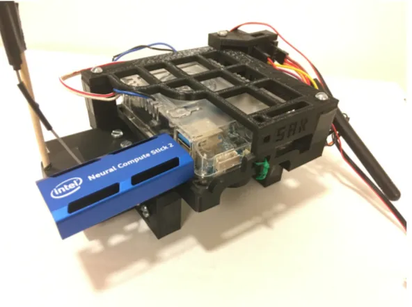
CHAPTER 3. SYSTEM HARDWARE 18
Figure 3.10: Odroid and NCS
An Intel Neural Compute Stick (NCS) vision accelerator is utilized to load the object detection network and perform inferences on images. Each NCS makes use of an embedded vision processing unit (VPU) for network calculations. The device is interfaced with through a USB port, with support for USB3 data transfer rates.
the device is only compatible with the OpenVINO toolkit. The NCSv2 is advertised as capable of up to eight times the performance of the NCSv1 [31]. As both the NCSv1 and NCSv2 are fanless, if the device experiences sig-nificant stress (such as high throughput or extended use), it is prone to over-heating. This can result in the connection between the Odroid and the device closing unexpectedly. While this issue has been observed extensively on the bench, under flight conditions the airflow over the device helps to cool it and reduce the risk of overheating. A similar problem manifests when the device becomes too cold, such as when performing extensive field testing in tempera-tures below freezing. Attaching air-activated hand warmers near the NCS has been observed to reduce or eliminate temperature-related device shutdowns in cold weather conditions.
A GoPro Hero 6 is utilized as the main onboard camera for the system, chosen for its integrated stabilization (eliminating the need for a gimbal) and durability. While the mount for the camera (Fig. 3.11) is rugged and reliable, it prevents access to the camera’s HDMI and USB ports. Therefore, the streaming capabilities of the camera over WiFi are exploited. A WiFi antenna module plugged into the USB2 port of the Odroid provides a connection to the wireless hotspot of the camera.
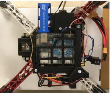
CHAPTER 3. SYSTEM HARDWARE 20
Figure 3.12: The 3D-printed mount architecture was designed to have as small a footprint as possible, in order to avoid interference with or risk of collision between the propellers and the devices.
CHAPTER 3. SYSTEM HARDWARE 22
Figure 3.13: The design is modular and compact, yet still facilitates airflow for cooling. In the event of a crash, the mounts are usually the first point of failure, absorbing the blow and protecting the other components.
3.3
Summary
Table 3.1: Final system implementation
Component Part Selection Cost
Frame DJI F450 kit $190 Motors DJI 2312e Inc. ESCs DJI 430 Lite Inc. Propellers DJI 9450 Inc. Battery Tattu 1800mAh 3s 75c LiPo (x2) $48 Radio Radiolink AT9S $106 Flight Controller 3DR Pixhawk Mini $160 GPS 3DR Micro M8N Inc. Telemetry Holybro Micro FPV Telemetry Inc. Power Module Holybro APM 10s $22 UBEC HENGE 6V 6A $14 SBC Odroid XU-4 $60 VPU Intel NCS2 $88 Camera GoPro Hero 6 Refurbished $280 Man-in-the-middle Teensy 3.1 $20
Chapter 4
System Software
Three main versions of the search-and-rescue (SAR) program were devel-oped, each with different objectives in mind. Section 4.1 explores the initial program, designed to implement off-the-shelf models with the NCSDK API. Section 4.2 explores the second iteration of the program, which attempts to compensate for weaknesses in these models through methods such as alternat-ing detection windows. Section 4.3 explores the final program, which utilizes a custom-trained model and the OpenVINO API and demonstrates superior recall and performance.
4.1
SAR1
The NCSDK API was installed on the Odroid and utilized for deployment of off-the-shelf pre-trained models from the Movidius Model Zoo [32]. Both TinyYolo [33] and a Mobilenet SSD [34] were explored. Frames are read at a constant, user-specified rate by the FFMPEG tool and logged locally. The program pulls the latest frame off the top of the stack, performs inference, and logs the results locally. The finite state machine (FSM) is shown in Fig. 4.1.
While this method is simple and effective, it results in unnecessary over-head on the Odroid. For bench testing purposes, an alternate method was
Figure 4.1: Initial SAR1 code FSM
CHAPTER 4. SYSTEM SOFTWARE 26
(a) Non-threaded architecture (entirely linear process)
[image:35.612.136.487.192.571.2](b) Threaded architecture (thread sur-rounded by dashed box)
4.2
SAR2
CHAPTER 4. SYSTEM SOFTWARE 28
Figure 4.3: SAR2 code FSM
[image:37.612.129.492.469.589.2]4.3
SAR3
The SAR3 program represents a substantial step forward from the previ-ous versions, introducing support for the OpenVINO API and thus allowing networks to be deployed on the NCSv2 as well as the NCSv1. The original streaming backend implementation through FFMPEG was modified to instead utilize Gstreamer, in an attempt to rectify issues with the GoPro stream when using the new OpenCV version required by this build.
Instead of an off-the-shelf network, this implementation makes use of a custom-trained, single-class TinyYolo network dubbed ”Dijon”. Dijon resizes the anchor boxes of a typical TinyYolo model [33] to achieve better convergence at the task of subject identification. The network utilizes an 800x480x3 input layer that reduces to a 25x15 grid, where each grid space proposes five anchor boxes. The 848x480 feed of the GoPro therefore can be fed almost directly into the network. While the 24 pixels at either edge of the frame are discarded, because they are already prone to being occluded by the drone legs when in flight, the information loss is negligible. Fig. 4.5 shows the FSM for the final implementation.
4.3.1 Dataset
CHAPTER 4. SYSTEM SOFTWARE 30
Figure 4.5: SAR3 code FSM
of labelled action data filmed with a drone [21].
Albatross
(a) Samples from Okutama-Action
(b) Samples from Albatross
CHAPTER 4. SYSTEM SOFTWARE 32
4.3.2 Training
[image:41.612.194.420.419.505.2]The network was trained using the Darknet framework via dual Nvidia Titan V GPUs. Firstly, a high-resolution 1280x720 network (”Cherry”) was trained on the dataset for 120,000 batches, using the Tiny YOLOv2 VOG weights for initialization. Next, the Cherry weights were used by a 800x480 network (”Mustard”) to perform transfer learning for 120,000 batches. Finally, the Mustard weights were trained for another 150,000 batches, resulting in the ”Dijon” network. For Dijon, Darknet dataset augmentation parameters such as saturation and hue variance were scaled to twice their typical values, thus subjecting the network to a wider variety of input images. The learning rates were updated in accordance with the schedule shown in Table 4.1.
Table 4.1: Learning rate hyperparameters for network training.
Iterations Learning Rate
Cherry Mustard Dijon
0 0.001 0.001 0.0001
50,000 0.0005 0.0005 0.00005
65,000 0.0001 0.0001 0.00001
80,000 0.00001 0.00001 0.000001
4.3.3 Deployment
Results
5.1
Bench Testing
5.1.1 Off-the-shelf model performance
[image:42.612.124.510.545.630.2]A threaded architecture is utilized to test the throughput of both the Mobilenet SSD and of TinyYolo on the NCSv1. The effects of using different devices and ports are explored, as summarized in Table 5.1. The inference time (Inf) is characteristic of the NCS itself, whereas the ”function” time (Func) takes into account the delay associated with transferring data on and off the device and is thus system-dependent. The data clearly demonstrate the superiority of the Odroid over the Raspberry Pi 3B used by Szankin [22] and Hochstetler et al. [27].
Table 5.1: Comparison of throughput for off-the-shelf networks
Task Pi 3B (USB2) Odroid (USB2) Odroid (USB3)
Time (ms) FPS Time FPS Time FPS Mobilenet Inf 88.32 11.32 88.32 11.32 88.32 11.32 Mobilenet Func 140.84 7.100 130.95 7.637 112.58 8.883
TinyYolo Inf 124.02 8.063 124.02 8.063 124.02 8.063 TinyYolo Func 223.70 4.470 205.49 4.866 165.61 6.038
CHAPTER 5. RESULTS 34
5.1.2 Custom Model Performance
[image:43.612.199.423.396.470.2]Table 5.2 shows the average bench performance of the Dijon network when tested with both versions of the NCS and both types of USB ports. The network is able to beat the best TinyYolo results from 5.1 despite having nearly twice the parameter count due to its larger input size (800x480 vs 448x448). Furthermore, it is shown in field tests to exhibit vastly improved recall and precision as compared to the off-the-shelf TinyYolo model. The network was also deployed using the NCSDK and NCSv1 and found to achieving 2.9637 FPS over USB3. This validates the advertised superior performance of the OpenVINO API over the older NCSDK.
Table 5.2: Dijon throughput test results Stick USB Port Latency (ms) FPS NCSv1 2.0 368.4170 2.7143 NCSv1 3.0 281.7030 3.5498 NCSv2 2.0 217.2030 4.6040 NCSv2 3.0 115.6840 8.6442
5.2
Field Testing
Figure 5.1: Mission waypoints assigned for field testing
CHAPTER 5. RESULTS 36
5.2.1 SAR1 flight tests
Field tests were performed on two separate occasions to explore the effec-tiveness of the off-the-shelf TinyYolo model with the SAR1 architecture. A fixed value of 5 FPS was utilized for the streaming rate.
Winter flight
A flight was attempted to explore the effects of a snowy backdrop on the detector recall. While conditions were windless, the temperature was near freezing, resulting in difficulties with the NCS becoming too cold and shutting down. These were initially addressed by attaching hand warmers to the frame near the device. The decision was made to fly regardless in order to accumulate video samples for offline analysis on the bench later. Shortly after the drone passed Waypoint 8 (Fig. 5.1), a complete power failure occurred and it fell some 15-20 feet out of the sky, bringing the test flight to a rapid end.
Solo flight
Figure 5.2: Results from Solo flight of SAR1 test flights
frames, only a single successful detection was observed with the TinyYolo network (Fig. 5.2, confidence 0.12356).
Outcome
CHAPTER 5. RESULTS 38
components to be swapped out without requiring a full mount reprint. It is suspected that some GPS and radio issues encountered later may be traced back to damage unknowingly sustained during the crash. The flight did yield video samples of subjects that later proved useful for bench testing.
Despite the underwhelming recall of the solo flight, the test was a major success in two regards. Firstly, it demonstrated the feasibility of an entirely autonomous search operation through the use of assigned waypoints as an autopilot mission. Secondly, it yielded excellent video of a human subject at altitude and angle desired for the final application. This footage would later be labelled and used to create the Albatross dataset (Section 4.3.1).
5.2.2 SAR2 flight tests
A field test was performed to test the performance of off-the-shelf TinyYolo with the SAR2 program. The same autopilot mission used for the SAR1 tests constituted the intended flight path. Two flights were attempted back-to-back; the first under cloudy but windless conditions, the second with occasional wind gusts. The NCSv1 was utilized for inference, achieving an average of 5.732 FPS on the 448x448 resolution network.
Flight 1
Figure 5.3: Results from Flight 1 of SAR2 test flights
Flight 2
CHAPTER 5. RESULTS 40
[image:49.612.125.496.126.319.2](a) Actor 1, Confidence 0.08558 (b) Operator, Confidence 0.14020
Figure 5.4: Select results from Flight 2 of SAR2 test flights
Outcome
the need for a more weather-proof enclosure for the Odroid and sensitive elec-trical components in future implementations.
5.2.3 Final flight tests
A final field test was undertaken to test the field performance of the Dijon network with the SAR3 program. The autopilot mission was assigned to the same ”key” flight path utilized in earlier tests (Fig. 5.1). Four actors were recruited to follow the paths and undertake the actions specified in Fig. 5.5. Two flights, with a short break between them, were performed around 8AM under clear and largely windless flight conditions. The NCSv2 was utilized for inference, achieving an average of 7.601 FPS on the 800x480 resolution network.
Flight 1
At the test site, the GPS was unable to achieve a satisfactory lock due to EKF variance. Therefore, the auto mode was not utilized, and the drone was instead flown under manual control by the operator, approximating the intended flight path. The system was able to successfully identify all four actors, as shown in Fig. 5.6, even with difficult background conditions such as glare and shadows from the early-morning sun.
CHAPTER 5. RESULTS 42
Figure 5.5: Actors’ script for final flight test
left, and thus appear slightly erroneous despite the successful performance of the network.
Flight 2
(a) Actor 1, Confidence 0.43872 (b) Actor 2, Confidence 1.0
(c) Actor 3, Confidence 0.29419 (d) Actor 3, Confidence 0.48975
[image:52.612.123.494.150.579.2](e) Actor 3, Confidence 0.50195 (f) Actor 4, Confidence 0.28735
CHAPTER 5. RESULTS 44
(a) Actors 1 and 2, Confidence 0.96875 (b) Actor 1, Confidence 0.26782
[image:53.612.123.496.111.401.2](c) Actor 2, Confidence 1.0 (d) Actor 2, Confidence 1.0
Figure 5.7: Select results from Flight 2 of Final test flights
battery was quickly swapped with a backup battery and the flight resumed. Thereafter, the system was able to successfully identify Actors 1 and 2, as shown in Fig. 5.7.
Outcome
Chapter 6
Conclusions
By the end of the testing process, the drone implemented here had suffered a number of failures and crashes. Most of these could be traced to operator error or to the use of faulty components that in future builds could easily be avoided. It is possible that the root cause of other issues could also be traced back to earlier crash events and mishaps. For example, the intermittent loss of flight controller communication is likely due to an incident early in the development process in which the last half inch of the antenna was chopped off by the propellers (due to ill-advised mounting and an unexpectedly sensitive throttle response). Therefore, while the system durability could theoretically present an issue in future implementations, a freshly assembled drone with new components would be unlikely to experience these issues.
If the specific unit implemented here were to be reused, several changes are recommended. It is suggested the cabling between the flight controller and radio be replaced, the radio antenna (or even the entire receiver and transmitter) replaced, the GoPro replaced with a hardwired camera, and the GPS mounted on a raised mast above the drone for improved signal quality. A single battery supported about 8-10 minutes flight time, and two batteries supported about 17 minutes; for increased flight time, the batteries should be replaced with a single high-capacity battery.
While the GoPro is not recommended for future implementations, it was an appropriate component selection for this proof-of-concept implementation. It is unlikely that many other cameras would have survived the abuse endured by the unit across the multiple rough landings and crashes associated with the development process. The main reason the GoPro is advised against is going forward is its seeming incompatibility with OpenCV 3 and 4 (which are required to make use of the OpenVINO API). This is despite the fact that the camera worked nearly flawlessly with OpenCV 2. It is possible that building the FFMPEG tool from the source might solve this problem, although the fact that the similar Gstreamer tool also proved an unreliable means of loading the stream suggests a deeper incompatibility.
CHAPTER 6. CONCLUSIONS 48 Table 6.1: Proposed future implementation
Component Part Selection Cost
Frame F450 clone $19 Motors DJI 2312e $99 ESCs DJI 430 Lite Inc. Propellers DJI 9450 Inc. Battery Tattu 4200mAh 3s 35c LiPo $48 Radio DXe DSMX 2.4Ghz Sport $90 Flight Controller Holybro Pixhawk 2.4.6 $180 GPS Holybro M8N Inc. Telemetry Holybro 100mW Telemetry Inc. Power Module Holybro APM 10s Inc. UBEC HENGE 6V 6A $14 SBC Odroid XU-4 $60 VPU Intel NCS2 $88 Camera Logitech C270 $40
Total $638
multiple classes could be implemented to permit the observation of wildlife or tracking of trespassing vehicles, as in [36].
Future Work
The most immediate possible extension of this work is the construction of a second drone and implementation of synchronized search of an area. Au-tomatic segmentation and traversal of a search polygon, similar to [1], could be implemented. Drone-to-drone communication should be considered. Once two drones have been implemented as proof-of-concept, the system may be scaled up to support a larger swarm.
The Dijon network recall, while impressive, could be further improved augmenting the Albatross dataset with more samples at various distances and angles, with actors in various clothing and positions. Additionally, negative samples that include camera noise and dense woods should be used, as these have been observed to trigger false positives. A secondary recurrent network could be implemented to wrap the output of the Dijon detector and distin-guish true positives from false positives. The use of multiple NCSv2 devices through a powered USB hub could be explored, as could the use of alternative accelerator solutions such as an Nvidia Jetson Nano.
Bibliography
[1] A. M. de Oca, L. Arreola, A. Flores, J. Sanchez, and G. Flores. Low-cost multispectral imaging system for crop monitoring. International Confer-ence on Unmanned Aircraft Systems (ICUAS), 2018.
[2] A. Rivera, A. Villalobos, J. Monje, J. Marinas, and C. Oppus. Post-disaster rescue facility: Human detection and geolocation using aerial drones. IEEE Region 10 Conference (TENCON), 2016.
[3] M. H. Dominguez, S. Nesmachnow, and J. Hernndez-Vega. Planning a drone fleet using artificial intelligence for search and rescue missions. InIEEE XXIV International Conference on Electronics, Electrical Engi-neering and Computing (INTERCON), 2017.
[4] S. Bernardini, M. Fox, and D. Long. Planning the behaviour of low-cost quadcopters for surveillance missions. In International Conference on Automated Planning and Scheduling (ICAPS), 2014.
[5] M. Modasshir, A. Quattrini Li, and I. Rekleitis. Deep neural networks: A comparison on different computing platforms. In 15th Conference on Computer and Robot Vision (CRV), 2018.
[6] S. Rivas-Gomez, A. Pena, D. Moloney, E. Laure, and S. Markidis. Explor-ing the vision processExplor-ing unit as co-processor for inference. 2018 IEEE International Parallel and Distributed Processing Symposium Workshops (IPDPSW), 2018.
[7] T. Heggie and M. Amundson. Dead men walking: Search and rescue in US National Parks. Wilderness and Environmental Medicine, 2009. [8] T. Sharples. Get into trouble outdoors - who pays for the rescue? Time,
2009.
[9] David McKie. Search and rescue for false alarms costs millions. CBC News, 2014.
[10] DJI, Black Channel, and EENA. Drone efficacy study - evaluating the impact of drones for locating lost persons in search and rescue events.
European Emergency Number Association (EENA), 2018.
[11] H. Saha, S. Basu, S. Auddy, R. Dey, A. Nandy, D. Pal, N. Roy, S. Jasu, A. Saha, S. Chattopadhyay, and T. Maity. A low cost fully autonomous gps (global positioning system) based quad copter for disaster manage-ment. In IEEE 8th Annual Computing and Communication Workshop and Conference (CCWC), 2018.
[12] R. Tariq, M. Rahim, N. Aslam, N. Bawany, and U. Faseeha. Dronaid: A smart human detection drone for rescue. In15th International Conference on Smart Cities: Improving Quality of Life Using ICT & IoT (HONET-ICT), 2018.
[13] S. Lee, D. Har, and D. Kum. Drone-assisted disaster management: Find-ing victims via infrared camera and lidar sensor fusion. 3rd Asia-Pacific World Congress on Computer Science and Engineering, 2016.
[14] G. Bevacqua, J. Cacace, A. Finzi, and V. Lippiello. Mixed-initiative plan-ning and execution for multiple drones in search and rescue missions. In
25th International Conference on International Conference on Automated Planning and Scheduling (ICAPS), 2015.
[15] L. Baumgrtner, A. Penning, P. Lampe, B. Richerzhagen, R. Steinmetz, and B. Freisleben. Environmental monitoring using low-cost hardware and infrastructureless wireless communication. In IEEE Global Humani-tarian Technology Conference (GHTC), 2018.
[16] S.A. Celtek, A. Durdu, and E. Kurnaz. Design and simulation of the hierarchical tree topology based wireless drone networks. InInternational Conference on Artificial Intelligence and Data Processing (IDAP), 2018. [17] Y. Ganesh, R. Raju, and R. Hegde. Surveillance drone for landmine detection. International Conference on Advanced Computing and Com-munications (ADCOM), 2015.
[18] H. Kayan, R. Eslampanah, F. Yeganli, and M. Askar. Heat leakage de-tection and surveiallance using aerial thermography drone. 26th Signal Processing and Communications Applications Conference (SIU), 2018. [19] T. Giitsidis, E.G. Karakasis, A. Gasteratos, and G. Ch. Sirakoulis.
BIBLIOGRAPHY 52
[20] P. Dollar, C. Wojek, B. Schiele, and P. Perona. Pedestrian detection: A benchmark. In The IEEE Conference on Computer Vision and Pattern Recognition (CVPR), 2009.
[21] M. Barekatain, M. Mart, H. Shih, S. Murray, K. Nakayama, Y. Matsuo, and H. Prendinger. Okutama-action: An aerial view video dataset for concurrent human action detection. In The IEEE Conference on Com-puter Vision and Pattern Recognition (CVPR) Workshops, 2017.
[22] M. Szankin, A. Kwaniewska, J. Ruminski, and R. Nicolas. Road condition evaluation using fusion of multiple deep models on always-on vision pro-cessor. InIECON 2018 - 44th Annual Conference of the IEEE Industrial Electronics Society, Oct 2018.
[23] D. Hou, T. Liu, Y. Pan, and J. Hou. AI on edge device for laser chip defect detection. In IEEE 9th Annual Computing and Communication Workshop and Conference (CCWC), 2019.
[24] Intel. Intel movidius myriad 2 vpu enables advanced com-puter vision and deep learning features in ultra-compact dji spark drone. 2017. https://www.movidius.com/news/ intel-movidius-myriad-2-vpu-enables-advanced-computer-vision -and-deep-learn.
[25] A. Boka and B. Morris. Person recognition for access logging. In IEEE 9th Annual Computing and Communication Workshop and Conference (CCWC), 2019.
[26] I. Lobachev, R. Maleryk, S. Antoschuk, D. Filiahin, and M. Lobachev. Integration of neural networks into smart sensor networks. In2018 IEEE 9th International Conference on Dependable Systems, Services and Tech-nologies (DESSERT), May 2018.
[27] J. Hochstetler, R. Padidela, Q. Chen, Q. Yang, and S. Fu. Embedded deep learning for vehicular edge computing. In 2018 IEEE/ACM Symposium on Edge Computing (SEC), Oct 2018.
[28] DJI. E305 user manual. http://dl.djicdn.com/downloads/e305/en/ E305_User_Manual_v1.00_en.pdf.
[30] Intel. Neural compute stick. https://software.intel.com/en-us/ movidius-ncs.
[31] Intel. Neural compute stick 2. https://software.intel.com/en-us/ neural-compute-stick.
[32] Movidius. Neural compute application zoo. https://github.com/ movidius/ncappzoo.
[33] J. Redmon and A. Farhad. Yolo9000: Better, faster, stronger. arXiv preprint arXiv:1612.08242, 2016.
[34] A. G. Howard, M. Zhu, B. Chen, D. Kalenichenko, W. Wang, T. Weyand, M. Andreetto, and H. Adam. Mobilenets: Efficient convolutional neural networks for mobile vision applications. arXiv preprint arXiv:1704.04861, 2017.
[35] thtrieu. Darkflow. https://github.com/thtrieu/darkflow.
[36] Susan Gawlowicz. Cracking down on poachers with imaging. 2019.https: //www.rit.edu/news/cracking-down-poachers-imaging.