1
PNEUMATICALLY POWERED LEGGED ROBOTS
G. MCLATCHEY, J. BILLINGSLEY
Faculty of Engineering and Surveying, University of Southern Queensland, West St, Toowoomba, QLD 4350, Australia
Legged Robots require actuators with a high power to weight ratio. Although pneumatic actuators do not perform well in this regard, they have other attractive characteristics which are useful in Legged Robots. This paper describes a mechanical solution for significantly improving the payload capacity of a robot powered with pneumatic cylinders, Robug IV, and reports on the theoretical design and experimental outcomes.
Keywords: Pneumatic cylinders, legged robots.
1. State of Pneumatically Powered Legged Robot Research.
The supporting legs of legged robots form part of multiple closed kinematic chains in which antagonistic forces pose a problem. Such a system is much better suited for force control, which can accommodate the over-constrained system [1], [2], [3], than position control where small errors can increase antagonistic forces [4], [5], [6].
Fluid based actuators such as hydraulics and pneumatics are ideally suited for force control, however they are less popular than electric motors because their natural compliance makes position control difficult and they are low in power density [2], [7].
Control of pneumatic cylinders has been advanced as much as possible by the authors’ work in Nested Loop Control [4], however, the inherent problem of low power to weight ratio remains. The most promising solution is to re-direct some of the torque available from the actuator to lift a leg into pushing the leg down to hold the body up. This has been implemented in Robot V but not investigated [8].
2. Design
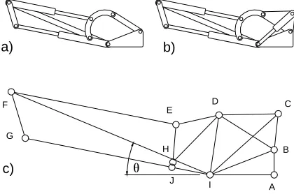
Figure 1a) shows the original Hip joint for Robug IV. Note the Hip actuator between points F and E and the Knee actuator (which is not considered further) between points G and I. The Hip on a Robug IV leg is the major load-bearing joint and must balance the largest force acting on the robot, which is its weight due to gravity. On uneven terrain the Abductor and Knee joints must provide higher torque to balance Robug’s weight, but a strategy of re-directing more torque in a particular direction is unsuitable since similar torque is required in both directions of joint movement.
The simplest way of re-directing torque is to use a spring element. The basic design of a spring inclusion is shown in Figure 1b). The original link between B and D is replaced with a plate that provides a spring mounting point
C. A tension spring stretches between points C and I, and provides a positive
[image:2.612.199.409.372.511.2]torque around the Hip axis at I. Please note that an identical spring and plate is provided on the other side of the Hip.
Figure 1. a) Robug IV Hip Joint, b) With Spring, c) Geometric Lengths and Angles Identified.
2.1. Modelling
Due to a simplification in the kinematic model of the Hip joint described in [9] and multiple errors in reproducing the equations, a more accurate kinematic model was derived by the first author for the Hip joint. Kinematic equations were also derived that describe the torque around I due to the spring extension. The force of the spring was modelled as:
G F
E
H
I D
A B C
a) b)
c)
1
1
( )
final length of spring
initial length of spring spring stiffness
minimum force to extend spring
f c
f
c
Force L L k F L
L k F
= − +
= = = =
2.2. Method of Determining Optimal Parameters
The new kinematic models for the Hip joint and spring were coded in Matlab. Design characteristics of the springs were matched to available springs that were thought to have adequate stiffness and be of suitable length for the dimensions of the leg. Preliminary findings resulted in a spring with twice the stiffness of the original being chosen. Final specs for the springs were Lc = 90 mm, k = 6.54 N/m and F1 = 58.86 N.
[image:3.612.181.425.383.595.2]Several experiments were conducted to determine the available lifting and downward torque of an unaltered Hip joint. Figure 2 shows the original lifting torque of the Hip joint at system air-pressure of 6 Bar.
Figure 2. Spring and Plate Design
modified by changing the spring support position, C, until the Design Torque was as close as possible to the original lifting torque without exceeding it anywhere along the range of θ. This ensured the maximum possible Spring Torque without reducing the resultant lifting torque below the Buffer (in this case the Buffer was set equal to 4 Nm).
Once the spring support position, C, was determined, a mild steel plate was made that replaced the original link BD and provided support for a mild steel shaft at C that the springs would be attached to (see Figure 1).
3. Results
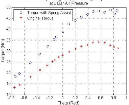
[image:4.612.179.427.387.589.2]The original and increased supporting torque can be observed in Figure 3. The increase in supporting torque due to the springs is substantial. At θ = 0 there is at least 36% more torque available to the Hip. From θ = 0.2 there is at least 40% more torque. Since the leg design is of the insect type, where the Knee is usually located above the Hip joint, the increase of supporting Hip torque for the useable range of θ≥ 0, is at least 36%.
Figure 3. Increase in Available Supporting Torque of Robug IV Hip Joint at 6 Bar Air-Pressure
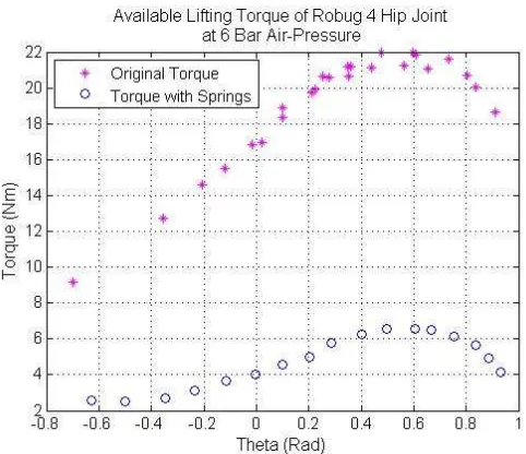
torque after adding springs. Lifting torque is drastically reduced, but remains above zero. This ensures the leg can still be lifted, although with an extended response time. In the preferred operating range of θ≥ 0 the minimum lifting torque is 4 Nm. Please note that the torque plotted in Figure 4 remains after the weight of the leg is accounted for.
Figure 4. Available Lifting Torque of Robug IV Hip Joint at 6 Bar Air-Pressure
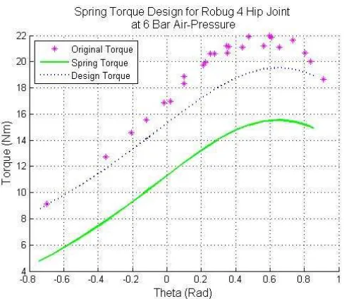
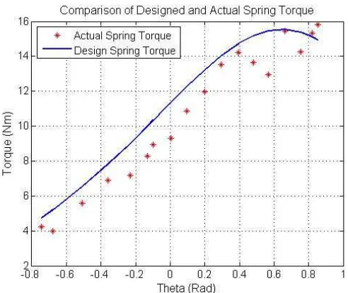
The designed and actual spring torque can be seen in Figure 5. The two are remarkably close, and promote confidence in the accuracy of the kinematic and computer models.
The weight of the new plates springs and shafts total 1.155 kg. Manufacturing the plates from aluminium will reduce the weight to 0.627 kg or less. Using hollow stainless steel shafts instead of solid mild steel would reduce weight further.
4. Observations
because only a small increase in the weight of the springs should be necessary over the current springs of lower stiffness.
Figure 5. Comparison of Designed and Actual Spring Torque
Increased friction due to the springs can be observed in some plots. Actual Spring Torque was close to but less than the Designed Spring Torque (see Figure 5). However, Figure 4 shows that the Lifting Torque with Springs is less than the Buffer of 4 Nm for θ < 0. This disparity can be explained by increased friction due to the large tangential force of the spring at pivots D and B. At most, this friction accounts for a loss of 2 Nm of torque. At higher system air-pressures this friction will increase, and may require a change of strategy from nylon bushes to bearings.
5. Conclusions
Redirecting some of the excessive lifting torque available to a pneumatically powered leg to assist in supporting the robot is feasible and very beneficial. An increase in supporting torque of 36% to well above 40% was found for the Robug IV Hip configuration.
Friction and stiction mitigation methods need to be investigated. These contributors will become more significant at higher system air-pressures. The importance of this discovery emphasises the need for implementation and experiment, not just theoretical analysis.
The performance of this system will improve with higher system air-pressures, provided the friction and stiction factors are reduced. Not only should higher air-pressure result in a more significant increase of supporting torque than 36%, but they should also experience decreased time for relocating a leg (since the lifting response time will be improved).
Increasing the power to weight ratio of pneumatic cylinders will significantly improve the performance of legged robots that incorporate them. Payload can be increased by the same percentage as the supporting torque increase, or extra equipment such as a pressure vessel and regulator could free pneumatically powered robots from their tether, making them much more mobile. Different gaits could also be possible along with corresponding increases in speed and stability.
6. Acknowledgment
The authors would like to extend their gratitude to the University of Southern Queensland (USQ) for funding this research.
7. References:
1. Zielinska, T., Synthesis of Control System - Gait Implementation
Problems. 4th International Conference on Climbing and Walking
Robots, 2001: p. 489.
2. Pratt, J., B. Krupp, and C. Morse, Series Elastic Actuators for High
Fidelity Force Control. Industrial Robot: An International Journal,
2002. 29(3): p. 234-241.
3. Colbrunn, R., G. Nelson, and R. Quinn. Modeling of Braided Pneumatic
4. McLatchey, G.J. and J. Billingsley. Force and Position Control Using
Pneumatic Cylinders. in 9th International Conference on Climbing and Walking Robots. 2006. Belgium.
5. Jiang, W.Y., A.M. Liu, and D. Howard. Foot-force Distribution in
Legged Robots. in 4th International conference on Climbing and Walking Robots. 2001.
6. Kar, D.C., Design of Statically Stable Walking Robot: A Review. Journal of Robotic Systems, 2003. 20(11): p. 671-686.
7. Cubero, S., Force, compliance and position control for a pneumatic
quadruped robot, in Faculty of Engineering. 1997, University of
Southern Queensland: Toowoomba.
8. Kingsley, D.A., A cockroach inspired robot with artificial muscles, in
Department of Mechanical and Aerospace Engineering. 2005, Case
Western Reserve University. p. 231.
9. Galt, S., Soft Computing Based Motion Control for an Eight Legged