BOBBIN FRICTION STIR WELDING OF AA1100
Submitted in accordance with the requirement of the University Teknikal Malaysia Melaka (UTeM) for the Bachelor Degree of Manufacturing Engineering (Hons)
by
MUHAMMAD IZZUDDIN BIN SHAMSHARHADI B051510023
940912-04-5261
UNIVERSITI TEKNIKAL MALAYSIA MELAKA
BORANG PENGESAHAN STATUS LAPORAN PROJEK SARJANA MUDA
Tajuk: BOBBIN FRICTION STIR WELDING OF AA1100
SesiPengajian: 2017/2018 Semester 2
Saya MUHAMMAD IZZUDDIN BIN SHAMSHARHADI (940912-04-5261)
Mengaku membenarkan Laporan Projek Sarjana Muda (PSM) ini disimpan di Perpustakaan Universiti Teknikal Malaysia Melaka (UTeM) dengan syarat-syarat kegunaan seperti berikut:
1. Laporan PSM adalah hak milik Universiti Teknikal Malaysia Melaka dan penulis.
2. Perpustakaan Universiti Teknikal Malaysia Melaka dibenarkan membuat salinan untuk tujuan pengajian sahaja dengan izin penulis.
3. Perpustakaan dibenarkan membuat salinan laporan PSM ini sebagai bahan pertukaran antara institusi pengajian tinggi.
4. *Silatandakan (√)
SULIT (Mengandungi maklumat yang berdarjah keselamatan atau kepentingan Malaysia sebagaimana yang termaktubdalam AKTA RAHSIA RASMI 1972)
TERHAD (Mengandungi maklumat TERHAD yang telah ditentukan oleh organisasi/ badan di mana penyelidikan dijalankan)
TIDAK TERHAD
Disahkan oleh:
________________________ ______________________________ AlamatTetap: Cop Rasmi:
ST 37 KM34 AIR HITAM DARAT
78300 MASJID TANAH MELAKA
DECLARATION
I hereby, declared this report entitled “BOBBIN FRICTION STIR WELDING OF AA1100” is the results of my own research except as cited in reference.
Signature :………
Author’s name : MUHAMMAD IZZUDDIN BIN SHAMSHARHADI
APPROVAL
This report is submitted to the Faculty of Manufacturing Engineering of UTeM as a partial fulfilment of the requirement for the degree of Bachelor of Manufacturing Engineering (Hons.). The member of the supervisor is as follow:
………..
i
ABSTRAK
ii
ABSTRACT
iii
DEDICATION
TO MY BELOVED PARENT,
Shamsharhadi Bin MohdSarif with Norazian Binti Mohd Salleh
For their supports in my whole life
TO MY HONOURED SUPERVISOR,
Dr. Mohammad Kamil Bin Sued
For his advices, support, motivation and patience during completion of this project
TO ALL STAFF & TECHNICIANS,
For their cooperation and advices during completion of this project
AND TO ALL MY COLLEAGUE,
For their encouragement, cooperation and effort in this study
iv
ACKNOWLEDGEMENT
In the name of Allah, the most gracious and merciful I would like to express my gratefulness as I managed to complete my undergraduate project for Bachelor Degree of Manufacturing Engineering within the time given. All thanks to Allah as only He can give the permission for me to complete this project.
My deep hearted appreciation goes to my supervisor Dr. Mohammad Kamil Bin Sued for all his guidance, ideas, thoughts and encouragements throughout the completion of the project. Thousands of thanks also I would like give to all UTeM staffs especially in Faculty of Manufacturing Engineering for their cooperation with me from starting of this project until the end.
v
TABLES OF CONTENTS
ABSTRAK ... i
ABSTRACT ... ii
DEDICATION ... iii
ACKNOWLEDGEMENT ... iv
TABLES OF CONTENTS ... v
LIST OF TABLES ... viii
LIST OF FIGURES ... ix
LIST OF ABBREVIATION ... xi
CHAPTER 1: INTRODUCTION 1.0 Background Study ... 1
1.1 Problem Statement ... 3
1.2 Objectives ... 4
1.3 Scope of Research ... 4
1.4 Project Significant ... 5
CHAPTER 2: LITERATURE REVIEW 2.0 Introduction ... 6
2.1 BFSW Working Principle ... 7
vi
2.1.2 Differences between Conventional Welding and BFSW ... 9
2.1.3 Types of Joining in FSW ... 10
2.2 Material Properties ... 11
2.2.1 General characteristic ... 11
2.3 Parameters Involved In BFSW ... 14
2.3.1 Tool design ... 14
2.3.2 Spindle and tool travel speed ... 17
2.3.3 Shoulder gap effects to the welding process ... 18
2.4 Area Affected By the Welding Process ... 19
2.5 Defects in FSW ... 20
2.5.1 Tunneling defect ... 20
2.5.2 Kissing bond ... 21
2.5.3 Void ... 21
2.6 FSW Applied in Industry ... 22
2.6.1 Marine ... 22
2.6.2 Aerospace ... 22
2.6.3 Automotive ... 23
2.7 Design of Experiment (DoE) ... 24
2.7.1 Taguchi Method ... 24
2.8 Conclusion ... 26
CHAPTER 3: METHODOLOGY 3.0 Introduction ... 27
3.1 Flowchart of Process ... 28
vii
3.2.1 The Cutting Process ... 29
3.2.2 Material Weldability ... 29
3.3 Selection of Process Parameter ... 30
3.3.1 Conventional milling machine parameter... 31
3.3.2 Tool fabrication ... 32
3.4 Design of Experiment (DoE) ... 33
3.5 Weld Response ... 34
3.6 Mechanical Test ... 35
3.6.1 Cutting of the welded sample ... 36
CHAPTER 4: RESULT AND DISCUSSION 4.0 Introduction ... 37
4.1 Temperature Measurement ... 38
4.2 Current Measurement ... 40
4.3 Vibration Measurement ... 42
4.4 Tensile Test Result ... 44
4.4.1 Optimization Parameter ... 46
CHAPTER 5: CONCLUSION AND RECOMMENDATION 5.0 Conclusions ... 49
5.1 Recommendations ... 50
REFERENCES ... 51
viii
LIST OF TABLES
Table 2. 1: Comparison between CFSW and BFSW 8
Table 2. 2 :Advantages of BFSW compared to Conventional Welding 10
Table 2. 3 :Wrought alloy composition 12
Table 2. 4 :1000 Series Aluminium Alloy’s composition 12
Table 2. 5 : Types of tool 15
Table 2. 6 : Experimental setup for Taguchi L9 Orthogonal Array 25
Table 3. 1 : Composition of Material AA1100 30
Table 3. 2 : Physical properties of AA1100 30
Table 3. 3 : Mechanical properties (sheet 0.2mm – 6.0mm, spec: BN EN 485-2:2008) 30 Table 3. 4 : Conventional milling machine specification 31
Table 3. 5 : Selected Machine Parameter 31
Table 3. 6 : Design of experiment constructed using Design Expert software 33 Table 3. 7 : List of devices used to measure the weld response 34
ix
LIST OF FIGURES
Figure 1. 1 : Differences between CFSW and BFSW 2
Figure 2. 1 : Schematic drawing of Friction Stir Welding 7 Figure 2. 2 : Backing anvil (a) backing anvil for CFSW and (b) backing anvil for BFSW 9
Figure 2. 3 : Types of welding joint 10
Figure 2. 4 : Type of tools 15
Figure 2. 5 : Different shoulder design 16
Figure 2. 6 : Types of pin/probe 16
Figure 2. 7 : Band pattern. Red circles indicated the band pattern in the SNZ 17 Figure 2. 8 : Graph of welding speed against tensile strength 18 Figure 2. 9 : Area affected by the heat input from the tool 19 Figure 2. 10 : Tunnel formation on welded material 20 Figure 2. 11 : Image under SEM microscope of the kissing bond formation 21
Figure 2. 12 : Void formation 22
Figure 2. 13 : Eclipse 5000 business jet 23
Figure 2. 14 : Honda Accord’ engine cradle 24
Figure 3. 1 : Flowchart of process 28
Figure 3. 2 : Conventional milling machine 31
Figure 3. 3 : Conventional lathe machine (MOMAC Mod.SM/200) 32
Figure 3. 4 : Tool designed with dimension 32
x
Figure 4. 1 : Configuration of thermocouple 38
Figure 4. 2 : Distance of each thermocouple on the plate 38
Figure 4. 3 : Current Graph at 80mm/min 40
Figure 4. 4 : Current Graph at 115mm/min 40
Figure 4. 5 : Current Graph at 155mm/min 41
Figure 4. 6 : Vibration at 80mm/min 42
Figure 4. 7 : Vibration at 115mm/min 42
Figure 4. 8 : Vibration at 155mm/min 43
Figure 4. 9 : Base material comparison with welded plate (UTS) 45 Figure 4. 10 : Failed formation at AS of the weld sample 45 Figure 4. 11 : ANOVA analysis of the experiments 46 Figure 4. 12 : Gradient B (travel speed) is higher than gradient A (spindle speed) 46 Figure 4. 13 : Parameter suggested by the Design Expert software 47
Figure 4. 14 : Percentage error calculation 47
xi
LIST OF ABBREVIATION
AA - Aluminium Alloy
AS - Advancing Side
ASTM - American Standard of Testing Material
BFSW - Bobbin Friction Stir Welding
CFSW - Conventional Friction Stir Welding
GMAW - Gas Metal Arc Welding
GTAW - Gas Tungsten Arc Welding
HAZ - Heat Affected Zone
MIG - Metal Inert Gas
Rpm - Revolution per minute
RSM - Response Surface Methodology
RS - Retreating Side
SZ - Stir Zone
TIG - Tungsten Inert Gas
TWI - The Welding Institute
TMAZ - Thermo-Mechanically Affected Zone
1
CHAPTER 1
INTRODUCTION
1.0 Background Study
Friction stir Welding (FSW) was invented at The Welding Institute (TWI), United Kingdom in 1991. It is an alternative method of joining technology process. FSW is
2
According to (Tanwar & Kumar, 2009), As a solid state process FSW eliminates many of the defects that usually occurred in fusion welding such as shrinkage, solidification cracking and porosity. Also, the bond between the two materials occurred uniquely of the original material, giving the welded material the comparable strength, bending and fatigue properties of the parent’s material. FSW is a new method that permanently joining metal in a greener way. This has been proven by Hassan et al, (2014) when an experiment was conducted between FSW and gas metal arc welding (GMAU). Both welding techniques were tested by welding pairs of 3mm thick aluminium strip. The parameter of each welding techniques was fixed and the aspects such as the welding quality, power input, macrostructure and microstructure of the welded joints were examined. Hence, the results obtained showed that the FSW was green, environment-friendly and more superior welding properties compared to the conventional GMAW.
FSW can be divided into two types. The classification is based on the tool design. Conventional Friction Stir Welding (CFSW) has one shoulder whereby Bobbin Friction Stir Welding (BFSW) has double shoulder. Figure below illustrates the differences between these two types of tool classification.
[image:17.612.169.447.432.567.2]According to (Alloy & Sheet, 2013), aluminium alloy AA1100 (1000 series Al alloys) composition consist of almost 99% aluminium. This material can’t be hardened through heat treatment and can only be hardened by cold working such as cold rolling etc. the material theoretically soften at room temperature after cold work and can archive a stable condition in a short period of time. In other words, the materials will cool down in a short time after being
3
worked. In welding area, this material has an excellent welding capability with all conventional methods nowadays and widely used to produce structural welds. The heat affected zones are also minimized when welding process is applied to this material. Furthermore, according to The Aluminium Association the 1000 series are classified under the non-heat-treatable alloys together with another two of its member such as 4000 series and 3000 series alloys. These alloys series also have an excellent weldability and high corrosion resistance when it comes to marine applications of the alloys. This makes the alloys generally used in the construction of buildings, pressure vessels, storages tanks etc.
This FSW technique is recommended to be applied in the industry and as for this research is to do the friction stir welding using the bobbin tool design for rolled aluminium AA1100. In addition, any common problem that usually occurred during the cooling down process at the welded joint such as cracking during solidification and porosity formation does not occur generally in FSW (Tabatabaeipour et al., 2016). This proves that FSW is way better in terms of possible number of problems that may occur can be minimized.
1.1 Problem Statement
4
will affect the internal structure of the material and also the strength of it. It is believe that when BFSW is adapted as a welding technique for joining aluminium alloy, the stated problem can be eliminated. The BFSW also currently have very limited study on the selected weld response and for AA1100. In addition, the study on BFSW also not having any clear guide line regarding the process setting.
1.2 Objectives
Objective of this work are as follows:
To measure weld response through measurement of vibration, current and temperature.
To evaluate weld performance through mechanical test.
To suggest optimum process parameter to weld the AA1100 using Response Surface Methodology (RSM).
1.3 Scope of Research
In the research on the Bobbin Friction Stir Welding of AA1100, there are a few constraints that have been decided. At the beginning of the research, the AA1100 need to be cut into a specific dimension (140mm X 140mm) using a shearing machine. The tool fabrication will be done by using conventional lathe machine. The material of the tool is made from H13 tool steel and will undergoing heat treatment process with 30 minutes soaking time at 1010oC and will be quenched by air blast. For the welding process, only spindle speed (rpm)
5
process itself. The weld performance will be tested its ultimate tensile strength using a tensile test machine. The sample of each weld will be cut into a dog bone shaped sample with the suitable American Standard of Testing Material(ASTM) standards before it is being tested. The results of the tensile then will be further optimized to find the optimum parameter using the Design of Experiment that has been selected.
1.4 Project Significant
a) This FSW is a new alternative way of joining techniques that can be possibly
being applied to the world of manufacturing industry especially. The cost of implementing this new way of joining technique maybe a bit high for the first time but it can be more reasonable after certain period of time because it only cost the company for the maintenance of the machine only not like the current situation where the wage of the welder with high skill also need to be paid.
b) This study is important to identify the successful of BFSW welding approach to
weld AA1100. The study will then be use as the foundation of technology transfer for the industry.
c) In current situation, there are very limited study in the selected field, this
6
CHAPTER 2
LITERATURE REVIEW
2.0 Introduction
The current welding techniques that commonly used nowadays are well established and proven to be able to weld almost every type of metals including the AA1100 alloys. Specifically in this field of study, AA1100 alloy are widely used in fabricating cookware product, chemical container, food industry containers, architectural flashing, lamp reflectors and as cable sheathing. In conjunction with that, there are several negative impacts that can occur to the external and internal properties of the welded product. Examples of the common defect are cracking formation, blow hole, porosity and shrinkage. In order to perform a perfect weld using these conventional techniques, some further attention need to be focused especially in the joint edge preparation, the need to immediately remove the oxide surface after the welding process, the proper selection on the filler metal used and the weld pool shield gas control. In addition, performing long and continuous welds using this conventional techniques can results in the distortion of the metal due to long period of the metal is being exposed to the high temperature. Hence, this problem needs another additional process in order to re-shape it to its original shape (Lafayette, 2017).
7
long and continuous weld while producing minimum amount of distortion with the results of high quality weld.
2.1 BFSW Working Principle
The BFSW consist of three main stages. The first is entering of tool where the tool is being forced to enter the workpiece at the area need to be joined. Second is dwell period which occurs after the entering stage where the tool rotates in a fixed place without any traverse along the workpiece, this is due to build up enough heat to plasticize the material before the tool traverse the workpiece. Last is the welding stages where the tool started to move traverse along the workpiece to join the two parts together (Ullegaddi, Murthy, Harsha, & Manjunatha, 2017). There is an additional stage according to (G.K Padly et al, 2017) which is the retracting/cooling stage. When the tool is at almost the end of the join area, the tool then levitated horizontally from the workpiece Figure 2.0 below shows how the tool operating on the workpiece (Kumar & Kailas, 2008).
[image:22.612.188.433.437.587.2]Basically, the principle of friction stir welding occurred in a solid state where the tool rotate the joining area into a below melting point of the material. The tool generates heat as the tool rotates and the mixing will began as the metal is heated by the heat pressure exerts by the
8
tool itself. There are two types of friction stir welding and it is categorized as conventional friction stir welding (CFSW) and bobbin friction stir welding (BFSW). The differences between these two types of tool are based on the number of shoulder it has. For CFSW only has one shoulder while BFSW has two shoulders.
2.1.1 Differences between CFSW and BFSW
[image:23.612.116.511.378.529.2]According to a research carried by (W. M. Thomas et al, 2015) the use of bobbin tool type (also known as self-reacting tool) has been proven to have more advantages compared to FSW. Table 2.1 below shows several differences between FSW and BFSW that has been concluded.
Table 2. 1: Comparison between CFSW and BFSW (M K Sued, 2015, P L Threadgill et al, 2009)
Conventional Friction Stir Welding (CFSW)
Bobbin Friction Stir Welding (BFSW)
Single shoulder Double shoulder, upper and lower
Require backing plate to perform weld and high clamping force of the tool
Use simple fixture to hold the weld material and less clamping force of the tool
Equipment need to be set up correctly to avoid damage while welding
Easy to assemble tool and require less set up time
9
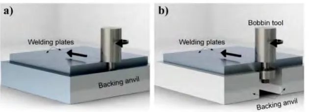
& Ma, 2005). Figure 2.2 shows the differentiation of backing anvil applied to FSW and BFSW. (Esmaily et al., 2016)
(Esmaily et al., 2016) has concluded in their study that BFSW shows more promising result instead of FSW. They had conducted an experiment on welding thick extruded AA6005-T6 profiles. There results obtained prove that BFSW is better than FSW when the peak temperature exerts by BFSW method is high with low heat input and having higher cooling rate compared to FSW. Furthermore, the microstructure formed in the stir zone of the BFSW happens to be finer than the microstructure formed in the stir zone of the FSW. Finer microstructure of the grain produced indicates that the material have higher hardness value and ultimate strength (Esmaily et al., 2016).
2.1.2 Differences between conventional welding and BFSW
[image:24.612.158.473.140.255.2]All types of conventional welding are under the fusion welding category, while BFSW is under the solid state welding. It has been observed that both of these welding categories use the different approach in order to join two or more material together. The difference is the fusion welding require the metal to reach the melting point to join the two metal together while the solid state welding achieve the same objective but by doing it under the melting point of the metal.