UNIVERSITI TEKNIKAL MALAYSIA MELAKA
DESIGN AND ANALYSIS OF THE SUSPENSION SYSTEM FOR
THE AGRICULTURAL SMART MOVER WITH USING
TOTAL DESIGN METHOD.
This report is submitted in accordance with the requirement of the Universiti Teknikal Malaysia Melaka (UTeM) for the Bachelor Degree of Mechanical
Engineering Technology (Automotives) with Honours.
by
MOHD SHAMSUL IZHAR BIN ABD RAHMAN B071410443
950525-08-6353
UNIVERSITI TEKNIKAL MALAYSIA MELAKA
BORANG PENGESAHAN STATUS LAPORAN PROJEK SARJANA MUDA
TAJUK: Design and Analysis of Suspension System for Agricultural Smart Mover with using Total Design Method
SESI PENGAJIAN: 2017/18 Semester 1
Saya MOHD SHAMSUL IZHAR BIN ABD RAHMAN
mengaku membenarkan Laporan PSM ini disimpan di Perpustakaan Universiti Teknikal Malaysia Melaka (UTeM) dengan syarat-syarat kegunaan seperti berikut:
1. Laporan PSM adalah hak milik Universiti Teknikal Malaysia Melaka dan penulis. 2. Perpustakaan Universiti Teknikal Malaysia Melaka dibenarkan membuat salinan
untuk tujuan pengajian sahaja dengan izin penulis.
3. Perpustakaan dibenarkan membuat salinan laporan PSM ini sebagai bahan pertukaran antara institusi pengajian tinggi.
4. **Sila tandakan ( )
SULIT
TERHAD
TIDAK TERHAD
(Mengandungi maklumat yang berdarjah keselamatan atau kepentingan Malaysia sebagaimana yang termaktub dalam AKTA RAHSIA RASMI 1972)
(Mengandungi maklumat TERHAD yang telah ditentukan oleh organisasi/badan di mana penyelidikan dijalankan)
Alamat Tetap:
3, Kampung Sungai Seluang,
Parit 7, 36750 Langkap,
Teluk Intan, Perak
Tarikh: ________________________
Disahkan oleh:
Cop Rasmi:
Tarikh: _______________________
DECLARATION
I hereby, declared this report entitled “Design and Analysis of Suspension System for Agricultural Smart Mover with using Total Design Method” is the results of my
own research except as cited in references.
Signature :
Author’s Name : Mohd Shamsul Izhar bin Abd Rahman
APPROVAL
This report is submitted to the Faculty of Engineering Technology of UTeM as a partial fulfillment of the requirements for the degree of Bachelor of Mechanical Engineering Technology (Automotive Technology) with Honours. The member of the supervisory is as follow:
i
ABSTRAK
Agricultural Smart Mover adalah sebuah kereta sorong biasa yang sudah dimodifikasi di mana padanya terdapat sistem enjin, sistem brek, dan sistem suspensi. Sistem suspensi memberikan banyak kebaikan kepada sesuatu kenderaan. Ia juga memastikan tayar dan jalan sentiasa bersentuhan seterusnya dapat mengekalkan keseimbangan kenderaan. Tajuk projek ini ialah rekabentuk dan analisis sistem suspensi untuk Agricultural Smart Mover. Antara langkah dalam penghasilan projek ini adalah mereka bentuk sistem suspensi yang sesuai dengan keadaan muka bumi di dalam ladang kelapa sawit supaya ia dapat mengurangkan impak yang diterima oleh Agricultural Smart Mover. Rekabentuk yang tepilih akan dianalisis dengan menggunakan CATIA V5 bagi menguji kekuatan rekebentuk itu sendiri.
ii
ABSTRACT
iii
DEDICATION
iv
ACKNOWLEDGEMENT
v
TABLE OF CONTENT
Abstrak ... i
Abstract ... ii
Dedication ... iii
Acknowledgement...iv
Table of Content...v
List of Tables...viii
List of Figures...ix
CHAPTER 1: INTRODUCTION ... 1
1.0 Introduction ... 1
1.1 Problem Statement ... 3
1.2 Objective ... 4
1.3 Work Scope ... 4
CHAPTER 2: LITERATURE REVIEW ... 5
2.0 Introduction. ... 5
2.1 History of Suspension. ... 6
2.2 Main Components of Modern Suspension System. ... 7
2.3 Spring Design ... 10
2.3.1 Type of Springs ... 11
2.4 Type of Suspension ... 15
2.4.1 Car Suspension ... 15
vi
CHAPTER 3: METHODOLOGY ... 24
3.0 Overview ... 24
3.1 Software of Designing Method ... 25
3.2 Flow Chart ... 26
3.3 Market Study. ... 26
3.4 Literature Review ... 28
3.5 Product Requirements. ... 29
3.5.1 Product Design Specification... 29
3.5.2 Material Selection ... 29
3.6 House of Quality ... 31
3.7 Conceptual Design. ... 32
3.8 Selection Method ... 33
3.8.1 Morphological Chart. ... 33
3.8.2 Analysis Based Selection ... 34
3.9 Final Concept. ... 34
3.9.1 Analysis on Agriculture Smart Mover Bodywork ... 34
3.9.2 CATIA V5 Modelling Software... 34
3.9.3 Finite Element Analysis ... 35
CHAPTER 4: RESULTS AND DISCUSSION ... 36
4.1 Introduction ... 36
4.2 Initial Result ... 36
4.3 Suspension Design ... 36
4.3.1 Software ... 36
4.3.2 Arm Design ... 37
4.3.3 Design Characteristics ... 38
4.4 Material Selection ... 39
4.5 Arm Analysis ... 39
4.6 Selected Arm Design ... 42
4.7 Assembly Simulation Result ... 42
4.7.1 SolidThinking ... 42
vii
CHAPTER 5: CONCLUSION AND FUTURE WORK ... 48
5.1 Introduction ... 48
5.2 Summary ... 48
5.3 Significance ... 48
5.4 Future Work ... 49
REFERENCES. ... 50
APPENDICES ... 52
a. Material Properties...52
viii
LIST OF TABLES
Table 2.1: Various type of leaf spring ... 13
Table 3.1: Product benchmarking ... 27
Table 3.2: Product requirements. ... 29
Table 3.4: 4 Conceptual design. ... 32
Table 3.5: Morphological Chart ... 33
Table 4.1: Arm designs ... 37
Table 4.2: Design parameters ... 38
Table 4.3: Design 1 analysis ... 39
Table 4.4: Design 2 analysis ... 40
ix
LIST OF FIGURES
[image:13.612.137.519.198.408.2]Figure 1.1: 2nd class lever. ... 2
Figure 2.1 Spring extensions and compression. ... 7
Figure 2.2: Bushings. ... 9
Figure 2.3: Torsion Bar suspension. ... 14
Figure 2.4: Hierarchy of popular suspension types. ... 15
Figure 2.5: Air spring. ... 17
Figure 2.6: Macpherson Assembly. ... 18
Figure 2.7: Double Wishbone suspension. ... 19
Figure 2.8: 1968 BMW R60US with conventional telescopic fork ... 21
Figure 2.9: Girder fork. ... 22
Figure 2.10: Yamaha TZM Mono-shock. ... 22
Figure 2.11: Swingarm installed in Honda EX5 ... 23
Figure 3.1: Flow Chart. ... 26
Figure 4.1: Suspension Assembly ... 43
Figure 4.2: Von Mises Stress ... 43
Figure 4.3: Shear stress ... 44
Figure 4.4: Tension & Compression ... 45
Figure 4.5: Displacement ... 46
1
CHAPTER 1
INTRODUCTION
1.0 Introduction
According to Lewis (1994), wheelbarrow is a small hand-propelled vehicle, usually with just one wheel, designed to be pushed and guided by a single person using two handles at the rear, or by a sail to push the ancient wheelbarrow by wind. Wheelbarrow term itself contains two words, which are ‘wheel’ and ‘barrow’. The derivation of bearwe(old English) produced ‘barrow’. Bearwe was a carrying loads device during that time.
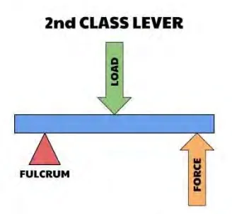
2 Figure 1.1: 2nd class lever.
The Agriculture Smart Mover actually is the improvised version of the typical wheelbarrow which it has suspension system to support the loads in the carriage. For it to be more applicable in the plantation, suspension is also added aside from braking system and engine powertrain.
Gillespie (1992) states that suspension system consists of spring, damper and structural components carrying the sprung mass (car chassis). The suspension system serves two main purposes that contributes to the car’s handling and braking. It also protecting the vehicle itself and any cargo from damage at the same time.
3 1.1 Problem Statement
Demand in palm oil is relatively high nowadays. It even started to make huge profit and contribution to Malaysia’s economy in 2009 where as stated in Utusan Online. Tan Sri Bernard Dompo, Minister of Plantation Industries and Commodities, said that the profit increases from RM52.7b in 2009 to RM125b in 2011.
In yesteryear’s February 9th, Irawati Hamdany reported in kelapasawitnews.com that Malaysia's palm oil production is expected to increase. While oil production in the world today is more than 55 million tons, Malaysia produces more than 21 million tonnes. Malaysia and Indonesia become a country that controls the world's palm oil production.
These two news shows that the high need in palm oil. Developments in palm oil industry should be able to fill the demands. The use of normal wheelbarrow has been applied for over the years in order to move the collected fruits from the tree to fruit collection point before the fruit transports to factory.
. The existing wheelbarrow are not durable due to the maximum weight of the palm oil fruit. The wheelbarrow will receive the force exerted on it and the high force will damage the wheelbarrow. The uneven or bump on off-road surface condition in the plantation also will affect the wheelbarrow durability.
4 1.2 Objective
The objective of this project is:
1. To design a suspension for the agriculture smart mover with using total design method.
2. To analyse the suspension system with using suitable simulation software.
1.3 Work Scope
i) This project will cover only in designing and selecting the suspension, and then the design will go through further fabrication work.
5
CHAPTER 2
LITERATURE REVIEW
2.0 Introduction.
In this chapter, a brief history of suspension will be cited. Various types of suspension are available in the market nowadays. The suspension that will be covered in this chapter ranging from motorcycle’s to car’s suspension system.
Gillespie (1992) states that suspension system consists of spring, damper and structural components carrying the sprung mass (car chassis). The springs provide cushioning with absorbing impacts when a wheel hits a bunp in the road. It also keep the control of vehicle by keeping the wheels in contact with the road while resisting wheel’s movement and rebounds, pushing the wheel back down.
6 2.1 History of Suspension.
According to Subramani (2016) an early form of suspension on ox-drawn carts had the platform swing on iron chains attached to the wheeled frame of the carriage. Until the turn of the 19th century, this system remained the basis for all suspension systems, although the iron chains were replaced with the use of leather straps by the 17th century.
Automobiles were initially developed as self-propelled versions of horse-drawn vehicles. However, horse-horse-drawn vehicles has relatively slow speeds, and their suspension was not well suited to the higher speeds permitted by the internal combustion engine. That is why the earlier suspension systems are not suitable for modern vehicles.
Adam (1837) said that in is writing that Obadiah Elliott registered the first patent for a spring-suspension vehicle; - each wheel had two durable steel leaf springs on each side and the body of the carriage was fixed directly to the springs, which were attached to the axles. Within a decade, most British horse carriages were equipped with springs; wooden springs in the case of light one-horse vehicles to avoid taxation, and steel springs in larger vehicles. These were often made of low-carbon steel and usually took the form of multiple layer leaf springs.
7 2.2 Main Components of Modern Suspension System.
At this point, it is important to understand that the main components of a moving vehicle suspension system are the struts, shock absorbers, springs, and tires,
Reza (2008).The springs support the weight of the vehicle, maintain ride height, and
absorb road shock. Springs are the flexible links that allow the frame and the body to ride relatively undisturbed while the tires and suspension follow the bumps in the road.
Springs are the compressible link between the frame and the body. When an additional load is placed on the springs or the vehicle meets a bump in the road, the springs will absorb the load by compressing. The springs are a very important component of the suspension system that provides ride comfort. Shocks and struts help control how fast the springs and suspension are allowed to move, which is important in keeping tires in firm contact with the road.
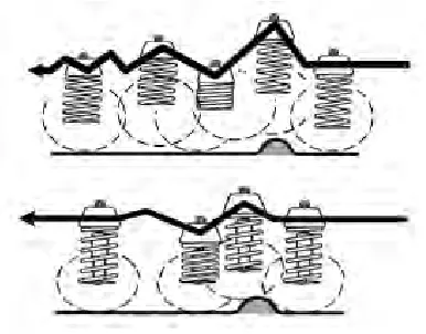
[image:20.612.228.421.483.634.2]During the study of springs, the term bounce refers to the vertical (up and down) movement of the suspension system. The upward suspension travel that compresses the spring and shock absorber is called the jounce, or compression. The downward travel of the tire and wheel that extends the spring and shock absorber is called rebound, or extension.
8 When the spring is deflected, it stores energy. Without shocks and struts the spring will extend and release this energy at an uncontrolled rate. The spring's inertia causes it to bounce and overextend itself. Then it re-compresses, but will again travel too far. The spring continues to bounce at its natural frequency until all of the energy originally put into the spring is used.
If the struts or shock absorbers are worn and the vehicle meets a bump in the road, the vehicle will bounce at the frequency of the suspension until the energy of the bump is used up. This may allow the tires to lose contact with the road.
Struts and shock absorbers that are in good condition will allow the suspension to oscillate through one or two diminishing cycles, limiting or damping excessive movement, and maintaining vertical loads placed upon the tires. This helps keep the tires in contact with the road.
By controlling spring and suspension movement, components such as tie rods will operate within their design range and, while the vehicle is in motion, dynamic wheel alignment will be maintained.
Bushings.
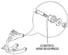
9 Figure 2.2: Bushings.
As with all suspension system components, control arm bushings are dynamic components, meaning that they operate while the vehicle is in motion. Control arms act as locators because they hold the position of the suspension in relation to the chassis. They are attached to the vehicle frame with rubber elastomeric bushings. During suspension travel, the control arm bushings provide a pivot point for the control arm. They also maintain the lateral and vertical location of the control arm pivot points, maintain dynamic wheel alignment, and reduce transmitted noise, road shock, and vibration, while providing resistance to suspension movement.
During suspension travel the rubber portion of the bushing must twist to allow control arm movement. Control arm bushings that are in good condition act as a spring; that is, the rubber will spring back to the position from which it started. This twisting action of the rubber will provide resistance to suspension movement.
As previously stated, control arm bushings are dynamic suspension components. As the control arm travels through jounce and rebound, the rubber portion of the bushing will twist and stretch. This action transfers energy into the bushing and generates heat.
10 Rubber bushings must not be lubricated with petroleum-based oil. A petroleum-based product will destroy the bushings. Instead, use a special tire rubber lubricant or a silicone based lubricant.
Worn suspension bushings allow the control arm to change positions. This results in driveline vibration (primarily rear wheel drive rear control arm bushings), dynamic alignment angle changes, tire wear, and handling problems. Control arm bushing wear (looseness) will create a clunking sound while driving over rough roads.
2.3 Spring Design
Before discussing spring design, it is important to understand sprung and unsprung weight. Sprung weight is the weight supported by the springs. For example, the vehicle's body, transmission, frames, and motor would be sprung weight. Unsprung weight is the weight that is not carried by springs, such as the tires, wheels, and brake assemblies.
11 2.3.1 Type of Springs
Coil Springs
The most commonly used spring is the coil spring. The coil spring is a length of round spring steel rod that is wound into a coil. Unlike leaf springs, conventional coil springs do not develop inter-leaf friction. Therefore, they provide a smoother ride.
The diameter and length of the wire determine the strength of a spring. Increasing the wire diameter will produce a stronger spring, while increasing its length will make it more flexible.
Spring rate, sometimes referred to as deflection rate, is used to measure spring strength. It is the amount of weight that is required to compress the spring 1 inch. For example: If it takes 100 lbs. to compress a spring 1 inch, it would take to 200 lbs. to compress the spring 2 inches.
Some coil springs are made with a variable rate. This variable rate is accomplished by either constructing this spring from materials having different thickness or by winding the spring so the coil will progressively compress at a higher rate. Variable rate springs provide a lower spring rate under unloaded conditions offering a smoother ride, and a higher spring rate under loaded conditions, resulting in more support and control.