UNIVERSITI TEKNIKAL MALAYSIA MELAKA
DESIGN OF LABORATORY INFORMATION AND
MANAGEMENT SYSTEM
This report is submitted in accordance with requirement of the Universiti Teknikal Malaysia Melaka (UTeM) for the Bachelor Degree of Manufacturing Engineering (Robotics and
Automation) with Honours.
By
RAZAKUAN BIN ABD RAHMAN
FACULTY OF MANUFACTURING ENGINEERING
UNIVERSITI TEKNIKAL MALAYSIA MELAKA
BORANG PENGESAHAN STATUS LAPORAN PROJEK SARJANA MUDA
TAJUK: DESIGN OF LABORATORY INFORMATION AND MANAGEMENT
SYSTEM
SESI PENGAJIAN: 2014/15 Semester 2
Saya RAZAKUAN BIN ABD RAHMAN
mengaku membenarkan Laporan PSM ini disimpan di Perpustakaan Universiti Teknikal Malaysia Melaka (UTeM) dengan syarat-syarat kegunaan seperti berikut: 1. Laporan PSM adalah hak milik Universiti Teknikal Malaysia Melaka dan penulis. 2. Perpustakaan Universiti Teknikal Malaysia Melaka dibenarkan membuat salinan
untuk tujuan pengajian sahaja dengan izin penulis.
3. Perpustakaan dibenarkan membuat salinan laporan PSM ini sebagai bahan pertukaran antara institusi pengajian tinggi.
4. **Sila tandakan ( )
SULIT
TERHAD
TIDAK TERHAD
(Mengandungi maklumat yang berdarjah keselamatan atau kepentingan Malaysia sebagaimana yang termaktub dalam AKTA RAHSIA RASMI 1972)
(Mengandungi maklumat TERHAD yang telah ditentukan oleh organisasi/badan di mana penyelidikan dijalankan)
Alamat Tetap:
NO. 134 JALAN BIRU 7
FELDA PENGELI TIMUR, 81440 BANDAR TENGGARA, JOHOR
Tarikh: ________________________
Disahkan oleh:
Cop Rasmi:
APPROVAL
This report is submitted to the Faculty of Manufacturing Engineering of UTeM as a partial fulfillment of the requirements for the degree of Bachelor of Manufacturing Engineering (Robotics & Automation) (Hons.). The member of the supervisory is as follow:
DECLARATION
I hereby, declared this report entitled “Design of Laboratory Information and Management System” is the results of my own research except as cited in
references.
Signature : ………..
Author’s Name : RAZAKUAN BIN ABD RAHMAN
ABSTRACT
Industrial drive are used extensively throughout the manufacturing industry. However, there is some issue related to the management of the industrial drive components in the industry. One of the issue is the use of various form in the management of industrial drive components. This conventional approach consume a lot of time and sometimes difficult to track the data information of the industrial drive components. Many systems had been introduced to manage the components in a various ways. The main idea of this project is to propose the appropriate management system of the industrial drive components. The proposed management system will focus on the industrial drive components available at fluid power laboratory. The project will be known as the Laboratory Information and Management System (LIMS). This system focuses on recording and updating the data of industrial drive components. This new system also used database concept to store all the information. This system will help staff to arrange information faster and easier to allow them to focus on other work. The development of this system involves the use of Visual Basic for Application (VBA) for Graphical User Interface (GUI), Microsoft database access, and CATIA as a design software. All the components will be design in 3D for future purpose and linked by VBA through the GUI. This project is expected to provide all the data management and information which can be stored in a database system where the user can easily locate the components. This system will give a better performance in storing the components information without having do it manually.
ABSTRAK
Pemacu industri digunakan secara meluas di seluruh industri pembuatan. Walau bagaimanapun, terdapat beberapa isu yang berkaitan dengan pengurusan komponen pemacu industri dalam industri. Salah satu isu ialah pelbagai cara digunakan dalam pengurusan komponen pemacu industri. Pendekatan konvensional memakan banyak masa dan agak sukar untuk mengesan maklumat data daripada komponen pemacu industri. Idea utama projek ini adalah untuk mencadangkan sistem pengurusan yang sesuai bagi komponen pemacu industri. Sistem pengurusan yang dicadangkan akan memberi tumpuan kepada komponen pemacu industri yang terdapat di dalam makmal kuasa bendalir. Projek ini akan dikenali sebagai Laboratory Information and Management System (LIMS). Sistem baru ini juga menggunakan konsep pangkalan data untuk menyimpan semua maklumat. Sistem ini akan membantu kakitangan untuk menguruskan maklumat dengan lebih cepat dan lebih mudah untuk membolehkan mereka memberi tumpuan kepada kerja-kerja lain. Pembangunan sistem ini melibatkan penggunaan Visual Basic Application (VBA) untuk pengguna Graphical Interface (GUI), Microsoft database access, dan CATIA sebagai perisian reka bentuk. Semua komponen akan direka dalam bentuk 3D untuk tujuan masa hadapan dan dalam pautan VBA melalui GUI. Projek ini dijangka akan menyediakan semua pengurusan data dan maklumat yang boleh disimpan di dalam sistem pangkalan data di mana pengguna boleh mencari maklumat komponen dengan mudah. Sistem ini akan memberikan prestasi yang lebih baik dalam menyimpan maklumat komponen tanpa melakukannya secara manual.
DEDICATION
My appreciation are given to my beloved God, especially family and friend who help me during my development. Thanks to all for giving the continuous support and spirit in order to fulfill the needs of Final Year Project task. Thank you for all the supportive and always stay behind me and give me good advice and also knowledge.
ACKNOWLEDGEMENT
In the Name of Allah, the Most Beneficent, the Most Merciful
Assalamualaikum and Greetings
First of all, I wanted to express all my deepest gratitude and thanks to Allah S.W.T, the only God Almighty, the Most Gracious and Most Merciful for all His blessings and His guidance that I, Razakuan Abd Rahman, have been able to successfully complete this Final Year Project (FYP) and prepare this final report.
Firstly, I would like to thank God and to my supervisor Dr. Muhamad Arfauz bin A.Rahman for his willingness to spend his time and giving a lot of advises guidance, support, new knowledge, encouragement, experience, and the caring of this research. In the designing process he gives me an opportunity to learn a lot of new thing.
My special thanks also go to FKP UTeM, everyone and each of its lecturer, supporting staff, and lab technician which have directly and indirectly contributed to the completion of this project. The facilities and services that have provided have always been such a convenience and assistance in order to complete this project.
My special appreciation also goes to my parents, family and fellow friends that have been always giving me their support in my studies. Without their full co-operation, understanding and undivided support, I would not be able to complete my studies and achieve my ambitions and dreams to being able to give contributions in the development of our society and nation upon my graduation.
TABLE OF CONTENT
Abstract i
Table of Content ii
List of Table iii
List of Figure iv
CHAPTER 1: INTRODUCTION
1.1 Background 1
1.2 Problem Statement 2
1.3 Objective 3
1.4 Scopes 3
CHAPTER 2: LITERATURE REVIEW
2.1 Industrial Drive 4
2.1.1 Actuator 6
2.1.2 Valves 8
2.1.3 Reservoir 9
2.1.4 Pump 10
2.1.5 Sensor 12
2.1.6 Hose 13
2.1.7 Filter 14
2.2 Management System for Industrial Drive Components 15
2.2.1 Conventional Management System 15
2.2.2 Modern Management System 16
2.2.3 Laboratory Information Management System 18
2.3 Design Software for LIMS 19
2.3.1 Graphical User Interface 19
2.3.1.1 Visual Basic 22
2.3.1.2 LabVIEW 23
2.3.1.3 MATLAB 25
2.3.2 CAD software 26
2.3.2.1 CATIA 27
2.3.2.2 SolidWorks 28
2.3.2.3 AutoCAD 28
2.4 Concluding Remark 31
CHAPTER 3: METHODOLOGY
3.1 Introduction 32
3.2 Design Research Plan 32
3.3 Review of the components 34
3.4 Method for Management System 35
3.5 Software for Designing LIMS 35
3.6 Design Framework 36
3.7 Design Interface and Coding 37
3.7.1 Design interface for login system 40
3.7.2 Design interface for data searching 42
3.7.3 Design interface for data management 45
3.7.4 Design interface for data information 47
CHAPTER 4: RESULT & DISCUSSION
4.1 The Developed system 48
4.1.1 System start up 51
4.1.2 Login system 52
4.1.3 System main interface 55
4.1.4 Data searching 57
4.1.5 Data management 58
4.1.6 Data information 59
CHAPTER 5: CONCLUSION AND FUTURE WORK
5.1 Conclusion 57
5.2 Future work 58
REFERENCES 59
APPENDICES 62
LIST OF FIGURES
2.1 Fluid power design 5
2.2 Examples of fluid power actuator 7
2.3 Example of hydraulic power steering reservoir 9
2.4 Examples of pneumatic pump 10
2.5 Example of proximity sensor 12
2.6 Example of hydraulic filter for forklift 14
2.7 Graphical user interface 21
2.8 Visual Basic by Excel 23
2.9 Graphical user interface for LabVIEW 24
2.10 Graphical User Interface for MATLAB 25
2.11 CATIA design 28
2.12 Example of SolidWorks design 29
2.13 example of AutoCAD design 30
3.1 Flow chart of the project plan 34
3.2 Portable kit for pneumatic components 35
3.3 Portable kit for electro-pneumatic components 36
3.4 Hydraulic components for trainer 36
3.5 Flow chart of the design software 38
3.6 CATIA design of the components 39
3.7 VBA platform hosted by CATIA 40
3.8 Flow chart of LIMS system 42
3.9 Expected result of GUI for LIMS 44
CHAPTER 1
INTRODUCTION
1.1 Introduction
Nowadays, industrial drive are used extensively throughout business and industry.In the fluid power laboratory, the number of components used in drive system is quite a lot. However, there are some issues to manage the components. It is difficult to track or identify the status of the components and this will consume more time to find the information of the components.
Some organization were still using some of manual system to manage the data information. Lots of forms and books were used to list out the data information and the data are written manually. Print charts and reports also performed on instruments and paper manually. The most important for the data information is the data protection. The data can suddenly misplace or even lost and it will bring some problems to track or search the data information .
Therefore, an idea for the problem have been proposed.The proposed project target is to achieve a systematic and automated Laboratory information and management system. This project is proposed to reducing manual operations and human errors during sample labelling, data entry and transcription which it also can reduce general administrative and maintenance costs. Some kind of software is required in order to develop a software system for management of components in the laboratory.
1.2 Problem Statement
In the previous conventional system, all data are recorded in the system but the system seem not reliable since there are no protections against data losses. The problems that occured in the conventional system is losses in data and damage issue. Some of the important data are exposed causing data violation and the probability for data damage are very high. If this situation happens, it will bring some problems to get the data. In some cases, the data stored in longer period time might even lose. Further, the difficulty to view list of files happened when the administration wanted to view all listing of files, the staffs need to check all files at first step and then prepare the list. In conventional system, the use of listing is manually in written form. Certainly, it will take time and causing more time management interference. Difficult to check components status is another issue to be solved. For the manual management system, it takes time for tracking the status of components. the data listing sometimes n ot accurately been inserted. Usually when the administration wanted to review the components, the staffs needed to check their files first. Every movement and condition of components will be listed out. It is difficult to track the status of components that are not desirable. This conventional system should be replaced with a user friendly and more systematically system.
1.3 Objectives
The objectives of this project are :
i. To analyze the current available industrial drive components in the the fluid power laboratory.
ii. To analyze the available current methods use to manage industrial drive components.
iii. To propose and develop a laboratory information and management system for industrial drive components.
1.4 Scope
This project focus on industrial drive components in FKP fluid power laboratory. The study includes fluid power components and equipment. Several methods have been chosen as a study to select the appropriate method for managing the data information. This project also involves multiple type of software to design LIMS as follows :
• Visual Basic for Application
• Microsoft database access
• CATIA design software
CHAPTER 2
LITERATURE REVIEW
2.1
Industrial DriveThere are three common methods of transmitting power use in industrial which are fluid power, electrical, and mechanical. Electric power transmission uses an electric current flowing through a wire to transmit power. Mechanical power transmission uses gears, pulleys or chains to transmit power. Fluid powers force come from the pressure which applied to a fluid where it transferred uniformly and undimnished to every portion of the fluid and to the walls of the container that holds the fluid.
A surface such as a cylinder piston will move if the difference of the force across the piston is larger than the total load plus frictional forces (McMaken,1997). The resulting net force can then accelerate the load proportionally to ratio of the force divided by the total mass.
Fluid power encompasses most applications that use liquids or gases to transmit power in the form of mechanical work, pressure or volume in the system. This definition includes all systems that rely on pumps and compressors to transmit specific volumes and pressures of liquids or gases within a closed system. Fluid power is used in the brake system, steering, and automatic transmissions of trucks and cars. In addition to automotive industry, fluid power is use to control airplanes and harvest crops, spacecraft, mine coal, process food anddrive machine tools. Fluid power can be effectively combined with other technologies through the use of transducers, sensors, and microprocessors.
A fluid power system is the one which transmit and control energy through the use of pressure fluid. The term fluid power applies to both hydraulics and pneumatics. With hydraulics, the fluid is the liquid such as water or oil. By pneumatics, the fluid is typically inert gas or compressed air. Hydraulic uses oil or liquid as the medium that can be compressed. It was created to collect the control, generation and application of smooth, effective force of pumped or compressed fluids (either gas or liquid). This force and motion may be in the form of push, pull, rotate, regulate, or drive.
Figure 2.1 : Fluid power design circuit (Koeppen, 2001)
Drive system require motion control by employing drives unit. Three types of drive basically used now are electrical, hydraulic and pneumatic. Each type has their advantages and disadvantages.
Drives which using electric motor as the prime mover are known as electrical drive. Electrical drives employ motor as prime mover to control the motion. The advantages of electrical drive is the flexible control characteristic when the electronic power converter are employed which the dynamic and steady state characteristics of the motor can be controlled by controlling the applied current or voltage. This type of drive has high efficiency, low maintenance, lower noise requirements and cleaner operation and also available in wide range of power, torque and speed. Moreover, electrical energy is easy to be transported.
Another types of drive system are hydraulic and pneumatic. Both technologies use fluid (liquid or gas) to transmit power from one part to another. For hydraulic, the fluid is a liquid (oil), while pneumatics uses a gas (compressed air). Both are in the form of power transmission, and is a technology that converts power into a form that can be used and distribute it on the parts needed.
Fluid power system easily produces linear motion using pneumatic or hydraulic cylinders, whereas mechanical and electrical methods usually must use a mechanical device to convert rotational to linear motion. Fluid power system can transmit equivalent power within a much smaller space than electrical or mechanical drives can, especially when extremely high torque or force is required. Fluid power system also offers effective and simple control of force, direction, torque, and speed using simple control valves. Fluid power system often do not require electrical power, which prevent the risk of electrical shock, fire, sparks, and explosions (Koeppen,2001).
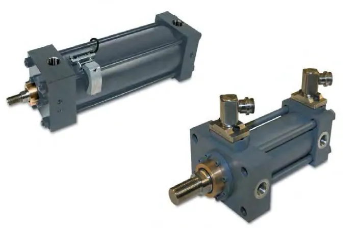
2.1.1 Actuator
An actuator is a type of motor which responsible for controlling or moving a system or mechanism. It is operated by a source of energy typically electric current, pneumatic pressure, or hydraulic pressure and convert that energy into motion. An actuator is the mechanism where a control system acts upon an environment. Control system can be simply fixed as mechanical or electronic system, a human, software-based such as printer driver or robot control system or any other input. Fluid power actuator receives fluid from pump which is usually driven by an electric motor. After the fluids has been pressure, flowing and directionally controlled, the actuator convert it energy into linear or rotary motion to do some useful work. Cylinders usually account for more than 85% of the actuators used in the fluid power system for work output. Of the approximately 15% of actuator that produce rotary output, more than 80% are hydraulic motor, while the rest are some forms of rotary actuators.
For a simple single acting cylinder, the cylinder is only forceed in one direction and need another force to return it such as an spring or external load. Fluid is not present on the low pressure side. Single acting cylinder often are weight returned and mounted vertically up. When a cylinder is mounted horizontally or vertically down, it must have some method of retracting it to the original position. Small single acting cylinder is mounted alongside the large ram work which rise and hold it in the up position with counterbalance valve. a bi-directional pump or a directional valve direct fluid to the pull or push cylinders to make it cycles. The other retraction method use is single acting cylinder which opposes the plate movement from the opposite side.
Figure 2.2: Examples of fluid power actuator (Alkyne, 2000)
The design for a double rod cylinder allow equal speed and force in both direction. It is useful in robotic mechanism which the rod will be clamped at both end and the body move instead.
2.1.2 Valves
Valves are important to control the flow rate, pressure and also the direction of the fluid. Hydraulic valve are made as a high standard of robustness and quality. We should remember that hydraulic are high pressure system and pneumatic system are low pressure system. Hydraulic valve are made from cheaper material (polymer and aluminium) and are cheap to manufacturer.
Control valves are imperative elements in both hydraulic and pneumatic systems which fluid flow is be manipulated or monitored. Selection of the proper valve involve a thorough knowledge of the process which for it will be used.
Selecting the proper valve is not only which type of valve will be use, but the size it must be to perform its design task and material of which it is made.
The basic valve is used for restrain or permit the flow of fluid and adjust the pressure in a system. The complete control valve is made of the valve itself, an actuator, and a valve control device. The actuator provides the required force to cause the closing part of the valve to move. Valve control device keeps the valves in the proper operating conditions. They will ensure appropriate position, interpret signals and manipulate responses.
For solenoid operated valves, a solenoid is a coil where an iron plung in it. When a current flow in the coil, the plung become magnetized and try to move out from the coil. The solenoid is use in relay which they operate the electric switch. They are also use in pneumatic and hydraulic valve to move the valve element.
Typically the valve is manually operated by push the plunger with a screw driver by turning the screw on other side. This is very useful for check if the valve was stuck. Modern solenoid valve are really pilot valve. A small electrically operated poppet valve is fitted at the end which lets air or oil through the end of the piston which pilot operates them.
2.1.3 Reservoir
Fluid power systems require fluid or oil to transmit energy. Usually pneumatic system uses the air we breathe as the source for their field. Receiver tank is similar to a hydraulic systems accumulator. Receiver tank stores energy for future use similar to a hydraulic accumulator. This is possible because the air is gas.
A receiver tank is a pressure vessel and constructed to pressure vessel standard. At the end of the work cycles the air is simply return to the atmosphere.
Hydraulic system on the other hand need a finite amount of fluid that must be store and reused always as the circuit work. Any part of hydraulic circuit is a storage tank
or reservoir. Reservoir implementation and design is very important. The efficiency of a hydraulic circuit will be greatly reduced by poor tank design. A hydraulic reservoir does much more than just provide a place to store fluid. A well-designed reservoir also dissipates heat which allow time for contamination to drop the fluid and allow air bubble to comes to the surface and dissipate. It may give a positive pressure to pump outlet and make a convenient mounting place for the pump and its valve or motor.
Figure 2.3: Example of hydraulic power steering reservoir (Alkyne, 2000)
The main reason the reservoir exist is the fluid to store. The accepted rule for sizing athe tank is the volume should be two times the pump flow in gpm. This is just a general rule. Some circuit may require more volume, where less fluid may be adequate for other circuits. The returned fluid theoretically will have two to three minutes in the tank before it can circulates again with this general rule. A baffle separate the return line from the pump outlet line which forced by the fluid to take the long path through the reservoir before return to the pump outlet.
This arrangement also mixes the fluid and provide more time to drop. Moreover, the fluid spend more time in contact with the outer wall of the reservoir to dissipate heat.
2.1.4 Pump
[image:24.595.206.420.207.398.2]Both hydraulic and pneumatic systems require a pump, even the compressed air is stored in tank before being transmitted. Both systems use valves to control the force and velocity of the actuators which are similar to each motive.
Figure 2.4: Examples of pneumatic pump (Alkyne, 2000)
A hydraulic pump is a mechanical device which convert mechanical power into hydraulic energy. It generate flow with enough power to overcome pressure which produce by the load. When a hydraulic pump operate it perform to function. The mechanical action create a vacuum at the pump inlet which allows atmospheric pressure to force the liquid from the reservoir into the inlet line to the pump. Second, its mechanical action delivers the liquid to the pump outlet and force it into the hydraulic systems. All pump may be classified either non positive displacement or positive displacement. Most pump used in hydraulic system are positive displacement. A non positive displacement pumps produce a continuous flow because it do not provide a positive internal seal with slippage.
The variable output considerably as pressure vary. Propeller and centrifugal pump are example of non positive displacement pump. If the input port of a non-positive