This is a repository copy of Machining of Carbon Fibre: Optical Surface Damage
Characterisation and Tool Wear Study.
White Rose Research Online URL for this paper:
http://eprints.whiterose.ac.uk/128998/
Version: Published Version
Article:
Duboust, N. orcid.org/0000-0001-7960-0196, Melis, D., Pinna, C.
orcid.org/0000-0002-9079-1381 et al. (4 more authors) (2016) Machining of Carbon Fibre:
Optical Surface Damage Characterisation and Tool Wear Study. Procedia CIRP, 45. pp.
71-74. ISSN 2212-8271
https://doi.org/10.1016/j.procir.2016.02.170
eprints@whiterose.ac.uk
https://eprints.whiterose.ac.uk/
Reuse
This article is distributed under the terms of the Creative Commons Attribution-NonCommercial-NoDerivs
(CC BY-NC-ND) licence. This licence only allows you to download this work and share it with others as long
as you credit the authors, but you can’t change the article in any way or use it commercially. More
information and the full terms of the licence here: https://creativecommons.org/licenses/
Takedown
If you consider content in White Rose Research Online to be in breach of UK law, please notify us by
Procedia CIRP 45 ( 2016 ) 71 – 74
2212-8271 © 2016 Published by Elsevier B.V. This is an open access article under the CC BY-NC-ND license (http://creativecommons.org/licenses/by-nc-nd/4.0/).
Peer-review under responsibility of the scientific committee of the 3rd CIRP Conference on Surface Integrity (CIRP CSI) doi: 10.1016/j.procir.2016.02.170
ScienceDirect
3rd CIRP Conference on Surface Integrity (CIRP CSI)
Machining of carbon fibre: optical surface damage characterisation and tool
wear study
N.Duboust
a*, D.Melis
b, C.Pinna
a, H.Ghadbeigi
a, A.Collis
c, S.Ayvar-Soberanis
b, K.Kerrigan
ba Department of Mechanical Engineering, University of Sheffield, UK
b AMRC with Boeing, Advanced Manufacturing Park, Wallis Way, Catcliffe, Rotherham, S60 5TZ c Rolls-Royce, 62 Buckingham Gate, London,UK
* Corresponding author. E-mail address: n.duboust@sheffield.ac.uk
Abstract
Better control of fibre composites machining requires reliable surface roughness and damage characterisation measurements. The performance and tool wear rate of three different state of the art CVD and PCD cutting tools manufactured for carbon fibre machining were compared in wet and dry conditions. Machined surfaces were characterised by areal surface roughness
parameters using a novel focus variation optical system. The tool wear and cutting forces were recorded up to 50 linear meters of machining or until tool failure. Results showed that wet machining conditions reduced tool failure; and that the CVD tool in wet conditions machined the greatest distance of 26m before reaching an average roughness limit of 3 m. The tool type was found to be the most significant parameter on the surface quality. The optical system was found to be a useful tool for measuring roughness of individual plies and characterising machining induced surface damage.
© 2016 The Authors. Published by Elsevier B.V.
Peer-review under responsibility of the scientific committee of the 3rd CIRP Conference on Surface Integrity (CIRP CSI)
Keywords: carbon fibre; surface analysis; surface roughness; composite machining; edge trimming; tool wear; PCD; CVD
1.Introduction
In machining of composite materials, reducing damage and reliable surface roughness characterization is necessary. The fibres in CFRP are highly abrasive and can lead to rapid tool wear. Also, surface defects including delamination, fibre pull-out, un-cut fibres and matrix burning can be a problematic. Studies have shown that standard cutting tools like; high speed steel, cemented carbide and existing nitrogen and carbon based coatings have insufficient wear resistance for composite machining [1,2]. It has also been shown that they produced a surface with poor quality and damage [3,4]. The superior wear resistance of polycrystalline diamond (PCD) and diamond coated tools has led to their increasing use in composite machining. Due to their high hardness these tools can maintain a sharp cutting edge and reduce surface defects.
Typically, roughness measurements made with a stylus have been used to identify machining damage, but previous
research shows that this is unreliable for composite surfaces [5,6]. The variation in roughness reading can be dependent upon measurement position; because the stylus path may pass over multiple fibre orientations, or deviate due to protruding fibres [6]. It has been shown that fibre orientation will affect the cutting mechanism and surface roughness [7,8,9]. The motivation for this work was therefore to research machining damage and tool wear rate using new diamond coated and PCD cutting tools. An optical focus variation system was used to characterise surface roughness according to ISO 4287. The surface roughness was analyzed using this new non-contact optical system to take areal parameters and it is believed this method has some advantages over tactile methods.
2.Experiment
In this research, machining experiments by edge trimming were conducted with three different milling tools. The effects
© 2016 Published by Elsevier B.V. This is an open access article under the CC BY-NC-ND license (http://creativecommons.org/licenses/by-nc-nd/4.0/).
72 N. Duboust et al. / Procedia CIRP 45 ( 2016 ) 71 – 74
2 Nicolas Duboust/ Procedia CIRP 00 (2016) 000–000
of tool wear, machining forces and surface quality under wet and dry machining conditions were compared. In the dry conditions air extraction was used to remove cut particles. In the wet machining, flood coolant and a filtration system was used- which can achieve 1 m particle filtration level. The tools were worn by machining until tool failure or a maximum of 54 linear meters. Fig. 1 shows the dynamometer used for cutting force measurement and the composite panel and vacuum fixture. The carbon fibre workpiece is 10mm thick made of an M21 epoxy resin and T700 fibre type.
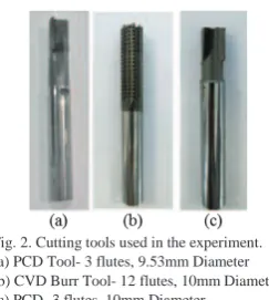
Two PCD and one diamond coated tool were compared- shown in Fig. 2. These will be referred to as tool (a), (b) and (c). Tool (b) is a solid carbide diamond coated tool, with nanocrystaline CVD coating. It is a burr style tool with a segmented helix and 12 flutes. Multiple cutting teeth are created when the primary helix is intersected. There are two cutting edges on each tooth, and a third edge which allows material removal. Tools (a) and (c) are both PCD with three flutes. The PCD Tool (a) has variable helix angle flutes with one negative one positive and one zero to minimise delamination. Tool (c) has 3 positive helix angle flutes. The cutting conditions and tool machining distance reached before catastrophic tool failure are shown in Table 1, and each test was repeated once. Cutting feeds and speeds were chosen
according to manufacturer’s recommended cutting parameters, and a similar feed per tooth was used across the three tools. In industry machining time needs to be optimised while maintaining surface quality. Therefore, a relatively high feed was chosen to challenge the capability of the milling tools.
Table 1. Machining parameters and meters Machined by tool before failure.
Optical microscope images were used in order to take tool edge wear measurements. These were performed by setting the tool in a reference position. The increase in tool edge wear was measured using edge recessions between a new and set point, where the initial wear was taken as zero for an unworn tool. These measurements were verified with edge radius
measurements using the Alicona optical system which can take 3D scans of the cutting edge. The edge radius measurements were found to show a similar trend with machining distance to the edge recession measurements. It was chosen to use the results from optical microscope because the edge radius of the complex CVD burr tool geometry could not be reliably measured using the optical system. The cutting forces were measured by Kistler dynamometer in the feed and radial directions. Fy and Fx are in the direction shown in Fig.
1(a), with Fy in the feed direction and Fx perpendicular to the
feed. For the force measurements a sampling frequency of 20,000 Hz was used to convert analogue to digital for the charge signal taken from dynamometer. The cutting forces were averaged across the cutting period removing a section at the beginning and end of cut. Surface roughness measurements were made using an optical system manufactured by Alicona [10]. This instrument can generate 3D surface images and works by focus variation. Roughness measurements were taken in three positions on the sample with a cut-off wavelength of 800 m; a vertical resolution of 100nm and lateral resolution of 2µm. A sample 2mm wide by 10mm high was used. Roughness parameters Sa, and
Skewness and Kurtosis were taken. The laminate has a quasi-isotropic stacking sequence with fibre orientations of 0, 45, 90 and 135 degrees. In order to see the effects of fibre orientation on surface damage, the average roughness was measured across the individual fibre orientations. The stacking sequence of each ply of the layup was known; therefore each fibre orientation could be measured by using the top and centre plies as a reference. The optical system allows individual laminate layers to be viewed and then selected for roughness measurement as shown in Fig. 3.
3. Results
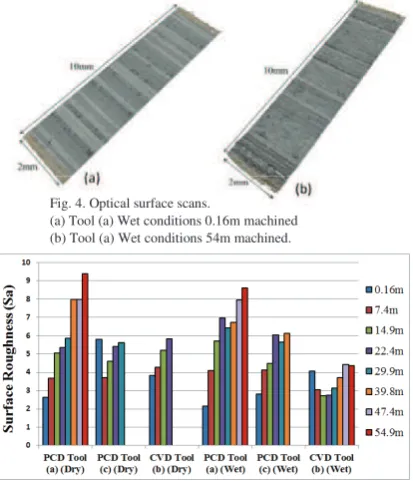
Optical surface scans in Fig. 4. show the machined surface for the PCD tool (Fig. 2(a)), in wet conditions. Fig. 4(a) shows the machined surface profile with a new tool, while Fig. 4(b) shows the surface after the tool has machined 54m of material. It can be seen that there is a variation in surface damage and structure across the different layers of the laminate which have different fibre orientations, and that the surface appears rougher in Fig. 4(b) with more damage on the top and bottom plies. Fig. 5. shows the average surface roughness (Sa) as a
function of meters machined in wet and dry conditions. It is seen that there is an increase in roughness as tool wear increases with meters machined, across each of the tool conditions. The PCD tool (a) reached the maximum of 54m of machining in both the wet and dry conditions. While, the CVD tool (b) and PCD tool (c) both failed catastrophically in the
Feed Rate, Cutting Speed and Feed per
Tooth
Meters Machined
Sa at 30m Machined
Distance machined to reach minimum
Sa of 3 m Tool (a) PCD
(DRY)
1.2m/min, 10000 RPM,
feed/tooth- 0.04mm 54m 5.99 7.4m
Tool (b) CVD (DRY)
6.1m/min, 12,739 RPM, feed/tooth- 0.04mm
22m (Failure)
22m
(Failure) 0.16m
Tool (c) PCD (DRY)
1.5m/min, 10,000 RPM, feed/tooth- 0.05mm
30m
(Failure) 5.33 0.16m
Tool (a) PCD (WET)
1.2m/min, 10000 RPM,
feed/tooth- 0.04mm 54m 6.41 7.4m
Tool (b) CVD (WET)
6.1m/min, 12,739 RPM,
feed/tooth- 0.04mm 54m 3.13 26.2m
Tool (c) PCD (WET)
1.5m/min, 10,000 RPM,
feed/tooth- 0.05mm 40m 5.64 7.4m
Fig. 1. (a) Dyno and machining force direction
[image:3.595.349.471.66.202.2](b) Wear panels and vacuum fixture- edge trimming Fig 1 (a) Dyno and machining force direction
Fig. 2. Cutting tools used in the experiment. (a) PCD Tool- 3 flutes, 9.53mm Diameter (b) CVD Burr Tool- 12 flutes, 10mm Diameter (c) PCD- 3 flutes, 10mm Diameter
[image:3.595.76.277.212.325.2]dry conditions before reaching 54m. The wet conditions were therefore found to extend tool life in this situation, which could be attributed to a reduction in friction and cooling of the tool. Tool failure was caused by a buildup of machining forces and friction due to tool wear. The lowest overall roughness was found in the diamond coated tool (b) in wet conditions.
The average Sa roughness measured across the different
fibre orientations is shown in Fig. 6. These were taken across the 3 tool types from the cuts made at 30m and 40m of machining. The fibre orientation definition is described in reference [9]. It can be seen that the 135 degree orientation had a significantly higher roughness than the other orientations. Therefore the surface quality and roughness on the machined surface is dominated by the 135 orientation. Roughness measurements should therefore include all fibre orientations in order to give a representative damage of the whole surface. It was found that there is an advantage to using areal parameters on a multi-directional laminate due to the variation in surface structure or damage at different fibre orientations. For that reason the Sa areal roughness parameters used in this research are advantageous because they are more robust to changes in measurement position than Ra, and therefore will more reliably characterise damage.
3.2 Tool Wear Measurements
The edge recession vs machining distance compared across the tools is shown in Fig. 7. Across all of the tools an initially fast wearing in period was seen. In the PCD tools this was by edge chipping from the abrasive carbon fibres. It was seen that as the wear in the tool develops and the cutting edge radius increases the wear rate becomes more gradual. There will be a corresponding negative effect on the cutting forces and surface quality as cutting edge radius increases. Therefore, it is important to use a tool which will have a low wear rate and can maintain a sharp cutting edge. The wear rate in the diamond coated tool (b) was lower than in the PCD tools. Tool wear in the diamond coated burr-style tool was found to be different than the PCD tools. Rather than gradual edge rounding of the cutting edge there was delamination causing damage to single cutting teeth. Delamination happened when chunks of diamond grain break off or fracture. For the PCD tool (c) the wear rate was higher in Dry conditions. As shown
previously in Fig. 5. the surface roughness was found to be
significantly lower while machining with the diamond coated tool in wet conditions, and followed a different trend than for the PCD tools; first decreasing with an initial wear in period of the tool. The initial decrease in the roughness of machined surface may be due to smoothing of the surface grains of the diamond coating on the cutting tool, which is then followed by an increase in roughness as the number of damaged teeth rises.
3.3 Cutting forces
It was found that Fy had the strongest correlation with tool wear and increased with machining distance- Fig. 8. The
highest forces Fy were seen in the CVD tool (b) which is
because of the high feed rate used. Fy was found to be generally similar between the wet and dry conditions for the
PCD tools. However, Fy was initially slightly higher in the
[image:4.595.305.487.70.181.2] [image:4.595.94.273.134.277.2]wet than dry conditions which may be due to cooling of the Fig. 6. Average roughness (Sa) vs fibre orientation.
[image:4.595.75.282.462.703.2]Fig. 3. Optical Surface Scans and roughness measurement of individual ply fibre orientations.
Fig. 7. Tool edge recession vs meters machined for dry and wet conditions.
Fig. 5. Sa Surface roughness versus meters machined.
Fig. 4. Optical surface scans.
[image:4.595.312.516.480.590.2]74 N. Duboust et al. / Procedia CIRP 45 ( 2016 ) 71 – 74 workpiece. In the dry conditions there are higher workpiece
temperatures and a softening of the matrix which may cause the fibres to be held together less strongly. The CVD tool appeared to perform better in the wet conditions where after the initial 15m of machining the machining forces were significantly lower.
3.4 Skewness and Kurtosis
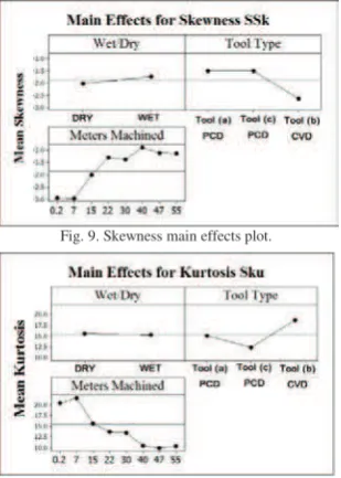
The skewness and kurtosis were measured across the samples using the optical system to give more information about surface damage. The Skewness is a measure of the symmetry of the height distribution, and gives information about the amount of hills or valleys on the surface. The Kurtosis explains the peak and valley sharpness and highlights whether the surface profile distribution is either steep or rounded. In the main effects plot (Fig. 9.), it was found that the skewness increases with machining distance due to tool wear. A positive skewness defines a surface which has more valleys. This means that as the tool wear increased the amount of surface pitting increased. It was found that the mean effect of the Kurtosis in Fig. 10 was that it decreased with an increase in tool wear or distance machined- this characterises a surface with rounded peaks rather than sharp ones. This can be explained by the tendency for large pieces of material to be removed as the machining damage increased and the surface roughness is higher. When the machining damage is less the surface is smoother and is dominated by protruding or un-cut fibres which have a sharp profile.
The CVD tool (b) in the wet conditions was found to have the lowest Skewness and we hypothesise that this correlated to lower machining damage.
4. Conclusions
Three different cutting tools were compared under wet and dry cutting conditions for carbon fibre edge trimming. It was found that the surface roughness increased with machining distance generally following a steady trend, while the tool wear was found to initially have a rapid wearing in period. Wet machining conditions were also found to increase tool life and reduce catastrophic tool failure. The CVD burr-style tool in wet conditions machined a total of 26m before reaching a roughness limit of 3 m. The optical focus variation system was found to be a useful tool for characterising surface roughness of a machined non-homogeneous multi-directional composite, along with the use of areal roughness measurements. It can be concluded that diamond coated tool with multiple cutting teeth will be able to produce a surface of good quality, even at a high production or feed rate. The literature showed that PCD and diamond coated tools will provide the best current solution for machining of composite materials; but further analysis is needed to compare the overall costs of wet vs dry machining in order to find the best solution for this application.
Acknowledgements
Our thanks go to the Advanced Manufacturing Research Centre (AMRC), of the University of Sheffield. This work was co-funded through the EPSRC Industrial Doctorate Centre in Machining Science (EP/I01800X/1) and by Rolls-Royce whom the authors would like to thank.
""
References
[1] M. Henerichs, C. Dold, R. Voss, and K. Wegener, “Performance of Lasered PCD-and CVD-Diamond Cutting Inserts for Machining Carbon Fiber Reinforced Plastics (CFRP),” pp. 1–8, 2014.
[2] R. Teti, “Machining of Composite Materials,” CIRP Ann. - Manuf. Technol., vol. 51, no. 2, pp. 611–634, Jan. 2002.
[3] J. Zhang, X. Wang, B. Shen, and F. Sun, “Effect of boron and silicon doping on improving the cutting performance of CVD diamond coated cutting tools in machining CFRP,” Int . J. Refract. Met. Hard Mater., vol. 41, pp. 285–292, 2013.
[4] J. Zhang and B. Shen, “Fabrication and Drilling Tests of Chemical Vapor Deposition Diamond Coated Drills in Machining Carbon Fiber Reinforced Plastics,” J. Shanghai Jiaotong Univ., vol. 18, no. 4, pp. 394–400, 2013. [5] M. Ramulu, C. W. Wern, and J. L. Garbini, “Effect of fibre direction on surface roughness measurements of machined graphite/epoxy composite,”
Compos. Manuf., vol. 4, no. 1, pp. 39–51, Jan. 1993.
[6] A. I. Azmi, R. J. T. Lin, and D. Bhattacharyya, “Experimental Study of Machinability of GFRP Composites by End Milling,” Mater. Manuf. Process., vol. 27, no. 10, pp. 1045–1050, Oct. 2012.
[7] D. Wang, M. Ramulu, and D. Arola, “Orthogonal cutting mechanisms of graphite/epoxy composite. Part I: Unidirectional laminate,” Int. J. Mach. Tools Manuf., vol. 35, no. 12, pp. 1623–1628, 1995.
[8] M. H. El-Hofy, S. L. Soo, D. K. Aspinwall, W. M. Sim, D. Pearson, and P. Harden, “Factors Affecting Workpiece Surface Integrity in Slotting of CFRP,”
Procedia Eng., vol. 19, pp. 94–99, Jan. 2011.
[9] J. Sheikh-Ahmad, Machining of Polymer Composites. Boston, MA: Springer US, 2009.
[10] “Alicona.” [Online]. Available:
http://www.alicona.co.uk/home/products/infinitefocus-standard/focus-variation.html. [Accessed: 19-Nov-2013].
[image:5.595.74.278.134.271.2] [image:5.595.93.248.503.720.2]