ii
UNIVERSITI TEKNIKAL MALAYSIA MELAKA
STUDY ON THE EFFECT OF VARIATION IN ECU
PARAMETERS TO THE ENGINE PERFORMANCE OF A
TURBO ENGINE
This report submitted in accordance with requirement of the Universiti Teknikal Malaysia Melaka (UTeM) for the Bachelor Degree of Mechanical Engineering
Technology (Automotive Technology) (Hons.)
by
DIVENTHIRAN A/L RAVINDRAN B0713100784
941125-01-6589
iii
DECLARATION
I hereby, declared this report entitled “Study on The Effect of Variation in ECU Parameters to the Engine Performance of a Turbo Engine” is the results of my own research except as cited in references.
Signature : ………..
Author’s Name : Diventhiran a/l Ravindran
1
APPROVAL
This report is submitted to the Faculty of Engineering Technology of UTeM as a partial fulfilment of the requirements for the degree of Bachelor Degree of Mechanical Engineering Technology (Automotive Technology) with Honours. The member of the supervisory is as follow:
……….
2
ABSTRACT
3
ABSTRAK
4
DEDICATIONS
5
ACKNOWLEDGMENTS
6
TABLE OF CONTENT
DECLARATION...iii
APPROVAL...iv
ABSTRACT...v
ABSTRAK...vi
DEDICATIONS...vii
ACKNOWLEDGMENTS...viii
TABLE OF CONTENT...ix
LIST OF TABLES...xii
LIST OF FIGURES...xiii
LIST OF ABBREVIATION, SYMBOLS AND NOMENCLATURE...xiv
CHAPTER 1 1.0 BACKGROUND...1
1.1 PROBLEM STATEMENT………...2
1.2 OBJECTIVES...3
1.3 SCOPE OF RESEARCH... ...4
CHAPTER 2 2.0 INTRODUCTION...5
2.1 ECU………...5
2.2 PROGRAMMABLE ECU……...6
2.3 VARIATION IN ECU PARAMETERS...7
2.3.1 PROGRAMMING MANIFOLD ABSOLUTE POSITION……7
2.3.2 PROGRAMMING OXYGEN SENSOR………...8
7
2.4 SENSORS……….10
2.4.1 AIR FLOW SENSOR………..10
2.4.2 MASS AIR FLOW SENSOR………..11
2.4.3 THROTTLE POSITION SENSOR……….11
2.4.4 CRANKSHAFT SENSOR………..11
2.5 ACTUATORS………..12
2.5.1 ELECTRONIC THROTTLE VALVE………12
2.5.2 ELECTRIC WASTEGATE……….13
2.5.3 WATER PUMP………...14
2.6 ENGINE PERFORMANCE……….15
2.7 DYNAMOMETER………...16
2.7.1 ENGINE DYNAMOMETER………..16
2.7.2 CHASSIS DYNAMOMETER………17
2.7.3 ADVANTAGES AND DISADVANTAGES……….18
CHAPTER 3 3.0 INTRODUCTION...19
3.1 SELECTION OF THE ENGINE………....20
3.2 AREA OF TEST………...20
3.3 PERFORMANCE TESTING…...21
3.3.1 CHASSIS DYNAMOMETER………...21
3.4 ECU TUNING...22
3.5 DATA COLLECTION...24
3.6 EXPERIMENTAL PROCEDURE...24
CHAPTER 4 4.0 INTRODUCTION………...25
8
4.2 FIRST RUN WITH STANDARD ECU SETTING………...26
4.3 SECOND RUN WITH FIRST ADJUSTED ECU SETTING………29
4.4 THIRD RUN WITH SECOND ADJUSTED ECU SETTING……...33
4.5 COMPARISON BETWEEN STANDARD ECU SETTING AND ADJUSTED ECU SETTING………..37
4.5.1 COMPARISON OF TORQUE………..38
4.5.2 COMPARISON OF HORSEPOWER………...40
CHAPTER 5 5.0 INTRODUCTION………...43
5.1 PERFORMANCE………43
5.2 RECOMMENDATION………...45
9
LIST OF TABLES
Table 1.3: Engine Specification………...3
Table 2.7.3.1 Engine Dynamometer………...18
Table 2.7.3.2 Chassis Dynamometer………..18
Table 3.1 Specifications of K3-VET………..20
Table 4.2.1: Details of Vehicle and Dynamometer Details………26
Table 4.2.2: Table of Torque and RPM for Standard ECU Setting………26
Table 4.2.3: Table of Horsepower and RPM for Standard ECU Setting………28
Table 4.3.1: Details of Vehicle and Dynamometer……….29
Table 4.3.2: Table of Torque and RPM for First Adjusted ECU Setting…………...30
Table 4.3.3: Table of Horsepower and RPM for First Adjusted ECU Setting……...31
Table 4.4.1: Details of Vehicle and Dynamometer……….33
Table 4.4.2: Table of Torque and RPM for Second Adjusted Setting………34
Table 4.4.3: Table of Horsepower vs RPM for Second Adjusted ECU Setting…….36
Table 4.5.1.1: Table of Torque vs RPM for Run 1, 2, 3……….38
Table 4.5.1.2: Table of Comparison of Torque………..39
Table 4.5.2.1: Table of Horsepower and RPM for Run 1, 2, 3………..40
Table 4.5.2.2: Table of Comparison of Horsepower………..41
Table 5.1.1: Comparison of Horsepower………44
10
LIST OF FIGURES
Figure 2.1 Bosch ECU of BMW X5 4.4i………..6
Figure 2.2 Programmable ECU……….7
Figure 2.4.4 Crankshaft Sensor………...12
Figure 2.5.1 Electronic Throttle Valve………...13
Figure 2.5.2 Wastegate Regulator Valve………14
Figure 2.5.3 Water Pump………15
Figure 2.7.1 Engine Dynamometer……….16
Figure 2.7.2 Chassis Dynamometer………17
Figure 3.4.1Haltech Pro Plug-In Series………..22
Figure 3.4.2: Air Flow Adjustment Mapping for Run 2……….23
Figure 3.4.3 Air Flow Adjustment Mapping for Run 3………..23
Figure 4.2.1: Graph of Torque vs RPM for Standard ECU setting………27
Figure 4.2.2: Graph of Horsepower vs RPM for Standard ECU Setting…………..28
Figure 4.3.1: Graph of Torque vs RPM for First Adjusted ECU Setting…………..30
Figure 4.3.2: Graph of Horsepower and RPM for First Adjusted ECU Setting……32
Figure 4.4.1: Graph of Torque vs RPM for Second Adjusted ECU Setting………..35
Figure 4.4.2: Graph of Horsepower vs RPM for Second Adjusted ECU Setting….36 Figure 4.5.1.1: Graph of Torque vs RPM………...39
11
LIST OF ABBREVIATIONS, SYMBOLS AND
NOMENCLATURE
FTK - Fakulti Teknologi Kejuruteraan
L - Litre
UTeM - Universiti Teknikal Malaysia Melaka ECU - Electronic Control Unit
1
CHAPTER 1
INTRODUCTION
1.0 Background
Cars are very important transportation for everybody. Modern cars nowadays are very much electronic comparing to old times where cars use the old mechanical system such as carburettor and ignition distributor. In modern car the tasks of ignition distributor and carburettor is performed by electronic ignition system and electronic injection system. What does this electronic system means? The electronic system is controlled by the brain of the car which is the Electronic Control Unit (ECU). ECU is the brain of the car which associate with responding sensors, collect the data from the sensors, calculate the desired output and give command to the respective actuators to perform some task according to the driver’s intention. There is no escape from the ECU in the modern car.
But the tuning of the engine is initially done by the manufacturers with standard setting of the ECU. We can tune the ECU in order to get the best efficiency from the car engine. Efficiency of the engine is the main concern for the driver about the ECU properties. In order to get the best efficiency and maximum performance from the car engine, we have to tune the ECU into best configuration. This can be acquired by changing some of the ECU properties. Such as the ignition timing, fuel injection timing, or changing the intake air temperature.
2
cannot make further adjustments to the engine parameters in order to extract the best engine torque and maximum efficiency from the engine. This project involved the development of a research ECU (RECU) using reconfigurable programme control system for a four-stroke port fuel injected gasoline engine (B.Prem Anand, C.G.Saravanan.).
In this project, there are some sensors which play important roles in sensing, collecting and sending the required data or information to the ECU. These sensors are such as intake air temperature sensor, exhaust temperature sensor, throttle position sensor, oxygen sensor, and crankshaft sensor. For example, according to the signal from throttle position sensor and crankshaft position sensor ECU actuates injector to inject fuel quantity in terms of injector pulse width and actuates spark plug to fire (S. J. Adsul, P. A. Mane and S. S. Mulay.2013).
1.1 Problem Statement
In automotive industry, the main concern of the manufacturers is to enhance the engine performance. In order to achieve this, the engine of the vehicle should have a good efficiency. To produce an engine with the best efficiency the manufacturers invent the computer system based engine which is led by the brain of the engine, ECU. With ECU the manufacturers configure the best performance for the customers. But, the ECU can further tuned in order to get the best and maximum performance with almost full efficiency from the engine. We have to decide which parameter is best to be tuned to get maximum performance from the engine according to the driving conditions.
3
1. To analyse the horsepower of the turbo engine for standard ECU setting and adjusted ECU setting.
2. To analyse the torque of the turbo engine based for standard ECU setting and adjusted ECU setting.
3. To get data from the chassis dynamometer and for standard ECU settings and adjusted ECU settings.
1.3 Scope of Research
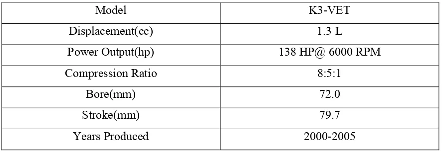
[image:16.595.65.511.552.705.2]This project is mainly about a turbocharged engine. The scope is for petrol engine only. This project is mainly about the variation on throttle position. This research analyse about the engine performance of a turbo engine. One of the YRV engines which is K3-VET engine is used for this project. K3-VET engine uses double overhead camshaft and indirect injection system. K3-VET is turbocharged and uses petrol as fuel for its internal combustion. These are the specification of the engine:
Table 1.3: Engine Specification
Model K3-VET
Displacement(cc) 1.3 L
Power Output(hp) 138 HP@ 6000 RPM
Compression Ratio 8:5:1
Bore(mm) 72.0
Stroke(mm) 79.7
4
offers until 138 HP. Because it has electronic ignition system it uses the ECU as the brain of the engine.
5
CHAPTER 2
LITERATURE REVIEW
2.0 Introduction
This part will review about the previous studies and researches about this project. Moreover, this part will discuss about the information needed to carry out this project. It also will explain about the methods used to carry out this experiment.
2.1 ECU
6
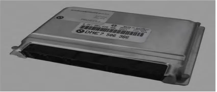
[image:19.595.108.534.196.378.2]PCB, typically in EPROMs or flash memory so the CPU can be re-programmed by uploading updated code or replacing chips. This is also referred to as an (electronic) Engine Management System (EMS).
Figure 2.1 Bosch ECU of BMW X5 4.4i
2.2 Programmable ECU
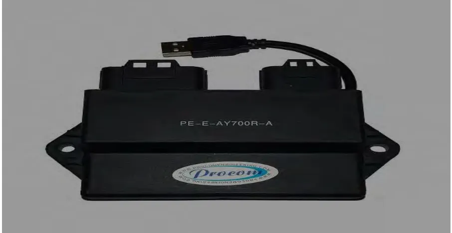
But the tuning of the engine is initially done by the manufacturers with standard setting of the ECU. We can tune the ECU in order to get the best efficiency from the car engine. Efficiency of the engine is the main concern for the driver about the ECU properties. In order to get the best efficiency and maximum performance from the car engine, we have to tune the ECU into best configuration. This can be acquired by changing some of the ECU properties. A special category of ECU is those which are programmable. These units do not have a fixed behaviour and can be reprogrammed by the user.
7
Figure 2.2 Programmable ECU
2.3 Variation in ECU Parameters
There are many parameters of ECU can be tuned to enhance the engine performance. These different parameters can give you a different result of engine performance. There are different methods to tune the engine parameters because it involves a lot of different sensors and actuators working on the parameter.
2.3.1 Programming Manifold Absolute Position
8
and intake manifold pressure changes the voltage signal. The MAP sensor converts the intake manifold pressure into a voltage signal.
Vo = 0.03P + 0.6, (2) when P = 120 kPa, Vo = (0.03×120) + 0.6,
Vm = 4.2 volts, where:
Vo – Output voltage from MAP sensor, Volts, P – Atmospheric pressure, kPa,
Vm – Maximum output voltage, Volts.
2.3.2 Programming Oxygen Sensor
According to B. Prem Anand, C.G. Saravanan (2012), the RECU uses an oxygen sensor to ensure the air fuel ratio is correct for the catalytic converter. Based on the oxygen sensor signal, the RECU is programmed to adjust the amount of fuel injected into the intake air stream. The oxygen sensor generates a voltage signal based on the amount of oxygen in the exhaust compared to the atmospheric oxygen. When exhaust oxygen content is high, oxygen sensor voltage output is low. When exhaust oxygen content is low, oxygen sensor voltage output is high. The greater the difference in oxygen content between the exhaust stream and atmosphere, the higher the voltage signal. From the oxygen content, the RECU could determine if the air fuel ratio is rich or lean by giving output signals. A rich mixture consumes nearly all the oxygen, so the voltage signal is high, in the range of 0.6-1.0 volts.
9
(TPS) is mounted on the throttle body and converts the throttle valve angle into an electrical signal. As the throttle opens, the signal voltage increases. At idle, voltage is approximately 0.6 volts on the signal wire. From this voltage, the ECU knows the throttle plate is closed. At wide-open throttle, signal voltage is approximately 3.6 volts. Inside the TPS a resistor and a wiper arm is available and arm is always contacting the resistor. At the point of contact, the available voltage is the signal voltage and this indicates throttle valve position. At idle, the resistance between the power to ground terminal is high, therefore, the available voltage is approximately 0.6. As the contact arm moves closer, the power voltage resistance decreases and the voltage signal increases. Using VI, programme was developed while simulating functions of TPS by observing idle and wide open throttle as minimum and maximum conditions. When the throttle is operated at an intermediate value other than the calibrated one, the TPS - VI programme would give proportional output as it was programmed to follow the linear characteristics of the TPS.
Eo = kp �, when � = 90�, Em = 3.6 Volts,
where:
Eo – Output voltage, Volts,
10
Sensors function to sense any difference in its environment and collect the data .The data collected will be sent to the ECU to perform some specific calculation. It is a type of transducer.
2.4.1 Air Flow Sensor
11
performance engines, sensors based on a thermal heat-loss principle, including a hot-wire element (plus a companion compensating hot-wire element), are mounted in a bypass channel of the air intake to measure mass air flow into an engine. This type of sensor measures true mass provided there’s no pulsating reversal of air flow. Under certain operating conditions, pulsating reversal of air flow does occur; in which case, another configuration of the thermal flow sensor is used. This type utilizes a heat source and dual upstream and downstream thermal flow-detection elements (William J. Fleming, 2001).
2.4.3 Throttle Position Sensor
The Throttle position sensor (TPS) is mounted on the throttle body and converts the throttle valve angle into an electrical signal. As the throttle opens, the signal voltage increases (B. Prem Anand, C.G. Saravanan). The sensor is usually located on the butterfly spindle/shaft so that it can directly monitor the position of the throttle. More advanced forms of the sensor are also used, for example an extra closed throttle position sensor (CTPS) may be employed to indicate that the throttle is completely closed. Some engine control units (ECUs) also control the throttle position electronic throttle control (ETC) or "drive by wire" systems and if that is done the position sensor is used in a feedback loop to enable that control (McKay, D., Nichols, G., and Schreurs, B).
2.4.4 Crankshaft Sensor