Performance of
fi
xed-parameter control algorithms on high-rise
structures equipped with semi-active tuned mass dampers
Demetris Demetriou, Nikolaos Nikitas* and Konstantinos Daniel Tsavdaridis
School of Civil Engineering, University of Leeds, Leeds, UKSUMMARY
The present study investigates the performance offixed parameter control algorithms on wind-excited high-rise structures equipped with semi-active tuned mass dampers of variable damping. It has been demonstrated that the algorithms that increase significantly the performance of the controlled structure do so at the ex-pense of damper strokes. When the maximum damper strokes are capped to progressively lower limits, the efficacy of different algorithms, measured through a number of performance objectives, drastically alters totally changing the performance ranking of them and pointing out the need for an extensive study of the interplay between loading, control algorithm and allowable stroke within the design of semi-active tuned mass dampers devices. 2015 The Authors.The Structural Design of Tall and Special Buildingspublished by John Wiley & Sons Ltd.
Received 19 July 2015; Accepted 13 September 2015
KEY WORDS: vibration mitigation; control algorithms; wind engineering; high-rise buildings
1. INTRODUCTION
Since the introduction of the tuned mass damper (TMD) to the engineering community by Frahm in 1911 (Frahm, 1911), a large number of studies have been published validating the applicability and effectiveness of TMDs on high-rise and slender structures (Kawaguchiet al., 1992; Xu et al., 1992; Caoet al., 1997; Sadek and Mohraz, 1998; Liuet al., 2008; Casciati and Giuliano, 2009). In an attempt to improve further the effectiveness andflexibility of the device, researchers across the world have suc-cessfully altered the original design by incorporating sophisticated passive, semi-active and active el-ements. While the approach of upgrading the performance of the TMD using enhanced and innovative passive elements is reasonable from a technological, practical and economical perspective (Pinkaew and Fujino, 2001; Marian and Giaralis, 2014), this might not be always the case for semi-active and active control of structures because of the costs associated with the requirement of expensive actuators and specialized control components (such as electrorheological and magnetorheological dampers), which can be considered prohibitive for use on structural applications (Casciatiet al., 2012). Due to such limitations, over the years, an attempt has been made to improve the performance of actively and semi-actively controlled systems via the relatively easier design and selection of appropriate con-trol algorithms, suitable for implementation in full-scale civil structures.
In the literature, most of the algorithms adopted for use on semi-active tuned mass dampers (STMD)-equipped structures are based onfinding optimal control forces through the minimization of some cost function or performance index such as in the case of the linear quadratic regulator (LQR) and linear quadratic Gaussian (H2/LQG) control. Hrovatet al. (1983) were thefirst to suggest the use of variable damping dynamic absorbers on civil structures. They proposed an optimal control method for reducing the wind-induced vibration of a model two degrees of freedom (DOF) structure, demonstrating the superiority of the proposed system over a relevant traditional passive. Later, on a
*Correspondence to: Nikolaos Nikitas, School of Civil Engineering, University of Leeds, Leeds, UK. E-mail: [email protected]
similar study, Pinkaew and Fujino (2001) demonstrated the gains of the LQR-controlled STMD vari-able damping device on reducing the response of structures under harmonic excitations. They reported substantial improvements on the steady-state response of the structure around the tuning frequency, but only minor gains for the transient component of the vibration. Over the same years,‘another class of optimal control laws’, the so-called bang-bang (BANG) control method has been investigated. Wu and Soong (1996) and Jansen and Dyke (2000) investigated the performance of optimal and suboptimal BANG controllers on semi-actively controlled structures, comparing their effectiveness against other algorithms on the benchmark of earthquake-excited structures. Later, Kooet al. (2004) developed a semi-active control algorithm, termed‘groundhook control’for use on STMD variable damping de-vices. This algorithm was developed as an extension to the ‘skyhook control’algorithm proposed by Karnopp and Crosby (1974) for use on vehicle suspension systems. Theflexibility of the former lies on its simplicity of implementation, its computational efficacy and its demand for only two sensors in order to achieve the calculation of control actions. Validating the effectiveness of the groundhook con-trol scheme, Kanget al. (2011) examined the performance of different semi-active device confi gura-tions on wind excited tall structures, demonstrating that (displacement-based) groundhook-controlled STMD devices can substantially reduce the response of the structure when compared with passive TMD solutions. These authors also observed that using an optimally tuned displacement-based groundhook (DBG) controller, the predefined stroke limitations could not be satisfied; thus, an addi-tional passive damper was required for satisfying the stroke limitations. Most recently, Demetriou
et al. (2014) demonstrated that proportional-integral-derivative (PID) controllers can also be tailored for use on variable damping STMD-equipped structures subjected to earthquake excitations and outlined the benefits from the use of such a control strategy.
Even though all the quoted studies inarguably drew conclusions on the enhanced performance of the STMD-equipped system over its conventional passive analogue, it is evident that the once small and meaningless damper strokes (i.e. not being translated to practical applicable values) arising either due to the nature of the external perturbations (harmonic, white noise or short earthquake) and the system’s geometric and dynamic properties (low-rise and high-frequency structures) cannot be overlooked when it comes to high-rise structures subjected to long-term wind actions. For these reasons, no truly conclu-sive argument can be made regarding the relative performance of (a) STMD over TMD equipped struc-tures and (b) the gains arising from different algorithms on high-rise strucstruc-tures equipped with STMD variable damping devices; particularly when the main performance-limiting factor is the stroke of the damper; this evidently needs to be taken into account for reaching any performance verdict.
Naturally in this study, the effectiveness of a variable damping STMD device on alleviating dy-namic response of a benchmark high-rise structure is investigated, and the relative performance offive of the most popularfixed parameter feedback algorithms, namely the groundhook (DBG and velocity-based groundhook (VBG)), clipped optimal, BANG and PID controls, is reassessed. The dynamic in-put takes the form of a wind buffeting-type load, always of interest to high-rise buildings. Discussions on both quantitative and qualitative gains arising from the use of each control algorithm are sought, while at the same time, the fairness of all comparisons is explicitly preserved. As a novel feature, the possibility of switching to an appropriate algorithm for improving performance at the expense of low damper strokes is exploited in an attempt to avoid performance deterioration and cost due to the addition of an auxiliary damper when limited strokes are imposed.
2. MODELLING THE SEMI-ACTIVE TUNED MASS DAMPERS CONTROLLED SYSTEM
The dynamic behaviour of a generic, linear, controlled building structure modelled as a swayn-DOF lumped mass system when subjected to an arbitrary disturbance is fully captured by its matrix equation of motion as follows:
M€x tð Þ þCx t_ð Þ þKx tð Þ ¼Bu tð Þ þDd tð Þ; (1)
calculated using an appropriate control algorithm; and B and D are the n× 1 influence matrices assigning the control and external force contributions, respectively, to the individual DOFs. For each DOF inx(t) being the displacement of theith(i= 1,..,n) mass,Mtrivially becomes diagonal, while for the specific viscous damping considered, the damping matrixCis assumed to have a form identical to the symmetric stiffness matrix K (i.e. classical damping approach). Without loss of generality, the system considered is equipped with a mass damper system attached to its (n1)thDOF, with the de-vices’motion variable constituting thenthDOF. Adopting a state–space formulation, Eq. (1) becomes the following:
_
z tð Þ ¼Az tð Þ þFu tð Þ þEd tð Þ; (2)
wherez t_ð Þrepresents thefirst-order time-change of the statesz tð Þ ¼ ½x tð Þx t_ð ÞTof the system;Ais the system block matrix containing the system’s mass, damping and stiffness properties;Fis the control force locator block matrix; andEis the external perturbation locator block matrix, such that
A¼ 0 I
M1K M1C
;F¼ 0 M1B
;E¼ 0 M1D
; (3)
withIbeing the identity matrix of appropriate dimensions (i.e.n×n).
Unlike a conventional passive TMD equipped system that produces an unregulated control force as a result of the relative motion ðx_rð Þt ;xrð Þt Þof its mass against its supports (i.e. between thenthand
(n1)thDOFs) such that
u tð Þ ¼kpxrð Þ þt cpx_rð Þt ; (4)
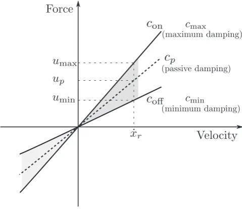
wherecpandkpare the passive damping and stiffness coefficients of the TMD; an STMD can be mod-ulated damping-wise between two values, referred to as passive maximum (cmax) and passive
mini-mum (cmin) as depicted in Figure 1. By employing a suitable control algorithm, the calculation of
[image:3.595.176.416.489.696.2]the appropriate maximum and minimum damping coefficients either directly or through the calculation
of a desired active force ua(t), one allows for enhanced overall energy dissipation capacity for the damper and improved performance of the vibration control system.
For the cases where a purely active algorithm such as the LQR or the PID is used for the calculation ofcmaxandcmin, the desired active forceua(t) needs to be calculated and tailored to an equivalent semi-active force, which can be physically realizable by the device. To this respect, because a semi-semi-active device can, by definition, only consume energy, functioning criteria need to be applied on the active control force. Namely, the semi-active forceusa(t) is calculated by the following:
usað Þ ¼t uað Þt
1sgn½uað Þt x_rð Þt
2
; (5)
sgn½uað Þt x_rð Þt ¼ sgnð Þ ¼qa
1
1
(
for
for
qa
qa
≤0
>0
: (6)
From this, the relevant power‘dissipation’of the semi-active deviceqsacan be calculated by
qsa¼usað Þt x_rð Þt <0; (7)
where the negative sign is only indicating theflow of energy from the structure to the semi-active con-trol device. Having obtained the physically attainable semi-active force, the time-varying semi-active damping coefficientcsa(t) can be directly calculated as follows:
csað Þ ¼t
usað Þt _
xrð Þt
; where cmin≤csað Þt ≤cmax: (8)
3. CONTROL ALGORITHMS
3.1. Groundhook control
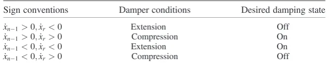
[image:4.595.132.466.649.714.2]Karnopp and Crosby (1974) in an attempt to reduce the response of vehicles using semi-active suspen-sion systems developed the famous skyhook control scheme. In this approach, the directionality con-dition of the forces is examined in order to determine whether a high or a low state of damping is required. Obviously, contrary to civil engineering structural control, automotive engineering control systems primarily aim to control the sprung mass (i.e. the mass supported by the damper) instead of the unsprung mass (the mass supporting the mass damper), making skyhook control not suitable for use on STMD-equipped structures. To overcome this limitation, Kooet al. (2004) altered the original skyhook controller design and extended its application on civil structures equipped with STMD vices. The resulting scheme is known as groundhook control. In a groundhook control scheme, de-pending on the motion of the mass of the damper and the structure, and without the loss of generality, four cases are identified and damper forces are calculated in accordance to that in Table I.
Table I. Groundhook control logic
Sign conventions Damper conditions Desired damping state _
xn1>0;x_r<0 Extension Off
_
xn1>0;x_r>0 Compression On
_
xn1<0;x_r<0 Extension On
_
Summarizing the conditions, the VBG control logic is mathematically captured by the following:
if x_n1x_r≥0 ∴csað Þ ¼t cmax; ifx_n1x_r<0 ∴csað Þ ¼t cmin: (9)
Alternatively, it is possible to replace the velocity of the unsprung mass by a primary system dis-placement term, resulting to DBG control, mathematically expressed as follows:
ifxn1x_r≥0 ∴csað Þ ¼t cmax; ifxn1x_r<0 ∴csað Þ ¼t cmin: (10)
3.2. Proportional-integral-derivative control
A PID controller works on the basis of calculating appropriate control actions based on a calculated feedback errore(t). For negative feedback control systems, the errore(t) defined as the difference of the output signal y(t) (i.e. displacement/velocity/accelerations) to a desired reference signal r(t) is mathematically expressed ase(t) =r(t)y(t). It is noteworthy that for structural applications, the de-sired state is the equilibrium; thus, the reference signalr(t) can take a value of zero. The controller’s objective is to minimize the error for the next iteration by appropriately adjusting the inputs to the structure. Using the textbook version of the PID controller, the desired control inputs that minimize the feedback error are calculated by the following (Astrom and Murray, 2012):
uað Þ ¼t Gproe tð Þ þGin∫ tf
0
e tð ÞdtþGd
de tð Þ
dx : (11)
The objective of the control algorithm is to calculate or tune the gainsGpro,Gin,Gdin such a way that given a feedback error at any time instanttwithin the control durationtf, the generated inputs will result into enhanced vibration performance. Demetriouet al. (2014) have previously found that simi-larly to any active control algorithm tailored for use on semi-active systems, PID controllers can be tuned‘aggressively’, i.e. allow for large gains that will minimize the rise-time and settling time for op-timal semi-active control behaviour. The large gains will in turn generate large control forces that can-not be achieved by conventional active devices. Yet, due to the nature of semi-active control devices such as magneto-rheological (MR) and electro-rheological (ER) dampers with response times in the range of a few milliseconds and their ability to limit the desired force by only varying their damping coefficient, aggressive PID gain tuning can be considered as a viable optimal approach.
3.3. Bang-bang control
A BANG controller used within energy dissipation devices, in contrast to a groundhook controller, makes use of both the relative displacement and velocity of the two ends of the device for the deriva-tion of the control acderiva-tion. When the relative velocity and displacement are in the same direcderiva-tion, the controller produces a force that increases the friction in the device, and in a manner work like a con-ventional brake that dissipates energy. When the relative velocity and displacement are in opposite di-rections, the force is eased in order to allow the device to move with reduced restriction. The control law can be mathematically expressed as:
if sgnð Þ ¼ xr sgnð Þx_r ∴csað Þ ¼t cmax; (12)
if sgnð Þ ¼xr sgnð Þx_r ∴csað Þ ¼t cmin: (13)
3.4. Linear quadratic regulator control
J¼∫
tf
0
zTð Þt Qz tð Þ þu tð ÞTRu tð Þdt: (14)
In Eq. (14),QandRare weighting matrices relating to the trade-off between control effectiveness and control energy consumption, respectively. By manipulating the magnitudes ofQandR, better vi-bration attenuation performance can be achieved at the expense of control effort (forces and energy de-mand) and vice versa. For example, a better disturbance rejection and minimization of the state error could be achieved by increasing the magnitude of the elements of theQmatrix relative to theRmatrix. In contrast, increasing the magnitude of theR relative to theQ matrix would yield smaller control forces, thus less control effort as well as reduced disturbance rejection. The values of elements of these matrices are selected such thatQis a positive semi-definite matrix andRis a positive definite matrix. By doing so, Eq. (14) will never yield a negative result. Once the weighting matrices have been ob-tained, the problem reduces to the classical optimal problem where the control gainGis calculated by
G¼ 1
2R
1FTP;
(15)
wherePis the Riccati matrix found by solving the algebraic Riccati equation:
PA1
2PFR
1FTPþATPþ
2Q¼0: (16)
Using the calculated control gain, the control action is calculated by
uað Þ ¼ t Gz tð Þ: (17)
4. NUMERICAL INVESTIGATION
4.1. Structural configuration
To illustrate the effectiveness of the different algorithms at alleviating structural response, the 76-storey benchmark wind-sensitive structure proposed by Yanget al. (2004) is considered. The build-ing has a square 42 m × 42 m cross-section, with a height-to-width aspect ratio of 7.3 and a low natural frequency that lends it the wind-sensitivity attribute.
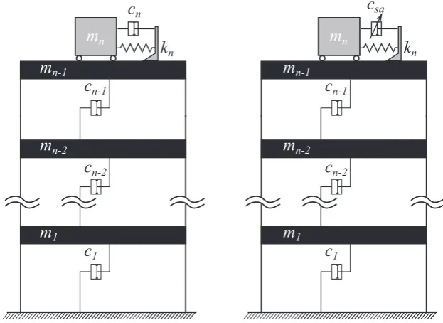
A simplified planarfinite element model of the structure is constructed by considering the portion of the building between two adjacent rigidfloors as a classical beam element of uniform thickness, lead-ing to 76 rotational and 76 translational DOFs. From these, all the rotational DOFs have been removed using static condensation, leading to a lumped mass sway model with DOFs, representing the displace-ment of each floor in the lateral direction. The resulting simulated structure has a total mass of 153 000 t, with thefirstfive frequencies at 0.16 Hz, 0.765 Hz, 1.992 Hz, 3.790 Hz and 6.395 Hz, and corresponding modal structural damping ratios of 1% calculated using Rayleigh’s approach. The re-sponse of the structure under a predefined wind load was investigated for two structural configurations: (a) structural model with an optimally designed TMD and (b) with an STMD at different control algo-rithm configurations. A schematic representation of the two different structural configurations is pre-sented in Figure 2.
Both the TMD and STMD devices comprise an inertial mass of 500 t that corresponds to 0.356% of the total structural mass. Because of the long period of the structural system and the associated motion generally governed by thefirst modal response, it was deemed appropriate to tune both the devices on the fundamental frequency of the structure (i.e.≈1 rad/s).
4.1.1. Wind excitation input
ASS1170.2-1989 (Australian Wind Code (Australian, 1989)) for winds with return period of 10 years. Thirty-two pressure panels (16 panels on either side of the test structure) were combined to give a single-pressure coefficient at the centre of each panel. The combined pressure coefficients are con-verted into across wind forces using:
F tð Þ ¼0:5ρU2CPrð Þt Apan; (18)
whereρis the density of air (kgm/m3),Uis the mean wind speed at the top of the building (m/s),Apan is the corresponding single panel area (m2) andCPr(t) is the dimensionless instantaneous combined
pressure coefficient (for more information on the exact details used for the derivation of the wind forces, the reader is referred to Samaliet al., 2004). Indicatively, Figure 3(a) and (b) illustrates the resulting dynamic part of the wind force for thefirst and last occupiedfloors along with the frequency content of each loading case. Evidently, any motion-correlated component is excluded from this wind force description (i.e. no interaction of the motion with the wind force is enabled).
4.2. Tuned mass damper and semi-active tuned mass damper damping tuning
[image:7.595.139.451.79.306.2]To this date, most of the tuning of the mechanical parameters of a TMD device is achieved via closed-form expressions derived from the minimization of the rms acceleration response of a single degree of freedom (SDOF) subjected to white noise or harmonic excitation. While this approach is broadly ac-cepted, representing civil engineering structures with an equivalent SDOF system can lead to signifi -cant errors in the estimation of their dynamic response. The problem amplifies when one considers the probabilistic nature of the knowledge of the system’s properties and the fact that the estimated proper-ties can vary with time (e.g. amplitude dependence, fluid–structure interaction etc.). Moreover, obtaining TMD mechanical parameters through the use of harmonic orflat spectrum inputs may not always yield optimum values (Ricciardelliet al., 2000). For these reasons, in this paper, because the motion of long period structures is generally governed by the first modal response, both the TMD and STMD are tuned to the fundamental frequency of the structure. On the other hand, tentative damping values are given to the damping devices based on existing formulas found in literature Figure 2. Ensemble of the structural configurations. (left) TMD-equipped structure and (right)
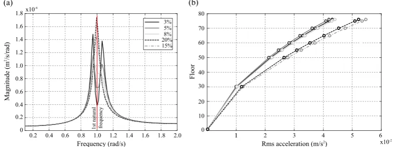
(Hartog, 1956; Ghosh and Basu, 2007), validated and adjusted when necessary through numerical/response optimization on the multi degree of freedom (MDOF) system. Following this prin-ciple, the numerical optimization procedure is based on minimizing the root mean square (rms) struc-tural acceleration response. Figure 4(a) shows the frequency response of the TMD-equipped structure under monoharmonic excitation around the tuning frequency of 1 rad/s for different damping ratios of the device, while Figure 4(b) shows the rms acceleration response of the structure at differentfloors, under wind excitation at the range of different damping ratios considered within Figure 4(a).
From these twofigures, it is evident that under both harmonic and wind excitation, the TMD-equipped structure has a better performance when the damping ratio is between 3% and 5%. By employing a sim-plex search algorithm for iterative/numerical response optimization of the rms acceleration response of the wind-excited 76-storey structure, a damping ratio of 4.7% was selected for the later analysis.
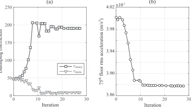
Similar to obtaining the appropriatefixed damping ratio for the TMD device, numerical optimiza-tion using the Nelder–Mead simplex search algorithm (Nelder and Mead, 1965) was employed for de-riving the maximum and minimum damping ratios for the STMD device. The implementation of the simplex algorithm was performed using MATLAB(MathWorks) response optimization toolbox. It is worth noting that similarly to the optimization of the TMD, the optimization of the STMD device is carried out solely on the basis of reducing the rms structural acceleration response of the last occupied floor (75th). Figure 5(a) and (b) shows how the algorithm alters non-uniformly thecmaxandcminvalues
at each of its iterations in an attempt to minimize the rms acceleration metric.
Figure 3. (a) Dynamic wind force time histories of last andfirst occupiedfloor and (b) frequency content of the wind excitationfluctuation.
Figure 4. (a) Power spectral density of the acceleration of the 7thfloor under harmonic loading and (b) rms acceleration response of differentfloors under the across wind loading derived from the static
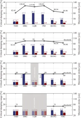
[image:8.595.102.500.67.220.2] [image:8.595.96.498.520.670.2]Figure 6 shows the resulting damping ratios for each algorithm configuration on the STMD-equipped system, along with the damper strokes obtained from the response optimization procedure. It is important to notice that the device stroke was implemented as an additional variable to the prob-lem in order to study the stroke limitations and interactions with the overall vibration mitigation per-formance it enables. The same scale was used throughout for comparative assessments.
It can be observed that as the stroke of the damper is progressively reduced, some of the algorithms could not achieve enhanced performance compared with the TMD-equipped system with respect to the optimization variable (rms acceleration). The phrase‘not-attainable’in Figure 6 is used to graphically illustrate the aforementioned argument. In this respect,‘not-attainable’demonstrates that the optimiza-tion of the LQR-STMD ensemble for strokes ≤80 cm, both minimum and maximum damping ratios converge to that of the TMD. Similarly, the DBG, LQR and PID control STMD ensembles for damper strokes ≤75 cm converge to the same minimum and maximum damping ratios of the passive TMD.
In addition to the aforementioned observations, the results of the optimization suggest that two cat-egories of algorithms can be distinguished. Namely these are a category of algorithms requiring a large high/low damping ratio (i.e.cmax/cmin) with a highcmaxcoefficient and a category of algorithms that
requires a small high/low damping ratio with relatively lowcmaxcoefficient. In the former category,
the DBG, PID and LQR algorithms are found, while the latter category contains the remaining two al-gorithms, the VBG and BANG.
4.3. Evaluation criteria
The comparison of the different control algorithms is based on the stationary response properties of the different controlled structures. Although the response of the system is primarily governed by thefirst mode of vibration, the rms and peak accelerations and displacements at different storeys extracted from the associated time-histories are used in order to capture the participation of different modes to the structural response. From the obtained values, 12 performance criteria were identified. Thefirst crite-rion,J1, appraises the ability of the control strategy to reduce rms accelerations at different building
heights:
J1 ¼maxðσ€x1;σ€x30;σ€x50;σ€x55;σx€60;σ€x65;σ€x70;σx€75Þ=σ€x75o; (19)
whereσ€x1is the rms acceleration of theithstorey andσ€x75ois the rms acceleration of the 75thfloor (last
[image:9.595.137.460.80.261.2]occupiedfloor) without any control action. The second performance criterion evaluates the average performance of sixfloors above the 49thfloor:
J2¼
1 6∑i σ€
xi=σ€xio
ð Þ; fori¼ 50;55;60;65;70;75; (20)
whereσ€xiois the rms of theithfloor without control. The third and fourth performance indices assess the
ability of the control system to reduce topfloor displacements:
J3¼σx76=σx76o; (21)
J4¼
1 7∑i σ
xi=σxio
ð Þ; for i¼ 50;55;60;65;70;75; (22)
[image:10.595.157.442.67.482.2]whereσxiis the rms displacement of theithfloor,σxiois the rms displacement of theithstorey without control andσx76ois the rms displacement of the 76thfloor without control. Thefifth and sixth indices take into account the rms stroke of the damper and the average power, respectively:
Figure 6. Optimal damping maximum–minimum ranges and damper strokes for the different STMD control scenarios for the cases (top to bottom) of uncapped damper strokes, strokes capped at 95 cm,
J5¼σxm=σx76o; (23)
J6 ¼
1
tf ∫ tf
0 _
xmð Þt u tð Þ
½ 2
dt
( )1=2
; (24)
in whichσxmis the rms stroke of the damper, x_mð Þt is the damper velocity andtfis the total time of integration. Similarly to the first performance indices, the next four criteria (i.e. J7toJ10) evaluate
the performance in terms of peak response quantities as follows:
J7¼max €xp1;x€p30;€xp50;€xp55;€xp60;€xp65;€xp70;€xp75
=€xp75o; (25)
J8¼
1 6∑i €
xpi; =€xpio;
for i¼ 50; 55; 60; 65; 70; 75; (26)
J9¼xp76=xp76o; (27)
J10 ¼
1 7∑i
xpi; =xpio
; for i¼ 50; 55; 60; 65; 70; 75; 76; (28)
where€xpiis the peak absolute acceleration of theithfloor with control and€xpiois the peak acceleration
of theithfloor without control. Similarly,xpiis the peak displacement of theithfloor andxpiois the peak displacement of theithfloor without control. The 11th criterion assesses the ability of the control strat-egy to minimize the stroke of the damper as follows:
J11¼xpm=xp76o; (29)
in whichxpmis the peak stroke of the actuator. The last criterion examines the control effort by calcu-lating the maximum required power by
J12¼maxjx_mð Þt u tð Þj: (30)
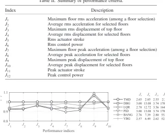
From the above defined criteria, it can be observed that the better the performance, the smaller the performance indicesJ1,J2,..,J12(Yanget al., 2004). Table II summarizes the 12 performance criteria
introduced for the benchmark problem at hand.
5. SIMULATION RESULTS
Two structural configurations consisting of passive and semi-active control devices are used for inves-tigating the performance of five different control algorithms on semi-actively controlled high-rise structures. Numerical optimization of the damping ratios for the TMD and STMD is carried out at dif-ferent damper stroke states as described in Section 4.2. The optimized devices are incorporated to the benchmark problem for numerical simulation. From this, the obtained structural response properties are used to calculate the 12 predefined performance indices for four different damper stroke cases. Figures 7–10 present the results of the comparison. In thesefigures, the performance indicesJ1toJ4
andJ7toJ10are associated with rms and peak response properties, respectively, while the remaining
four performance indicesJ5,J6,J11andJ12are associated with the stroke and the power consumed by
As probably expected, when the stroke of the damper is unrestrained the performance of the STMD-equipped structure at any control algorithm, configuration is superior on the majority of the perfor-mance objectives to that of the TMD-equipped one. This is illustrated through the lower values attained by performance indicesJ1toJ4andJ7toJ10excludingJ9. Note that for illustrative purposes,
[image:12.595.136.461.72.333.2]a scaled form was opted for all later graphs whereby the performance is scaled over the TMD performance.
Table II. Summary of performance criteria.
Index Description
J1 Maximumfloor rms acceleration (among afloor selection)
J2 Average rms acceleration for selectedfloors
J3 Maximum rms displacement of topfloor
J4 Average rms displacement for selectedfloors
J5 Rms actuator stroke
J6 Rms control power
J7 Maximumfloor peak acceleration (among afloor selection)
J8 Average peak acceleration for selectedfloors
J9 Maximum peak displacement of topfloor
J10 Average peak displacement for selectedfloors
J11 Peak actuator stroke
[image:12.595.144.451.83.251.2]J12 Peak control power
Figure 7. Scaled (over the TMD performance) performance indicesJ1,..,J4,J7,..,J10for uncapped
damper strokes.
Figure 8. Scaled (over the TMD performance) performance indicesJ1,..,J4,J7,..,J10for damper
strokes≤95 cm.
Figure 9. Scaled (over the TMD performance) performance indicesJ1,..,J4,J7,..,J10for damper
[image:12.595.121.471.382.464.2] [image:12.595.123.477.514.596.2]For the comparison between the different semi-active control configurations, the results from the uncapped damper stroke case indicate that it would be appropriate to divide the control algorithms into two categories. Thefirst category contains the more‘aggressive’algorithms, indicated by a higher perfor-mance index J11, and the second category of less ‘aggressive’ or more conservative algorithms that
achieve performance gains at the expense of lower damper strokes (see also Figure 6 in its uncapped variant). In this regard, the DBG, LQR and PID controllers are termed‘least-conservative’, while the BANG and VBG controllers are termed‘conservative’. Subsequently, when considering rms response properties (indicated byJ1toJ4), there is a noticeable difference between conservative and least
conser-vative algorithms. As a matter of fact, the latter category of algorithms achieves rms response reduction ranging from 6% to 8% when compared with the TMD-equipped structure and from 3% to 5% when com-pared with the STMD-equipped structure coupled with conservative algorithms. On the other hand, when peak response properties are considered (indicated byJ7toJ10), conservative algorithms better match the
performance of least conservative ones and even show superior performance when peak topfloor dis-placements are considered (indicated byJ9). It can be also observed that‘aggressive’tuning of the PID
controller (as explained in Section 3.2), makes the system behave identically to the system ensemble with a DBG controller. Nevertheless, different PID tuning methods for optimal behaviour are not exploited in this paper; thus, conclusions on the similarity of PID to other control algorithms cannot be definitive.
By restraining the damper stroke to a maximum allowable value of 95 cm as suggested by Yanget al. (2004), with reference to Figure 8, it can be observed that conservative algorithms succeed in reaching the performance of least conservative algorithms and even noticeably surpassing it in the case of peak re-sponse values, with the only exception of the LQR that appears to be more robust to the drop of damper strokes, maintaining better rms and peak response performance than every other algorithm. By further re-ducing the stroke to≤80 cm (Figure 9), similar observations can be made. However, the LQR that initially showed to be robust to the reduction of damper strokes failed to produce control actions that reduce the rms response of the structure without exceeding the stroke limit. This is evident from the fact that during the optimization, both damping coefficientscmaxandcminof the STMD device converged to a value of
4.7%, which is the optimum damping coefficient for the TMD device. In other words, at these (low) damper strokes, the LQR ensemble STMD cannot exceed the performance of a passive TMD with respect to the tuning property (rms acceleration). From the two conservative algorithms, the VBG shows better performance when compared with BANG both in terms of rms and peak responses
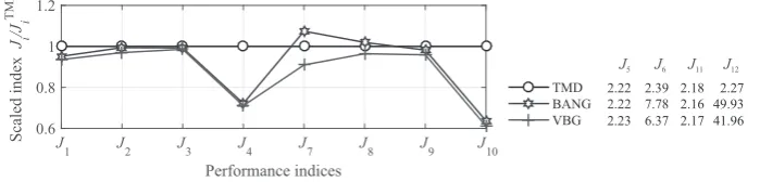
For damper strokes≤70 cm, none of the least conservative algorithms is able to produce control ac-tions that will reduce the performance objective set in Section 4.2. From the two remaining conserva-tive algorithms, VBG remains preeminent, while the BANG-STMD ensemble demonstrated inferior performance compared with the TMD system with respect to peak acceleration response properties in-dicated by performance indexJ7andJ8.
From the abovefindings and with reference back to Figure 6, it is evident that regardless of the damper stroke, all three of the least conservative algorithms require high cmax damping ratios for
achieving optimum performance, while theircmincoefficient is set to a relatively low value. This
[image:13.595.125.475.73.157.2]ob-servation suggests that least conservative algorithms make better use of the minimum damping ratio for increasing stroke (and thus optimally increase the velocity of the damper so that the damping force is also increased), and thoroughly use their high damping only when necessary. This is similar to re-ducing the damping ratio of the passive device (thus increasing the stroke) up to a point where no more performance can be gained. Supporting this observation, the results obtained from the optimization of Figure 10. Scaled (over the TMD performance) performance indicesJ1,..,J4,J7,..,J10for damper
minimum and maximum damping ratios for the cases of damper strokes≤95 cm, least conservative al-gorithms restrain the stroke by increasing thecmincoefficient while at the same time attempt to
main-tain the cmax coefficient close to the optimal. Undoubtedly, in order to maintain the performance of
least conservative algorithms close to the optimal, the resulting largecmax dictates the requirement
of large forces (and in turn control power indicated by performance indexJ6andJ12), which in turn
influence the size and number of devices required for control.
6. CONCLUDING REMARKS
A variety offixed parameter control algorithms proposed for semi-actively controlled structural sys-tems have been evaluated for use on high-rise structures incorporating STMD devices, through numer-ical simulations on a wind-excited 76-storey benchmark structure. The implementation of each algorithm was conducted based on available measurements of the structural system including absolute accelerations, displacements and velocities. The STMD-equipped structure at each of the algorithm configurations resulted in an improved performance when compared with the best passive case, with only exception the case of peak displacements in which the passive system was superior to the semi-active one. Still, for the semi-active case, the response of the structure varied significantly, de-pending on the choice of algorithm. In this regard, it is found that when no consideration is given on the damper strokes, three of these algorithms are found to be most suited for use with STMD on wind-excited structures. The LQR, the DBG and the PID that maximize damper strokes, thus termed
‘least-conservative’, achieved significant response reductions. On the other hand, it has been demon-strated that by progressively reducing the damper strokes, the remaining two algorithms, the VBG and BANG, the algorithms that significantly restrain the damper strokes and thus termed‘conservative’ managed to reach and even surpass in some cases the performance of previously ‘best’algorithms. From the category of least conservative algorithms, the LQR was shown to be more effective for use on the structure of interest, yet the requirement for full state feedback that translates to additional state measurements and computational burdens suggests that DBG and PID might be practically superior. From the category of conservative algorithms, the VBG is shown to be unconditionally superior to the BANG. From this, it has been demonstrated that appropriate selection of a control algorithm can be considered as an alternative method of limiting damper strokes while maintaining expedient perfor-mance without the requirement of an external auxiliary damping device for limiting the stroke.
Finally, by investigating the tuning of the damping ratios for the different configurations, it is found that the main difference of the two categories of control algorithms is the requirement of the least con-servative algorithms for high damping ratios for achieving optimal behaviour, whereas concon-servative algorithms require significantly lower values. As a matter of fact, for relatively similar performance gains, a DBG would require a maximum damping ratio of 16% as opposed to 8% required by a VBG. This suggests that the choice of an algorithm from the latter category would translate to a re-duced size/number of auxiliary devices used, control forces and power, which in turn relate back to the practical applicability and cost of the STMD device on high-rise structures.
ACKNOWLEDGEMENTS
The authors gratefully acknowledge EPSRC, UK (Grant No.EP/L504993/1) and the University of Leeds for thefinancial support to this study.
REFERENCES
Astrom KJ, Murray RM. 2012.Feedback Systems—An Introduction for Scientists and Engineers. Princeton University Press: New Jersey.
Australian S. 1989. Minimum Design Loads on Structures. II: Wind Loads.AS1170.2-1989.
Cao H, Reinhorn AM, Soong TT. 1997. Design of an active mass damper for a tall tv tower in Nanjing China.Engineering Struc-tures20: 134–143.
Casciati F, Rodellar J, Yildirim U. 2012. Active and semi-active control of structures—theory and applications: a review of re-cent advances.Journal of Intelligent Material Systems and Structures23: 1181–1195.
Demetriou D, Nikitas N, Tsavdaridis KD. 2014. Performance of proportional-integral-derivative controlled variable damping tuned mass dampers. Proceedings of the 6th International Conference of Structural Control, July, Barcelona, Spain. Frahm H. 1911.Device for damping vibration of bodies. United States patent application. Patent number 989 958.
Ghosh A, Basu B. 2007. A closed-form optimal tuning criterion for TMD in damped structures.Structural Control and Health Monitoring14: 681–692.
Hartog D. 1956.Mechanical Vibrations. McGraw-Hill Book Company: New York.
Hrovat D, Barak P, Rabins M. 1983. Semi-active versus passive or active tuned mass dampers for structural control.Journal of Engineering Mechanics, ASCE109: 691–705.
Jansen M, Dyke SJ. 2000. Semi-active control strategies for MR dampers: a comparative study.Journal of Engineering Mechan-ics, ASCE126: 795–803.
Kang J, Kim HS, Lee DG. 2011. Mitigation of wind response of a tall building using semi-active tuned mass dampers.The Struc-tural Design of Tall and Special Buildings20: 552–565.
Karnopp DC, Crosby MJ. 1974. Vibration control using semi-active force generators.Journal of Engineering for Industry5: 619–626. Kawaguchi A, Teramura A, Omote Y. 1992. Time history response of a tall building with tuned mass damper under wind force.
Journal of Engineering and Industrial Aerodynamics.41-44: 1949–1960.
Koo JH, Murray TM, Setareh M. 2004. In search of suitable control methods for semi-active tuned vibration absorbers.Journal of Vibration and Control10: 163–174.
Liu MY, Chiang WL, Hwang JH, Chu CR. 2008. Wind induced vibration of high-rise building with tuned mass damper includ-ing soil structure interaction.Journal of Wind Engineering and Industrial Aerodynamics96: 1092–1102.
Marian L, Giaralis A. 2014. Optimal design of a novel tuned mass–damper–inerter (TMDI) passive vibration control confi gura-tion for stochastically support-excited structural systems.Probabilistic Engineering Mechanics38: 158–164.
Nelder J, Mead R. 1965. A simplex method for function minimization.Computer Journal7: 308–313.
Pinkaew T, Fujino Y. 2001. Effectiveness of semi-active tuned mass dampers under harmonic excitation.Engineering Structures 23: 850–856.
Ricciardelli F, Occhiuzzi A, Clemente P. 2000. Semi-active tuned mass damper control strategy for wind-excited structures.
Journal of Wind Engineering and Industrial Aerodynamics88: 57–74.
Sadek F, Mohraz B. 1998. Semiactive control algorithms for structures with variable dampers.Journal of Engineering Mechan-ics981-990.
Samali B, Kwok K, Wood G, Yang J. 2004. Wind tunnel tests for wind-excited benchmark building.Journal of Engineering Mechanics, ASCE130: 447–450.
Soong TT. 1990.Active Structural Control: Theory and Practice. John Wiley & Sons: New York.
Wu Z, Soong TT. 1996. Modified bang-bang control law for structural control Implementation.Journal of Engineering Mechan-ics, ASCE122: 771–777.
Xu YL, Samali B, Kwok KC. 1992. Control of along-wind response of structures by mass and liquid dampers.Journal of En-gineering Mechanics118: 20–39.
Yang NY, Agrawal AK, Samali B, Wu JC. 2004. Benchmark problem for response control of wind-excited tall buildings. Jour-nal of Engineering Mechanics, ASCE130: 437–446.
AUTHORS’BIOGRAPHIES
Demetris Demetriouis a senior PhD student in structural dynamics and control at the School of Civil Engineering at the University of Leeds, UK. He received his MEng and BEng in structural engineering from the University of Leeds in 2013. His research interests include structural control, health monitoring and identification analysis.
Nikolaos Nikitas is a lecturer on structural dynamics at the School of Civil Engineering of the University of Leeds, UK. He received two PhDs, one from the University of Edinburgh and one from the University of Bristol. His expertise lies within the fields of aeroelasticity, structural health monitoring, inverse analysis and dynamic modelling of structures, while he is also fond of studies relevant to complexity and chaos.