UNIVERSITI TEKNIKAL MALAYSIA MELAKA
DEVELOPMENT OF FOGGING ROBOT BY USING ARDUINO
UNO AND HC-05 BLUETOOTH MODULE
This report submitted in accordance with requirement of the UniversitiTeknikal Malaysia Melaka (UTeM) for the Bachelor Degree of Electrical Engineering
Technology (Industrial Automation and Robotic) with Honours
by
KHAIROL RIDWAN BIN MUHAMMAD B071310454
920104-08-6139
UNIVERSITI TEKNIKAL MALAYSIA MELAKA
BORANG PENGESAHAN STATUS LAPORAN PROJEK SARJANA MUDA
TAJUK: Development of Fogging Robot by Using Arduino Uno and HC
Bluetooth Module SESI PENGAJIAN: 201
Saya KHAIROL RIDWAN BIN M
mengakumembenarkanLaporan PSM inidisimpan di PerpustakaanUniversitiTeknikal Malaysia Melaka (UTeM) dengansyarat
1. Laporan PSM adalah hak milik
2. Perpustakaan Universiti Teknikal Malaysia Melaka dibenarkan membuat salinan untuk tujuan pengajian sahaja dengan izin penulis.
3. Perpustakaan dibenarkan membuat salinan laporan PSM ini sebagai bahan
pertukaran antara institusi pengajian tinggi.
4. **Silatandakan (
SULIT
TERHAD
TIDAK TERHAD
(TANDATANGAN PENULIS)
AlamatTetap:
F2-8 Kuarters Kelas F IPD Pendang
06700 Pendang;
Kedah Darul Aman.
** JikaLaporan PSM ini SULIT atau TERHAD, sila lampirkan surat daripada pihakberkuasa/organisasi berkenaan dengan menyatakan sekali sebab dan tempoh laporan PSM ini
SULIT atau TERHAD.
UNIVERSITI TEKNIKAL MALAYSIA MELAKA
BORANG PENGESAHAN STATUS LAPORAN PROJEK SARJANA MUDA
Development of Fogging Robot by Using Arduino Uno and HC
2016/17 Semester 1
KHAIROL RIDWAN BIN MUHAMMAD
mengakumembenarkanLaporan PSM inidisimpan di PerpustakaanUniversitiTeknikal Malaysia Melaka (UTeM) dengansyarat-syaratkegunaansepertiberikut:
Laporan PSM adalah hak milik Universiti Teknikal Malaysia Melaka dan penulis. Perpustakaan Universiti Teknikal Malaysia Melaka dibenarkan membuat salinan untuk tujuan pengajian sahaja dengan izin penulis.
Perpustakaan dibenarkan membuat salinan laporan PSM ini sebagai bahan antara institusi pengajian tinggi.
)
TIDAK TERHAD
(Mengandungimaklumat yang
berdarjahkeselamatanataukepentingan Malaysia sebagaimana yang termaktubdalam AKTA RAHSIA
RASMI 1972)
(Mengandungimaklumat TERHAD yang telahditentukanolehorganisasi/badan di
manapenyelidikandijalankan)
(TANDATANGAN PENULIS)
8 Kuarters Kelas F IPD Pendang;
Disahkan
(TANDATANGAN PENYELIA)
Cop Rasmi:
** JikaLaporan PSM ini SULIT atau TERHAD, sila lampirkan surat daripada pihakberkuasa/organisasi berkenaan dengan menyatakan sekali sebab dan tempoh laporan PSM ini
UNIVERSITI TEKNIKAL MALAYSIA MELAKA
BORANG PENGESAHAN STATUS LAPORAN PROJEK SARJANA MUDA
Development of Fogging Robot by Using Arduino Uno and HC-05
mengakumembenarkanLaporan PSM inidisimpan di PerpustakaanUniversitiTeknikal syaratkegunaansepertiberikut:
Universiti Teknikal Malaysia Melaka dan penulis. Perpustakaan Universiti Teknikal Malaysia Melaka dibenarkan membuat salinan
Perpustakaan dibenarkan membuat salinan laporan PSM ini sebagai bahan
berdarjahkeselamatanataukepentingan Malaysia sebagaimana yang termaktubdalam AKTA RAHSIA (Mengandungimaklumat TERHAD yang
telahditentukanolehorganisasi/badan di
Disahkanoleh:
(TANDATANGAN PENYELIA)
ii
DECLARATION
I hereby, declared this report entitled “Development of Fogging Robot by Using Arduino Uno and HC-05 Bluetooth Module” is the results of my own research
except as cited in references.
Signature : ………...
Name : ………...
iii
APPROVAL
This report is submitted to the Faculty of Engineering Technology of UTeM as a partial fulfillment of the requirements for the degree of Bachelor of Engineering Technology (Industrial Automation and Robotic) with Honours. The member of the supervisory is as follow:
……….
iv
ABSTRACT
v
ABSTRAK
vi
DEDICATIONS
Special dedicated to
My beloved parents, My wife and my son, My friend and my siblings,
vii
ACKNOWLEDGMENTS
A special thank for those who helping me to accomplish my PSM project especially to my project supervisor, Mr. Mohamad Haniff Bin Harun for helping and guiding me to completing this project. With his supportive attitude this project goes successfully by achieving the entire project objective. The success of this project is highly influenced by his information, suggestions and ideas
I also would like to take this opportunity to express my deepest gratitude to my family and friends who have given me support during my academic years. Without them, I might not be able to finish the project.
viii
TABLE OF CONTENT
DECLARATION ii
APPROVAL iii
ABSTRACT iv
ABSTRAK v
DEDICATION vi
ACKNOWLEDGMENTS vii
TABLE OF CONTENTS vii
LIST OF TABLES xi
LIST OF FIGURE xii
LIST OF ABBREVIATIONS, SYMBOLS AND NOMENCLUTURES xiv
CHAPTER 1 1
INTRODUCTION 1
1.0 Project Background 1
1.1 Problem Statement 2
1.2 Objective 2
1.3 Project Scope and Limitations 3
CHAPTER 2
LITERATURE REVIEW 4
2.0 Introduction 4
2.1 Journal 4
ix
2.1.5 Study and Development of Android Controlled Wireless Pole Climbing
Robot (Megalingam et al. 2015) 8
2.1.6 An Implementation of Mobile Control Room Environment in Android Platform for Industrial Application (Alexander 2015) 9 2.1.7 Zigbee-assisted Mobile Robot Gardener (Chang et al. 2013) 10 2.1.8 A Study of Bluetooth Application for Remote Controlling Of Mobile
Embedded Systems (Silva et al. 2012) 11
2.1.9 Solar-Powered Android-Based Speed Control of DC Motor via Secure
Bluetooth (Khanna 2015) 11
2.1.10 Mission-Oriented Design: A Fully Autonomous Mobile Urban Robot
(Zhang et al. 2010) 11
2.1.11 A11 Design and Implementation of a 4WS4WD Mobile Robot and Its
Control Applications (Lin et al. 2013) 12
2.1.12 A Main Algorithm of Mobile Robot System Based On The
Microcontroller Arduino (Denysyuk & Teslyuk 2013) 13 2.1.13 Remote Control Robot Using Android Mobile Device
(Nádvorník & Smutný 2014) 14
2.1.14 Design of an Arduino-based Smart Car (Wang et al. 2015) 15 2.1.15 AndroRC: An Android Remote Control Car Unit for Search Missions
(Jing et al. 2012) 15
2.2 Conclusion 17
CHAPTER 3
METHODOLOGY 18
3.0 Introduction 18
3.1 Methodology 18
3.1.1 Mechanical Development 20
3.1.2 Electrical Development 21
3.1.3 Documentation 22
3.2 Mechanical and Electrical Hardware 23
3.2.1 Arduino UNO 23
3.2.2 MDD10A Dual Channel Motor Driver 25
x
3.2.4 HC-05 Bluetooth Module 27
3.2.5 Caster Wheel 28
3.2.6 Plastic Wheel for Spg30/Spg50 (80mm) 28
CHAPTER 4
RESULT & DISCUSSION 30
4.0 Introduction 30
4.1 Mechanical And Electrical Development Of Mobile Fogging Robot 30 4.2 Studies On The Effect Of Load Toward The Velocity Of The Mobile
Robot 35
4.3 Experiemnt on the Bluetooth Communication Performance 39
4.4 Analysis on Fogging Mechanism 41
CHAPTER 5 43
CONCLUSION 43
5.0 Introduction 43
5.1 Conclusion 43
5.2 Recomendation 45
REFERENCE 46
APPENDIX A 48
xi
LIST OF TABLE
Table 3.1: Arduino UNO technical specification 23 Table 3.2: Table 3.2 SPG50-60K technical specification 24
Table 4.1: The Response Of Velocity When Carried A Load In Cement Surface 35 Table 4.2: The Response of Velocity When Carried A Load In Road Surface 36 Table 4.3: The Ability Of The Fogging Robot On The Off-Road Surface. 38 Table 4.4: The Time Response of Bluetooth Module 39
xii
LIST OF FIGURES
Figure 2.1: Control panel Schematic Diagram 5
Figure 2.2: Robot Schematic Diagram 5
Figure 2.3: Mobile robot platforms 6
Figure 2.4: Two-Parallel Crawler Robot system schematic diagrams 7
Figure 2.5: Pole Climbing Robot system schematic diagrams 9
Figure 2.6: Mobile Control Room Environment systems 10
Figure2.7: Zigbee-assisted Mobile Robot Gardener system 10
Figure2.8: CPU unit of Fully Autonomous Mobile Urban Robot 12
Figure2.9: CPU unit of Fully Autonomous Mobile Urban Robot 12
Figure2.10: The 4WS4WD mobile robot 13
Figure2.11: Algorithm of the robot work. 14
Figure2.12: Arduino-based Smart Car 15
Figure2.13: AndroRC flow chart 16
Figure 3.1: Flow Chart 20
Figure 3.2: The chassis of Car-Like 4 Wheeled-Mobile Robot with the Front
Differential-Wheels Drive on the SolidWork 2013 21
Figure 3.3: 3 Electrical hardware configuration layouts 21
xiii
Figure 3.5: Arduino UNO 24
Figure 3.6: MDD10A Dual Chanel Motor Driver 25
Figure3.7: SPG50-60K DC Gear Head Motor 26
Figure3.8: HC-05 Bluetooth modules 27
Figure3.9: Caster Wheel 28
Figure3.10: Plastic Wheels for Spg30/Spg50 (80mm) 29
Figure 4.1: Final Design of Fogging Robot by using SolidWork 2013 software 30
Figure 4.2: Electrical Hardware in the Control Element Box 31
Figure 4.3: Mobile Robot 32
Figure 4.4: Android Base Applications On Smartphone. 26
Figure 4.5: Flow Control By Using Manual Valve. 34
Figure 4.6: The Velocity Versus Load Graph on Cement Surface 36 Figure 4.7: The Velocity versus Load Graph on Road Surface 37
Figure 4.8: The Fogging Robot Travelled On The Off-Road Terrain With 5kg Load 38
Figure 4.9: Bluetooth Module Performance experiment 39
Figure 4.10: The Graph Of The Distance Versus Time Response Of The Fogging
Robot 40
Figure 4.11: Mineral Oil Fogging Performances 41
Figure 4.12: Water Fogging Performances 42
xiv
LIST OF ABBREVIATIONS, SYMBOLS AND NOMENCLATURE
1
CHAPTER 1
INTRODUCTION
1.0 Project Background
2 1.1 Problem Statement
Currently in Malaysia, the most common fogging process was the thermal fogging machine. The machine will be carried by the machine operator to fog the suspected area. Based on the datasheet from the machine produced, the manufacturers strongly recommended wearing the personal protective equipment (PPE). This was because main hazards of this machine are the heat and the noise produced by the machine. Moreover, the chemical reaction between the liquid and the pesticide will also can cause harm to the machine operator. Due to the higher demand from the suspected area, it will limit the vector control because of the large area need to be covered.
1.2 Objective
In order to minimize the hazard towards the operator, overcome the labour issue and make the fogging process easier, the Fogging Robot will be develop with the three main objectives which is:-
i. To develop the mechanical and electrical part of the mobile Fogging Robot
ii. To develop the fogging mechanism so that it can be attached to the mobile Fogging Robot
3 1.3 Project Scope and Limitations
Hardware design:
i. Mechanical- For the mechanical main structure, this project will be used the mild steel bar 1inch x 1 inch as the mobile robot chassis material. There are also several basic mechanical component will design and attached to this fogging robot like tire, main body and others important mechanical component. This project will also use corrugated sheets as the main body of the fogging robot.
ii. Electrical and electronic - The main electrical component for this project was the SPG30-60K DC gear head motor. The DC gear head motor was used as the main driver of this fogging robot. As the controller, this fogging robot will used the Arduino UNO as the main board and HC-05 module as the Bluetooth transmission system. For driving the DC gear head motor, the MDD10A’s Cytron technologies Dual Channel 10A DC Motor Driver will be used.
Software design - To program the Arduino UNO main board, the Arduino IDE software will be used. Besides that, to develop the Android application on the Smartphone, this project will used MIT App Inventor 2
Analysis design and limitation:
Load test experiment – this experiment to test the ability of the fogging robot ability to carry the load. This experiment is important to the fogging robot because the robot must have the ability to carry the fogging mechanism system which is the heaviest part in this fogging robot.
4
CHAPTER 2
LITERATURE REVIEW
2.0 Introduction
Basically, in this chapter will discussed on the finding that have been done on the previous related project and experiment. The findings were gained from the journal reading, website and the previous project. The finding will be focused on the mobile robot development, the controller and also the wireless Bluetooth connection and Android app development as references to the fogging robot development.
In the others hands, beside as the references of the project the literature review of this fogging robot will also give some idea and guide line on the development of this fogging robot.
2.1 Journal
5
2.1.1 Mobile Inspection Robot for Heating, Ventilation and Air Conditioning (HVAC) Ducting Systems(Aisha et al. 2015)
[image:20.595.262.410.454.554.2]The main objective of this project is to develop a robot that capable to do inspection the condition of ventilation ducts. The methods used for this project are this project will divided into two major part of development which is control panel part and robot part. The main controller of this project was the Raspberry Pi. It also used the Arduino UNO with the internet shield to below:-
Figure 2.1 Control panel Schematic Diagram
Firgure 2.2 Robot Schematic Diagram
6
As the conclusion, the robot was able to do the inspection on the HVAC ducting system. Moreover, the robot was able to send the forward vision feedback to the user. Others than that, the robot also able to be attached the mechanical gripper and brushes. Therefore, the robot can retrieve hazardous or suspicious item from the duct and also clean the duct if necessary.
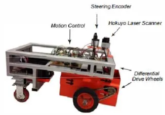
2.1.2 Wall Following Control Algorithm for a Car-Like Wheeled-Mobile Robot with Differential-Wheels Drive(Prayudhi et al. 2015)
The main objective of this project is to develop a car-like wheeled-mobile robot with differential–wheels drive. Other than that, the robot also developed to be a wall followed mobile robot. Besides that, the researchers also design the control algorithm of the robot. In this project, the researchers introduced are new type of the mobile robot design which car-like wheeled-mobile robot with differential-wheels drives.
[image:21.595.257.420.580.694.2]The mobile are design with the front wheel performing the differential drive motion and also working as the steering mechanism to the mobile robot. For the rear side, two fixed wheels are attached for followed the movement the front wheels. For measuring the turning angle, the robot are attached the encoder to the steering mechanism. Furthermore, the mobile also equipped with the laser range finder sensor to detected the obstacle, measured the distance and also to measure the orientation of the robot to the wall. The mobile platform is as shown in Figure 2.3.
7
Based on the experiment and simulation done by the researcher, the robot move was very precise since the robot has the feedback signal to correct the error.
2.1.3 Development and Evaluation of Two-Parallel Crawler Robot by Using Proportional Controller(Azni et al. 2015)
[image:22.595.234.446.312.525.2]The main objective of the project is to design and develop the crawler type robot that was able to pass several types of terrain. Other than that, the researcher want to analyzed and evaluate the performed of the crawler robot by using the Proportional controller in term of accuracy and repeatability. The robot system schematic as shown below in Figure 2.4:-
8
the highest speed. Moreover, this crawler Robot compensated system is effective on the regular terrain rather than grass train. Therefore, this system is not suitable to the sub-urban area.
2.1.4 Navigation Method of PLC Based Mobile Robot (Saffar et al. 2015)
The main objective of this project is to develop an algorithm and analyze the navigation of mobile robot using PLC. The mobile was designed base on the 3 wheels 2 wheels drive (3W2WD) mobile robot. This means that the mobile robot wills consisting 3 main wheels which single wheels at the front and the others two will be at the rear side of the mobile robot. For this project the front wheels used the castor wheel also acting as the steering to the mobile robot while the others rear wheel will drive the mobile robot. For controlling the mobile robot, this project used the Keyence PLC KV-16T. This mobile robot also will equipped with the three diffuse sensor, relay, two DC motor, switches, indicator lamp, emergency stop button and 12VDC batteries. To investigate the navigation of this robot, the navigation experiment was setup by the researcher. Base on the experiment done by researcher, the mobile robot able to be controlled by the PLC.
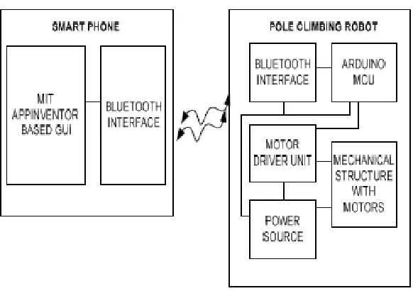
2.1.5 Study and Development of Android Controlled Wireless Pole Climbing Robot (Megalingam et al. 2015)
9
Figure 2.5 Pole Climbing Robot system schematic diagrams
Base on the schematic diagram, the climbing robot are divided into two major part which is smart phone controller part and pole climbing robot part. For the smart phone controller part, this project used the MIT AppInventor to create the Android base GUI. The smart phone will connected to the pole climbing robot by using the Bluetooth interface that are already build up inside the smart phone. The HC-05 Bluetooth module has used in this project to the interfaced the Bluetooth wireless connection between the smart phone and the pole climbing robot. The main controller for this pole climbing robot is the Arduino UNO. After receiving the data from HC-05 Bluetooth module, the Arduino UNO will interpret the data into the mechanical movement though the motor driver and DC motor.
2.1.6 An Implementation of Mobile Control Room Environment in Android Platform for Industrial Application (Alexander 2015)