Int. J. Electrochem. Sci., 14 (2019) 329 – 345, doi: 10.20964/2019.01.21
International Journal of
ELECTROCHEMICAL
SCIENCE
www.electrochemsci.orgElectro-catalytic Reduction of Aqueous Nitrates using Cu-Sn
and Cu-Pd Cathodes
Bernd Weber1,*, Alma Chávez2, Ernst A. Stadlbauer3
1 Faculty of Engineering, Autonomous University of the State of Mexico, Cerro de Coatepec s/n Col.
San Buenaventura, C.P. 50130, Toluca, State of Mexico, Mexico.
2 Institute of Engineering, National Autonomous University of Mexico, Av. Universidad 3000, Col.
Copilco el alto, C.P. 04510, Coyoacán, Mexico City, Mexico.
3 Department of Math, Natural Science and Computer Science, University of Applied Sciences THM,
Campus Giessen, 35390 Giessen, Germany.
*E-mail: bweber@uaemex.mx
Received: 18 July 2018 / Accepted: 14 September 2018 / Published: 30 November 2018
Water treatment systems are used globally to reduce environmental impacts or to provide potable water, thus fulfilling established water quality standards. Electrocatalytic nitrate removal is a promising tool to address upcoming problems related to nitrate contamination. This study compares the employment of a low cost CuSn6 based catalyst with a noble metal Cu - Pd catalyst in a laboratory and a continuously operating pilot apparatus to treat nitrate contaminated water from a well. In contrast with common applications, a saturated carbonic acid was used as the anolyte solution, which stabilized the pH in the anode compartment as well as in the cathode compartment. The best performance, as determined by nitrate removal and nitrogen transfer into the gas phase, was reached with a specific current of 1.16 A m-2 for the laboratory apparatus and 1.53 A m-2 for the pilot plant apparatus. However, other parameters such as pH (influenced by anolyte solution) and catalyst selection also had an impact on the nitrate reduction performance with the consequence that process optimization should be realized on-site while running a pilot plant. Process gas analysis by mass spectroscopy revealed the presence of hydrogen, which suggests that a combination of the system with heterogeneous catalysts should be used for additional nitrogen reduction at potential free surfaces.
Keywords: Copper-tin electrode; Carbonic acid; Palladium-Copper Catalyst; Groundwater
1. INTRODUCTION
and contributes to mitigation of human impacts that originate in urban areas with high population density. At the same time, food production for the human population leads to the negative impact of nutrient leaching into water bodies, due to excess use of fertilizer with the intent of maximising land productivity. In addition, recent strategies to produce biofuels in parallel further drives fertilizer use and impact. Therefore, there is a need for potable water to be treated for ubiquitous nitrate contamination because its negative influences on human health. In Mexico there are no official reports on the percentage of wells contaminated with nitrates, however, problems are frequently observed when irrigation runoff is used to recharge aquifers, which exhibit nitrate concentrations of over 140 mg L-1 [1]. In the United
States of America, elevated nitrate concentration caused by anthropogenic activities is reported in 4.4% of monitored wells [2]. Germany reported nitrate contamination in 49.5% of 739 monitoring wells to the European Union, while in the European Union only 14.4% of wells exceeded the human health benchmark of 50 mg NO3- L-1 [3]. In Germany, which has a dense potable water distribution system, the
simplest way to deliver potable water that fulfils legislative requirements is by blending contaminated streams with unpolluted streams. However, frequently potable water has to be treated by applying alternative technologies like ion-exchange, electrodialysis, or membrane separation [4]. Each of these systems only removes nitrate from the potable stream and creates a parallel second nitrate enriched stream, for membrane separation, or a highly concentrated nitrate stream, for ion-exchangers running in regenerating mode.
As with the denitrification step in biological treatment, nitrates can be reduced to molecular nitrogen using a catalytic process as described in an early work by Vorlop and Tacke [5]. In contrast, the hydrogen necessary for the reduction reaction can be produced in situ when using electrolysis. In this electrochemical reaction the surface of the cathode has catalytic properties and consequently the nitrate adsorbed to the cathode is reduced. Such an experimental setup was patented by the authors [6] and further investigated by different research groups [7-9]. Nitrate reduction using platinum cathodes in strong alkaline solutions was reported even earlier [10-13], while nitrate reduction using platinum in acidic media is also possible and reported frequently [14]. Other materials with catalytic properties for nitrate reduction in acidic solutions are Pt/Rh, Pt/Ir, Pd-Sn, Ag, Au and Cu [15, 16]. However, potable water production calls for catalysts with the ability to reduce nitrates in neutral media.
Studies on nitrate reduction in neutral media have shown that the following metals can be used: copper [17], iridium [9, 18], palladium [19], rhodium [20], and alloys of these elements with Pt, Zn and Sn [21]. In spring water, other ions present act in competition with NO3- and NO2- for adsorption to the
The search for a novel catalyst for electrocatalytic nitrate reduction is ongoing. For example, Su et al. [26] applied micro-architectured electrodes, finding that nitrate reduction is a function of surface morphology. Boron doped Diamond showed high selectivity and resistance to aggressive media as reported by Martinez et al. and Kuang et al. [27, 28], however high costs for such a catalyst limits its application to special treatments [29]. Beyond that, recent investigations report on technical modifications used to obtain process improvements. One such way for process improvement is to remove nitrates by the use of suspended Pd-Cu catalysts in the cathodic compartment making use of excess hydrogen produced on the cathodes [30]. When the membrane is doted on both sides with metallic/catalytic conductors the potential over the electrodes is reduced and these systems run with higher efficiency [31-33].
An inconvenience for all nitrate reduction processes is an increase in pH. Due to both the dependency of the pH on the presence of the various nitrogen compounds in the water [34] and the requirements stipulated in water regulations, stabilization of pH is necessary. One option for pH stabilization is the use of dissolved CO2 and results from its injection into the cathodic compartment
have been reported by Hasnat et al. [33]. However, dissolved CO2 can also be used to stabilize pH in the
anodic compartment when injected into the anodic compartment. This arrangement was part of this study, which was realized to determine the operation performance of catalytic active cathodes as part of an electro dialysis unit with the focus on nitrate reduction in potable water in a laboratory scale batch reactor and a continuously fed pilot scale plant.
2. MATERIALS AND METHODS
2.1. Laboratory Conversion Apparatus
At the laboratory scale, the anode and cathode were separated by an NAFION® ZO012 ion
exchange membrane (NE424 W Fabric), Du Pont N.C. with an effective surface area of 0.0589 m2 (210 mm x 290 mm). The sandwich constructions contained two compartments of cathodic solution and one compartment of anodic solution. The two anodes were each an expanded titanium metal mesh (Size 10 mm x 5 mm and 1 mm x 1 mm rhombic wire) plated with 2.5 µm of platinum. A polypropylene spacer mesh (0.7 mm wire size and 3 mm orifice size) was placed on both sides of the membrane.
All electrodes had a size of 206 mm x 286 mm. These active components were fixed into a three layered frame made from polyvinylchloride with a ployacrylic plate placed on the front. Additionally, a 4 mm thick viton ring was placed into a notch on the frame to seal the frames and fix the membranes. Each frame had two spouts at the inlet and outlet consisting of connected silicon hoses to circulate flow between the conversion apparatus and storage tanks, each with a capacity of 10 L. Circulation flow was induced by a centrifugal pump and controlled with a rotameter. The anode and cathode were connected to an PS 405 D adjustable power supply (0-40 V and 0.01-5 A) from Conrad Electronic, Hirschau, Germany.
The conductivity and temperature of the solution were measured online with the LF95 from WTW Company, Weilheim, Germany. The pH value was determined with the pH 530 from the WTW Company. Flow of the anode and cathode solution was measured with two flow rotameters KSK-2200 from Kobold Messring Company, Hofheim, Germany placed in the silicon hoses vertically above the centrifugal pumps.
2.2. Pilot Plant Conversion Apparatus
The sandwich element used in the pilot plant was a stack of four anodic compartments and three cathodic compartments with the same size of membranes and electrodes as used in the laboratory equipment. The materials for anodes and cathodes were also the same as in the laboratory experiment. A PVC frame 30 mm thick established the thickness of the compartments, a photo of which shown in the hydraulic diagram of the pilot plant in Fig.1.
[image:4.596.72.538.460.658.2]
Each frame had an inlet and outlet hose nipple. The same power supply was used in the pilot plant. Circulation of the anodic and cathodic solution between the storage tanks and stack of electrodes was realized with two centrifugal pumps type MPN 115 from Schmitt-Kreiselpumpen GmbH & Co.KG, Ettlingen, Germany. The dosing of nitrate contaminated water was realized with a peristaltic pump from the Masterflex Company, East Bunker Court Vernon Hills, USA. Tubing material was Versilic®, form Saint-Gobain, Charney, France.
The online process measurements comprise the determination of pH in both the anodic and cathodic compartments with an orbisint CPS 11/12 electrode, temperature with Omnigrad TST42 (RTD 100), flow with Promag 33 A, conductivity with Mypro CLM 431, pressure with Cerabar S PMC 731 (all from Endress+Hauser Company, Rainach, Switzerland) and nitrate concentration with a Nitratax plus LXV237 electrode with a measuring range of 0.2 - 200 mg NO3- L-1 and 0 - 50 mg NOx- L-1 from
Hach Lange Company, Düsseldorf, Germany.
2.3. Test Procedure when Operating the Laboratory and Pilot Plant Apparatus
Nitrate reduction was realized with the laboratory apparatus in batch mode with an initial nitrate concentration of 1 mmol NO3- L-1. The nitrate solution in the storage tank (4 - 7 L volume) was forced
by the pumps through the cathode compartment and the nitrates were eliminated within 27 hours under the different process alterations. The recycle rate in the storage tank was about 25 times an hour. Several runs with different cathodes, specific currents, and anodic solutions were realized. By using two cathodic compartments, various combinations of the three materials (CuSn6, FE98 coated with Cu and FE98 coated with Cu and Pd) could be employed for nitrate degradation. The following runs were realized:
CuSn6 in both compartments
CuSn6 in one compartment and FE coated with Cu in the other compartment
CuSn6 in one compartment and FE 98 coated with Cu and Pd in the other compartment
FE98 coated with Cu and Pd in both compartments
Distilled water, water saturated with carbonic acid, and diluted sulphuric acid were used as the anodic solution for the four material combinations mentioned in the following concentrations: 0.01, 0.05 and 0.005 mol L-1.
Experiments under the influence of current (0.8, 0.98, 1.16 and 1.43 A m-2) were only realized for the CuSn6 cathodes and 0.05 mol L-1 of diluted sulphuric acid as the anodic solution.
Process performance was evaluated by evaluating the electron balance of nitrate removal, and nitrite and ammonium formation.
The pilot plant operated in batch and continuous mode. Only CuSn6 was employed as the cathode material in the pilot plant to ensure the use of low cost materials for the cathodes. Sulphuric acid diluted to a concentration between 0.002 and 0.005 mol L-1 was employed as the anodic solution, which was decided to allow for good conductivity.
pilot plant was higher than for the laboratory apparatus because in the pilot plant both sides of the cathode had an opposing anode.
The selected control parameter for the continuous operation was the nitrate concentration of the recirculation flow between the cathodic compartments and the storage tank, as determined by the Nitratax electrode. When the nitrate concentration fell below 25 mg L-1 a solenoid valve let freshwater flow in and an equal amount of recirculating water flowed out over a dam.
2.4. Water
The water was taken from a well at Reiskirchen-Hattenrod, Germany, which exhibited a variable nitrate concentration between 20 and 150 mg L-1.
2.5. Analytics
During operation, small samples were taken and the following measurements were realized:
Concentration of anions (chloride, fluorite, nitrate, nitrite and sulphate) by anion chromatography with a Dionex Series 4000i.
Ammonium concentration was determined photometrically with prepared LCK 304 test kits (measuring range 0.02 – 2 mg NH4+ /L) and LCK 305 kits (measuring range 1.3 – 15 mg NH4+ L-1)
from Hach Lange Company, Berlin, Germany.
Sporadically, the composition of the gas phase was analysed by mass spectroscopy form Balzers Company, Asslar, Germany.
2.6. Process Performance
The process performance can be described by the yield of nitrate reduced to molecular nitrogen, which requires 5 electrons for complete reduction, in relation to the total electrons transferred to the electrode. This relation is described by the following equation:
η𝑛𝑖𝑡𝑟𝑎𝑡𝑒 𝑟𝑒𝑚𝑜𝑣𝑎𝑙= 5 ∙ ∆𝑛(𝑁𝑂3
−) ∙ 𝐹
𝐼 ∙ 𝑡 ∙ 100% (1)
Where I is the current in A; Δn(NO3-) the nitrate eliminated in mol; F the Faraday constant 96845
As mol-1, and t operation time in s. When the nitrate is only reduced to nitrite, fewer electrons are consumed, but when ammonium is formed, more electrons are consumed. Also, secondary reactions, like the production of hydrogen, modifies the balance.
q𝑛𝑖𝑡𝑟𝑎𝑡𝑒 𝑟𝑒𝑚𝑜𝑣𝑎𝑙 =
𝑐(𝑁𝑂3−)
𝐼𝑛− 𝑐(𝑁𝑂3−)𝐸𝑓
𝐴𝑐𝑎𝑡ℎ𝑜𝑑𝑒∙ 𝑡
∙ 𝑉 (2)
Where c(NO3-) is the nitrate concentration in mg L-1 or mmol L-1; Acathode the geometric surface
area of the cathode in m2; V sample volume in L; and t operation time in hours for batch operation or V/t influent flow in L h-1.
3. RESULTS AND DISCUSSION
A screening of various metals was realized to determine the catalytic activity of the materials. For this, cathodes were either purchased when commercially available (e.g. Hastelloy Sheet) or galvanically coated similar to the previously described methods. The following metals did not show a nitrate reduction reaction under equal reaction conditions (neutral pH, 150 mA current, for 3 hours with initial NO3- of 100 mg L-1): Pt, Pt-Rh, Pt-Mn, Pt-Au, Ru, Mn, Ni, Ni-Mn, Ni-Ru, Ni-Au, Au, Cr, Cr-Ni,
Cr-Mn, Cr-Au, and Cr-Ru. Meanwhile, the elements Pd, Cu, Sn, Cu-Sn, and Pd-Cu did show catalytic activity. Selectivity of nitrate and nitrite reduction was observed in that Pd only reduces nitrite and Cu only reduces nitrate under the specified reaction conditions. Also, a fairly low nitrate reduction on Pd/Carbon is reported by Polatides and Kyriacou [21] under similar conditions to our experiment. Consequently, combinations of Cu with Pd or Cu with Sn are effective as catalysts. Other investigations have shown that in addition to the materials tested, Ir and Rh can reduce nitrate in electrocatalytic reactions [18, 19]. Even an electrocatalytic reaction on graphite electrodes has been reported [34]. Some deeper investigation is required in this case because our graphite plates showed small Pd impurities and our untreated material showed nitrate reduction that may have been induced by the detected Pd impurities. Contrary to our results, in the literature nitrate reduction on Pt electrodes is reported. This may be a result of different activation methods used for the catalysts, as only a washing step with tartaric acid after galvanic deposition was used in this study.
Reaction kinetics were realized with high initial concentrations of nitrates p. e. 800 mg L-1 as shown in Fig. 2. A linear decrease of the nitrate concentration indicates a zero order reaction, which is a function of applied specific current but is independent of the nitrate concentration. The experiment realized with distilled water was realized at a pH of 3 corresponding to a concentration of H3O+ similar
to the nitrate concentration. When the current was reduced, the reaction velocity was likewise reduced, but electron efficiency was unchanged. In data not presented here, the reduction in reaction velocity depends linearly on the specific current applied. It seems that at lower nitrate concentrations the surface of the electrodes is no longer a limiting factor and diffusion gradients govern reaction kinetics as a first order reaction. Such kinetics were modelled for nitrate reduction in neutral pH on Ti (NO3- of 100 mg
L-1 and a specific current of 500 A cm-2) by Dash and Chaudhari [35], for Pd-Cu/SS (NO3- of 40 mg L -1) by Su et al. [26], and more recently for Pd-Bi by Gao et al. (NO
3- of 100 mg L-1 at a specific current
Figure 2. Reduction of nitrate/nitrite with an initial concentration of 800 mg/L over time with the following reaction conditions: Pt coated with Pd/Cu, pH 3 ± 0.2; Id 23.5 A m-2 and an electron balance of 87%.
3.1. Effect of Anodic Solution on pH in Both Compartments
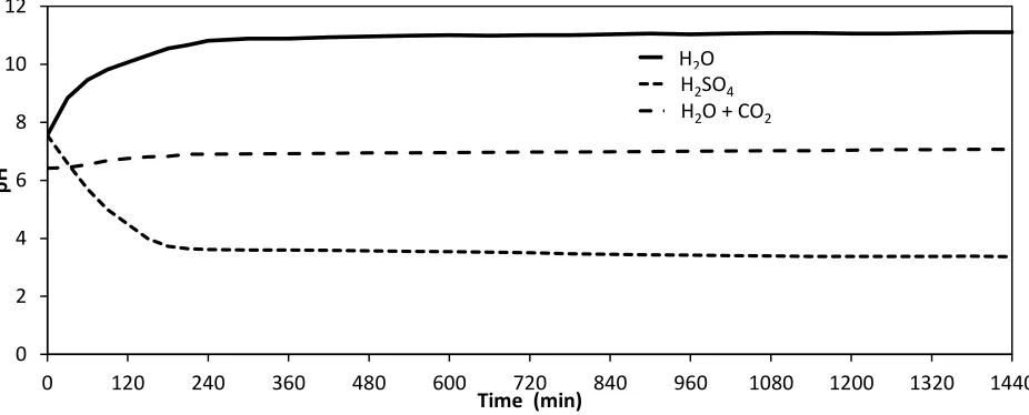
The Nafion® membrane allowed the flow of protons from the anodic compartment into the cathodic compartment. The proton flow rate is driven by the potential between the electrodes and the natural pH of the solutions in the anodic and cathodic compartments. Thus, the pH of the cathodic compartment is influenced by the pH of the anodic solution. Fig. 3 shows the pH value in the cathodic compartment over time for the following anodic solutions: water, water saturated with CO2, and diluted
sulphuric acid. During initial conditions, the current over the electrodes caused primary reactions like the removal of oxygen in the system to occur, however, after about 4 hours these ceased to occur and the pH stabilized. In the case of the diluted sulphuric acid as an anodic solution, more protons were able to flow through the membrane than were consumed by the cathode and, consequently, the pH in the cathodic compartment was lowered. With water as a solution, proton flow was limited and, due to continuous consumption of protons by the cathode, pH in the cathodic compartment rose to 10.5. In the case of the CO2 saturated water in the anodic compartment, a neutral pH in the cathodic compartment
was established by way of CO2 diffusion through the Nafion® membrane. As a consequence, CO2
delivery to the cathodic chamber is limited by the CO2 permeability of the Nafion® membrane. This CO2
transfer over the membrane was measured separately at atmospheric conditions (22 °C and 740 hPa) and is about 0.035 mmol CO2 m-2 s-1, corresponding to a permeability of about 3.8 * 10-10 cm3 (STP) cm
cm−2 s−1 Pa−1. For comparison, in the literature a permeability of 2.69 * 10−11 cm3 (STP) cm cm−2 s−1 Pa−1 at around 50 °C is found [37]. Thus, the presence of CO2 in the cathodic compartment is able to
compensate hydrogen consumption at a nitrate reduction rate of 183 mg m-2 min-1. 0
100 200 300 400 500 600 700 800 900
0 50 100 150 200 250 300
N
itr
ate
+ N
itr
ite
[
m
g L
-1]
[image:8.596.64.541.73.249.2]
Figure 3. pH values in the cathodic compartment over time for the following anodic solutions: H2O;
H2SO4; and water saturated with CO2 (Reaction conditions: specific current of 0.98 A m-2, initial
nitrate concentration 1.2 mmol L-1, Cu and Cu-Pd covered carbon plates).
The buffering effect of the CO2 was also observed in the anodic compartment, where pH was
maintained at 3.5 in the CO2 saturated water. In the case of water as the anodic solution, within the
anodic compartment the pH lowered to a pH of 3 after 4 hours of operation. When diluted H2SO4 was
used as the anodic solution, the pH in the anodic compartment remained constant at a pH of about 2.1.
3.2. Effect of Cathode Catalytic Material on the Removal of Nitrates
Under standard conditions, the reduction potential of the pairs NO3-/N2 0.74 V; NO3-/NO2 0.42
V; NO3-/NO 0.41 V; NO3-/NH4+ 0.36 V were quite similar, which is a result of those reactions occurring
in parallel. Also, hydrogen can be produced under these conditions because the standard reaction potential is also similar. However, the standard reaction potential for the pair NO2-/ N2O has a higher
value of 0.782 V. In addition, the reaction requires two NO3- ions tightly adsorbed to the cathode due to
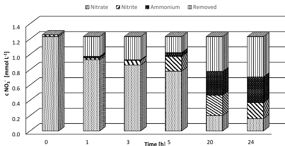
stoichiometry of reaction. When the reaction is first order, this behaviour is less common than for a zero order reaction. While the catalytic cathode also influences which reactions occur favourably, the combination of different catalysts leads to varying nitrate removal, nitrite production, and ammonium production. For example, in Fig. 4, the relationship of nitrate elimination (cinitial=1.2 mmol L-1) with
nitrite and ammonium production over time is shown. In this set-up, water was used as the anodic solution, a copper coated carbon sheet and a second carbon plate with a copper+palladium deposition was used as the catalyst combination, and the specific current applied was 0.98 A m-2. Within the first hour nitrate removal was faster during the period without ammonium and nitrite production. After 5 hours constant nitrite production was parallel to nitrate removal, but after 20 hours, when the nitrates were mostly removed, the nitrite concentration also went down.
0 2 4 6 8 10 12
0 120 240 360 480 600 720 840 960 1080 1200 1320 1440
pH
Time (min)
H20 H2SO4 H2O + CO2 H2O
Figure 4. Pattern of nitrate elimination with an initial concentration of 1.2 mmol L-1. A cathode combination of carbon plate covered with copper and a carbon plate covered with copper+palladium was used. A specific current of 0.98 A m-2 was applied and the anodic solution was water.
[image:10.596.56.518.82.319.2]The results of other electrode combinations under the same reaction conditions are summarized in Table 1. The process performance of the electrode combinations was characterized by a specific nitrate reduction rate, electron balance, and ammonium and nitrite production rate.
Table 1. Effect of the type of electrode on nitrate removal, electron balance, and ammonium and nitrite production with an initial NO3- concentration of 1.2 mmol L-1 and a specific current of 0.98 A
m-2 after 20 hours of operation
Cathode combination
q nitrate removal η electron Ammonium Nitrite
(mg m-2 h-1) (%) (mmol L-1) (mmol L
-1)
CuSn6 100 24 0.237 0.361
CuSn6 / Graphite Cu 99 23.5 0.295 0.360
CuSn6 / Graphite Cu+Pd 222 53 0.349 0.276
Graphite Cu / Graphite Cu+Pd 213 51 0.335 0.210
Results show that nitrite reduction in the system was enhanced when palladium was present. In comparison with only Sn in the first and second arrangement, Pd was more effective in removing nitrites. However, it is unclear why Pd enhanced the nitrate removal rate and reached a better performance in the electron balance because preliminary tests showed that Pd was selective to nitrite and should not have catalysed nitrate removal reactions. Ammonium formation was enhanced when Pd was present, which was also reported by Polatides and Kyriacou [21], but disagrees with the experiments realized by Vooys
0.0 0.2 0.4 0.6 0.8 1.0 1.2 1.4
0 1 3 5 20 24
c NO
3
- [m
m
o
l L
-1]
Time [h]
[image:10.596.88.519.519.638.2]
et al., who reported higher production of byproducts when the Pd-Cu relation was shifted towards Pd [8]. Also of note in relation to the pH of cathodic solution, Ghodbane et al. observed that the formation of byproducts like Ammonia and Nitrite is higher in neutral media [38].
[image:11.596.71.528.218.357.2]3.3. Effect of the Anodic Solution on Nitrate Removal
Table 2. Effect of anodic solution on nitrate removal, nitrite and ammonium formation using different catalyst types and a specific current of 0.98 A m-2 during about 20 hours of operation.
Anolyte H2SO4 H2O H2O+CO2 H2SO4 H2O H2O+CO2 H2SO4 H2O H2O+CO2
q NO3- removal(mg m-2 h-1) q NO2- formation (mg m-2 h-1)
q NH4+ formation (mg m-2 h-1)
Electrode combination [Electron Balance (%)]
CuSn6 135.1
[31.1]
100.1 [24.0]
163.3
[36.0] 0.00 0.52 0.33 0.13 0.29 0.28
CuSn6 / Graphite Cu 104 [24.0]
100.1 [23.5]
128.3
[30.4] - - - -
CuSn6 / Graphite Cu+Pd 199.3 [48.8]
221.7 [53.2]
163.3
[35.5] - - - -
Graphite Cu / Graphite Cu+Pd
286.1 [71.2]
212.9 [51.3]
182.8
[45.5] - - - -
The anolyte influenced the pH of the cathodic compartment and the catalytic reaction was generally enhanced by lower pH. Nitrite formation was completely suppressed using diluted sulphuric acid as an anodic solution. Ammonium formation was also a function of the anodic solution as shown in Table 2 and was lowest when sulfuric acid was used as the anolyte.
The performance of diluted sulphuric acid as the anodic solution was the best when taking into account nitrate removal, nitrite formation, and ammonium formation. A good performance was also obtained using H2O + CO2 as the anodic solution. When water is used as the anodic solution, graphite
plated with Cu+Pd should be used as the catalyst because nitrate removal rate is doubled with this set-up. The importance of the presence of Pd in electrocatalytic nitrate reduction seems to be a key factor in the literature reviewed by Martínez et al. [27].
3.4. Effect of the Specific Current on Nitrate Removal
The reduction potential of nitrate, expressed in units as a voltage on the cathode, specifies a minimum energy for the reduction energy needed to realize the reaction. Thus, a potential value below the reduction potential yields no nitrate reduction. Such conditions were observed with a specific current of 0.8 A m-2 in the laboratory apparatus (water as the anodic solution and CuSn6 as the catalyst). The
Table 3. Effect of specific current on nitrate removal, nitrite and ammonium formation using a CuSn6 catalyst during about 20 hours of operation and using water as the anodic solution.
Current Specific current q NO3- removal q NO2- formation q NH4+ formation
(mA) (A m-2) (mg m
-2 h-1)
[(%)] (mg m
-2 h-1) (mg m-2 h-1)
90 0.80 9 [35] - -
110 0.98 100 [41] 0.53 0.31
130 1.16 163 [52] 0.85 0.14
160 1.43 186 [59] 0.26 0.15
For the pilot plant in batch mode when using water as the anodic solution and running at a higher specific current, the nitrate removal rate was able to be increased even more, but, the electron balance reached a maximum at a specific current of 1.53 A m-2. Under these conditions the nitrate removal rate was 486 mg m-2 h-1 with an electron balance of 71%.
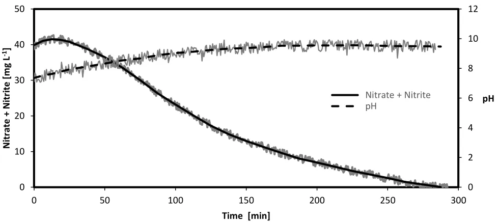
The nitrate removal rate and pH of solution for a sample run with a specific current of 2.55 A m -2 are shown in Fig. 5. During this run, nitrate concentration was measured continuously with a Nitratax
electrode, which is also sensitive for nitrite. This sensitivity allows for increasing concentrations and aware correctness the concentration is specified as the sum of NO3- and NO2-. Within 300 minutes,
nitrates and nitrites were reduced to concentrations close to zero milligrams per litre. The first experiment was expected to show zero-order behaviour for nitrate removal, but, because the Nitratax electrode is also sensitive to nitrite, the more prolonged degradation curve did not remain linear.
Figure 5. Nitrate and nitrite removal in tap water with the pilot apparatus in batch mode (specific current of 1.28 A m-2, CuSn6 cathode, and water as the anodic solution)
0 2 4 6 8 10 12
0 10 20 30 40 50
0 50 100 150 200 250 300
pH
N
itr
ate
+ N
itr
ite
[
m
g L
-1]
Time [min]
[image:12.596.57.547.452.670.2]
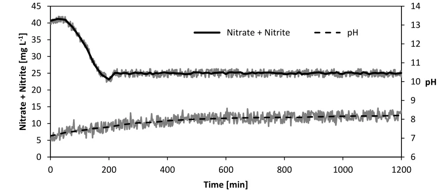
3.5. Continuous Operation of the Pilot Plant
The water extracted from the well was added to the 10 L intermediate tank by opening a solenoid valve; displaced treated water in the system flowed out over a dam. The control of the solenoid valve was governed by software which regulated the nitrate concentration of the circulation water to a limit of 25 mg L-1. A sample in Fig. 6 shows that the controller maintained a nitrate+nitrite concentration at a constant level when applying a specific current of 1.28 A m-2, using a CuSn6 cathode, and water as the
anodic solution. Under these conditions, the nitrite concentration reached 2.8 mg L-1 and ammonium was determined to be 3.2 mg L-1.
Under such reaction conditions, gas samples were taken from the gas phase in the recirculating tank and mass spectroscopy analysis revealed quantitatively that: The N2 to O2 relation was shifted
towards N2; considerable amounts of hydrogen were present; and there was a very small peak for an ion
(mass 44 g mol-1) which may have been either CO
2 or N2O. It is worth mentioning that the presence of
O2 and CO2 in the cathodic chamber is due to the diffusion of these molecules over the Nafion®
membrane.
If the nitrate removal rate is related to the volume occupied in the apparatus, it is possible to compare it to other processes (eg biologic processes) with the intention of benchmarking. While Kapoor and Viraraghavan reported a denitrification rate of 1 to 20 kg NO3- m-3 d-1 in heterotrophic denitrification
processes, using the present pilot denitrification plant the specific reduction rate is 1.2 kg NO3- m-3 d-1.
[image:13.596.68.512.476.669.2]Thus in the electrocatalytic process, the specific nitrate reduction rate is close to the performance of biological systems not taking into account further improvements to the space needed for sandwich electrodes [39].
Figure 6. Nitrate removal in the pilot plant in continuous operation applying a specific current of 1.28 A m-2, using CuSn6 as the catalyst, and water as the anodic solution.
6 7 8 9 10 11 12 13 14
0 5 10 15 20 25 30 35 40 45
0 200 400 600 800 1000 1200
pH
N
itr
ate
+ N
itr
ite
[
m
g L
-1]
Time [min]
3.5. Comparison of cathode materials employed
The cathode material chosen results in an impact on nitrate removal efficiency, formation of by-products, and selectivity towards nitrogen, which has been studied in numerous investigations on catalysts for electro-catalytic nitrate reduction. Table 4 gives an overview of studies realized employing catalysts consisting of one or more elements that were used in our experiment. Most experiments reached nitrate removal rates over 90% when treating an initial nitrate concentration of about 100 mg L-1, thus,
quality standards of 45 mg L-1 recommended by The World Health Organization can be met with the proposed technology. The selectivity towards the production of molecular nitrogen is also of great importance, which is measured indirectly as the difference between the nitrate removal and the nitrite and ammonium concentration. In addition, combinations of metals are characteristically more resistant to corrosion than pure metals [27]. With the exception of Sn the selectivity of metal combinations is higher than the selectivity of pure metals. From the literature it is evident that a cell without membrane separation increases ammonium oxidation on the anode. However, nitrite oxidation on the anode is impossible when using a membrane, which leads to a higher electron efficiency because the nitrate/nitrite pair cannot act as carrier of charges [27]. The second column in Table 4 reveals additional information about the experimental setup such as initial concentration, electrolyte composition, pH etc. It is worth mentioning that by injecting CO2 into the anodic compartment to stabilize pH, this study is able to
[image:14.596.55.545.448.754.2]produce potable water without subsequent steps to reach a neutral state as required by drinking water standards. Such a strategy has not yet been reported for electro catalytic nitrate reduction processes.
Table 4. Summary of electro-catalytic nitrate reduction of different types of cathodes.
Catalyst Reaction conditions Membrane Separation q NO3
removal N2selectivity η electron Reference
Cu/Sn cNO3
-,initial 75 mg L-1,
CO2 buffer Nafion 99% 81% 24%-36%
Present study
Pd/Cu cNO3
-,initial 75 mg L-1,
CO2 buffer Nafion 90% 78% 45%-70%
Present study
Pd/Cu cNO3
-,initial 48 mg L-1, pH
uncontrolled No 99% 50% [26]
Pd/Cu cNO3
-,initial 3100 mg L-1,
CO2 buffer Nafion 99% 64% [40]
Pd/Sn cNO3
-,initial 100 mg L-1,
neutral pH Nafion 99% 85% [41]
Pd cNO3
-,initial 3100 mg L-1,
pH uncontrolled No 29% 1% [21]
Cu cNO3
-,initial 3100 mg L-1 ,
Cu deposit on Pt, pH 7 Nafion 99% 64% [40]
Cu pH 12, relation surface area
Cu/Bi 100 mg L
-1 initial, neutral
pH No 88% 60% 30%-70% [36]
Cu/Sn 1000 mg initial; pH
uncontrolled Diaphragm 30% 25% 30% [43]
Cu/Zn cNO3
-,initial 37 mg L-1,
pH 7.85, NaCl added No 94% [44]
Cu/Zn cNO3
-,initial 37 mg L-1, pH
uncontrolled, NaCl added No 99%
99%
[45]
CuZnOx cNO3
-,initial 37 mg L-1,
pH uncontrolled
Ultrex
CMI-7000 92% 60% [46]
Cu/Zn cNO3
-,initial 100 mg L-1,
pH uncontrolled, No 90% 30% [47]
Cu/Zn cNO3
-,initial 3100 mg L-1,
pH uncontrolled
Divided Undivided
99% 91%
3%
62.3% [21]
Sn cNO3
-,initial 3100 mg L-1,
pH uncontrolled Nafion 99% 92% 22%-60% [48]
4. CONCLUSIONS
The results obtained in the laboratory and pilot scale operation show complete nitrate removal in potable water and consequently may offer an alternative treatment to common methods used, like ion exchange or reverse osmosis. The production of nitrite and ammonium must be further reduced, which may restrict the use of this method in potable water production. However, applications in water treatment for aquaculture or wastewater generated by the mining industry could require such treatments. It is worth mentioning that reverse osmosis produces concentrated reject water, which can be treated by the electro-catalytic process as well.
The graphite electrodes coated with copper and palladium showed the best performance with respect to the specific nitrate removal rate and a lower production of nitrite and ammonium. However, due to the high cost of the noble metal palladium, authors classify the CuSn6 cathode as the more cost efficient catalyst.
A high electron balance of more than 70% was obtained by operating the pilot plant with a specific current near 1.5 A m-2. An increase of specific current led to a higher production of nitrites and consequently established a limit for operation.
The best performance was obtained with the diluted sulfuric acid (c=0.01 mol L-1) as the anodic solution and may be the most energy efficient because of its low conductivity. A feasible alternative is the use of a solution of saturated carbonic acid. One advantage is that this solution does not impact the pH in the cathodic compartment.
THE AUTHORS HAVE DECLARED NO CONFLICT OF INTEREST
References
1. A. Chávez, C. Maya, J. Durán, A. Becerril, R. Gibson, B. Jiménez, Environ. Poll., 159 (2011) 1354.
2. L.A. DeSimone, P.A. Hamilton, R.J, The Quality of Our Nation’s Waters - Quality of Water from Domestic Wells in Principal Aquifers of the United States, 1991–2004. U.S. Geological Survey Circular 1332, (2009) USA.
3. Nitrates Directive 91/676/EEC, REPORT FROM THE COMMISSION TO THE COUNCIL AND THE EUROPEAN PARLIAMENT on the implementation of Council Directive 91/676/EEC concerning the protection of waters against pollution caused by nitrates from agricultural sources based on Member State reports for the period 2008–2011, (2013) Brussels, Belgium.
4. N. Barrabés, J. Sá, Catalytic nitrate removal from water, past, present and future perspectives, Appl. Catal.Part B: Environ., 104 (2011) 1.
5. K.D. Vorlop, T. Tacke, Chem. Ing. Tech., 61 (1989) 836.
6. E.A. Stadlbauer, H. Löhr, J. Eberheim, B. Weber, Verfahren zur reduktiven Eliminierung von Nitrat aus flüssigen Medien. German Patent DE 19512955A1, (1996).
7. J.F.E. Gootzen, P.G.J.M. Peeters, J.M.B. Dukers, L. Lefferts, W. Visscher, J.A.R. van Veen, J. Electroanal. Chem., 434 (1997) 171.
8. A.C.A. de Vooys, R.A. van Santen, J.A.R. van Veen, J. Mol. Catal. Part A: Chem., 154 (2000) 203.
9. J.W. Peel, K.J. Reddy, B.P. Sullivan, J.M. Bowen, Wat. Res., 37 (2003) 2512. 10. G. Horanyi, E.M. Rizmayer, J. Electroanal. Chem., 188 (1985) 265.
11. H.L. Li, J. Electrochemical Reduction of Nitrate and Nitrite in Concentrated Sodium Hydroxide at Platinum and Nickel Electrodes, Electrochem. Soc., 135 (1988) 1154.
12. L. Ma, B.Y. Zhang, H.L. Li, J.Q. Chambers, J. Electroanal. Chem., 362 (1993) 201. 13. J.D. Genders, D. Hartsough, D.T. Hobbs, J. Appl. Electrochem., 26 (1996) 1.
14. C. Milhano, D. Pletcher, The Electrochemistry and Electrochemical Technology of Nitrate. In: Ralph E. White (Hg.): Modern Aspects of Electrochemistry, No. 45. New York, NY: Springer-Verlag New York, 2009.
15. D. Pletcher, Z. Poorabedi, Electrochim. Acta, 24 (1979) 1253.
16. G.E. Dima, A.C.A. de Vooys M.T.M. Koper, J. Electroanal. Chem., 554 (2003) 15.
17. T.T.P. Nguyen, B.K.D. Do, N.N. Bui, M.A. Pham, T.V. Nguyen, ECS Transactions, 53 (2013) 41. 18. E. de Dibyendu, D. James, E.E. Kalu, Cyclic Voltammetric Studies of Nitrate and Nitrite Ion
Reduction at the Surface of Iridium-Modified Carbon Fiber Electrode, J. Electrochem. Soc., 147 (2000) 4224.
19. J.F.E. Gootzen, L. Lefferts, J.A.R. van Veen, Appl. Catal. Part A: Gen., 188 (1999) 127. 20. O. Brylev, M. Sarrazin, L. Roué, D. Bélanger, Electrochim. Acta, 52 (2007) 6237. 21. C. Polatides, G. Kyriacou, J. Appl. Electrochem., 35 (2005) 421.
22. J.C. Fanning, Coord. Chem. Rev., 199 (2000) 159.
23. A.M. Berquist, J.K. Choe, T.J. Strathmann, C.J. Werth, Wat. Res., 96 (2016) 177. 24. A. Boley,W.R. Müller, G. Haider, Aquacultural Eng., 22 (2000) 75.
25. S.A. Castine, A.D. McKinnon, N.A. Paul, L.A. Trott, R. de Nys, Aquacult. Environ. Interact., 4 (2013) 285.
26. J.F. Su, I. Ruzybayev, I. Shah, C.P. Huang, Applied Catalysis B: Environ. 180 (2016) 199. 27. J. Martínez, A. Ortiz, I. Ortiz, Applied Catalysis B: Environ. 207 (2017) 42.
29. S. Garcia-Segura, M. Lanzarini-Lopes, K. Hristovski, P. Westerhoff, Applied Catalysis B: Environ. 236 (2018) 546.
30. Z. Zhang,Y. Xu, W. Shi, W. Wang, R. Zhang, X. Bao, Chem. Eng. J., 290 (2016) 201. 31. K. Lüdtke, K.V. Peinemann, V. Kasche, R.D. Behling, J. Membr. Sci., 151 (1998) 3. 32. M. Pera-Titus, M. Fridmann, N. Guilhaume, K. Fiaty, J. Membr. Sci., 401 (2001) 204. 33. M.A. Hasnat, M.A. Islam, M.A. Rashed, RSC Adv., 13 (2015) 9912.
34. K. Bouzek, M. Paidar A. Sadílková H. Bergmann, J. Appl. Electrochem., 31 (2001), 1185. 35. B.P. Dash, S. Chaudhari, Wat. Res., 39 (2005) 4065.
36. W. Gao, L. Gao, D. Li, K. Huang, L. Cui, J. Meng, J. Liang, J. Electroanal. Chem., 817 (2018) 202.
37. S. Ma, E. Skou, Solid State Ionics, 178 (2007) 615.
38. O. Ghodbane, M. Sarrazin, L. Roú, D. B´ılanger, J. Electrochem. Soc., 155 (2008) 117. 39. A. Kapoor, T. Viraraghavan, J. Environ. Eng., 123 (1997) 371.
40. M.A. Hasnat, S. Ben Aoun, S.M. Nizam Uddin, M.M. Alam, P.P. Koay, S. Amertharaj, M.A. Rashed, M. M. Rahman, N. Mohamed, Appl. Catal. Part A: Gen., 478 (2014) 259.
41. Y. Wang, J. Qua, R. Wu, P. Lei, Wat. Res., 40 (2006) 1224. 42. D. Reyter, D. Bélanger, L. Roué, Wat. Res., 44 (2010) 1918.
43. Z. Mácová, K. Bouzek, J. Šerák, J. Appl. Electrochem., 37 (2007) 557. 44. N. Fan, Z. Li, L. Zhao, N. Wu, T. Zhou, Chem. Eng. J., 214 (2013) 83.
45. M. Li, C. Feng, Z. Zhang, Z. Shen, N. Sugiura, Electrochem., 11 (2009) 1853. 46. S. Yang, L. Wang, X. Jiao, P. Li, Int. J. Electrochem. Sci., 12 (2017) 4370.
47. M. Li, C. Feng, Z. Zhang, X. Lei, R. Chen, Y. Yang, N. Sugiura, J. Hazard. Mat., 171 (2009) 724 48. I. Katsounaros, D. Ipsakis, C. Polatides, G. Kyriacou, Electrochim. Acta, 52 (2006) 1329.