Rochester Institute of Technology
RIT Scholar Works
Theses
Thesis/Dissertation Collections
11-21-1997
The Design of a multiple position turret for
changing robot end effectors
William Lang
Follow this and additional works at:
http://scholarworks.rit.edu/theses
This Thesis is brought to you for free and open access by the Thesis/Dissertation Collections at RIT Scholar Works. It has been accepted for inclusion
in Theses by an authorized administrator of RIT Scholar Works. For more information, please contact
Recommended Citation
THE DESIGN OF A MULTIPLE POSITION TURRET FOR
CHANGING ROBOT END EFFECTORS
by
William H. Lang
t
A Thesis Submitted
In
Partial Fulfillment
of the
Requirements for the
MASTER OF SCIENCE
In
Mechanical Engineering
Thesis Advisor
Dr. Michael Hennessey
_
Mr. Tim Spencer
_
Mechanical Engineer / Kodak
Dr. Charles Haines
_
DEPARTMENT OF MECHANICAL ENGINEERING
COLLEGE OF ENGINEERING
ROCHESTER INSTITUTE OF TECHNOLOGY
NOVEMBER 21,1997
The Design of a Multiple Position Turret for Changing Robot End
Effectors
I,
William H. Lang, hereby deny permission to the Wallace Library of the
Rochester Institute of Technology to reproduce my thesis in whole or in part.
TABLE
OF
CONTENTS
?
ABSTRACT.
CHAPTER I.
INTRODUCTION
1
CHAPTER II.
WHAT
MAKES THIS
DESIGN
DIFFERENT?
6
CHAPTER HI.
TURRET'S
PRELIMINARY DESIGN
7
CHAPTER IV.
TURRET'S
STRUCTURE
9
CHAPTER
V.
TURRET
DESIGN FEATURES
11
CHAPTER VI.
HARMONIC DRIVE TRANSMISSION
15
CHAPTER
VII. REPEATABILITY,
BACKLASH,
&
LIFE
19
CHAPTER VIII.
TURRET
HEAD INTERIA
26
CHAPTER
IX.
TURRET MOTION CONTROL
30
CHAPTER
X.
TURRET TESTING
37
CHAPTER
XI.
RECOMMENDATIONS
&
CONCLUSIONS
39
?
REFERENCES
44
?
ACKNOWLEDGEMENTS
45
APPENDIX
A:
TURRET
SPECIFICATIONS46
APPENDIX
C:
WIRING DIAGRAMS
50
APPENDIX D:
MOTION
ARCHITECT
PROGRAMS
52
APPENDIX E:
TURRET PART
DRAWINGS
53
APPENDIX F:
VENDOR PRODUCT INFORMATION
54
?>
ABSTRACT
?>This
paperdiscusses
the
design
andbuild
of a multiple positionturret
usedto
simultaneously
attach six end effectorsto
afour-degree
offreedom Adept
robot.The
main objective of
this
thesis
is
to
develop
a prototypetool
changerthat
is
different,
more cost
effective,
and offers morefeatures
andversatility
than
any
other.Use
ofthe turret
allowsthe
robotto
quickly
changethe
end effectorin
useby
simply
rotating
any
ofthe
othersinto
the
ready
position.This
reducesthe tool
changing
time
in
ahigh-speed
assembly
processthat
is
normally
associated with conventionaltool
changers
disconnecting
one end effector andpicking up
another.Employing
the turret
concept
in
a roboticassembly
operation will alsolengthen
the
life
ofthe
robotbecause
there
arefewer
movesthat
have
to
be
madeby
the
robotitself.
The
turret
is
approximately 8
inches
high,
7
inches
wide andits
turntable
is 6.25
inches
in
diameter.
This
small envelopeis
alarge
benefit
overthe
bulky
systemthat
wouldbe
needed
for
the
moretraditional
tool changers.The
turret's
weight while populated withsix small end effectors
is
approximately
10.5
pounds.The
cost ofthe
turret,
notCHAPTER
I.
INTRODUCTION
Turret
tool changershave been designed
in
the
field but
there
arefew
pre-designedturrets
andturret
accessoriesthat
canbe
purchasedfrom
a manufacturer or roboticcomponent
distributor.
The
initial
cost ofaturret tool
changertends to
be higher
thanthe
more conventionaltypes
oftool
changers,
whichdeters
companiesfrom
purchasing
such equipment.
Some
turret tool
changers andturret
head
accessoriesthat
have
been
designed
andsoldby
various companiesin
the
past are mentionedbelow.
?
Robohand
is
acompany in
Monroe,
CT
that
designs
and manufactures pneumaticgrippers,
powerslides,
linear
thrusters, feed
escapements,
rotary
actuators,
and muchmore
[5].
They
are one ofthe
most popular companiesin
the
field
of off-the-shelfassembly
and automation components.Robohand,
like
many
othercompanies,
accommodate
their
customer's application needsby
altering
their
current product ordesigning
specialautomation equipmentthat
is
notnormally
stocked.A
turret tool
changeris
not one ofRobohand's normally
stockeditems,
however,
they
designed
oneturret tool
changerfor
a customer(see Figure
1).
This
turret
has
aharmonic drive
transmission that
is
in
line
with aDC
servomotor.It
has
six endeffector
stations,
all of whichhave
a platformthat
an end effector wouldfasten
to.
There is
a small pneumatic cylinderthat
is
attachedto the
platformthat
pivotsthe
endeffector 90 with respect
to the turret
head.
This
would allowthe
userto
pick a partin
one
direction (Y-axis travel),
pivotthe
platform90,
and placethe
part normalto the
pick
direction (X-axis travel)
withoutrotating
the turret
head
during
this
operation.Through
avery
clever pneumaticslip ring
design,
the
otherfive
end effectorshave
pressure maintainedto
allowholding
a part whileindexing.
'
'
~i
litJte
I;'.';:'''
S
*M^-S
?
Mack Corporation is
a
company in
Flagstaff,
Arizona
that
manufactures
off-the-shelf robotic
components
that
aredesigned
to
be
usedin
fluid
power ornon-servo applications
[6].
They
offer a productline
ofgrippers,
rotary
actuators,
slides,
pistons,
turret
heads,
and other
fluid
poweraccessories.
These
accessories canbe joined
together to
build
the
"non-servo
robot" whichif
designed
and assembledproperly
will performmany
different
combinations ofroll, pitch,
and yaw.Figure
1:
Robohand Turret
Tool
Changer
[5]
There
aremany
manufacturersthat
offer robotic accessories such asRobohand, Bimba,
[image:8.551.75.487.144.481.2]heads.
They
canbe
purchasedin
three
different
end effectormounting
configurations(see Figure 2).
The
axialturret
heads
allowthe
userto
mount2, 4,
or6
end effectorsparallel with
the
line
ofrotation.Radial
turret
heads
allowthe
userto
mount2, 4,
or6
end effectors perpendicular
to the
line
ofrotation.Lastly,
the
45 cantedturret
head,
which
is
the
style ofthe turret
head in
this
thesis,
allowsthe
userto
mount2, 4,
or6
end effectors 45
to the
line
of rotation.All
three
configurationshave
their ownadvantages
depending
onthe
layout
ofthe
assembly
process.The
designer
whoincorporates
aMack
turret
head into his
orher
tool
changer wouldsupply
their own*
f
.K<^\
.11',
l-Ynf^
f'l-''-V-'T"'-}-"
t
[i
i.._.Jj_-L .:.___-*..vSj-:;.,;?;
X;
,,- i->.
-->;_---AXIAL TURRET
RADIAL
45CANTED
HEAD
TURRET HEA1)
TURRET HEAD
Figure
2: Mack Corporation
-Available Turret Heads
means of rotational power and air
supply
to the turret.
These
turret
heads
areoff-the-shelf
items
that
canbe
purchasedatany
time.
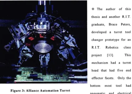
?
Alliance
Automation
ofRochester,
New York
is
a worldwideinnovator in
the
field
of customized
turn-key
flexible
automation systems[4].
They
designed
a modularprinted circuit
board
insertion
cell called Boardmatethat
handles
both
through-hole
and surface mount components.
Their primary
sources ofpick and place motions camefrom
ahigh
speedSCARA
robot and aturret tool
changerthat
is
populated with eight [image:9.551.68.470.310.420.2]not
have
any
trouble
utilizing
all eight end effectorsfor
different
gripperfinger
geometries
(see Figure
3).
The
processesfor
pneumatic and electrical actuation ofthe
end effectors are unknown.
This
turret tool
changer came withthe
modular automatedassembly cell,
which stores anddispenses
the
parts.It is
possiblethat the
actualturret
head itself
may
be designed
and purchasedthrough
Alliance, however,
it is
not anormally
stocked,
off-the-shelfitem
that
canbe
purchased atany
time.
?
The
author ofthis
thesis
and anotherR.I.T.
graduate,
Brace
Peters,
developed
aturret
tool
changer prototype
for
anR.I.T.
Robotics
classproject
[13].
This
mechanism
had
aturret
head
that
had
five
endeffector
facets.
Only
the
bottom
most toolhad
pneumatic and electrical
PI
I
1
!1 R^
^ypiB
Figure
3:
Alliance
Automation Turret
capabilities.
There
was a pneumatic cylinderthat
engagedtwo
positive pressure airports
(solenoid
actuated)
andthree
electrical contactsfor
end effector sensorfeedback.
A
24VDC
servomotor poweredthis mechanism,
which wasdirectly
in line
with a5
position
Geneva
wheel.The
idea
of aGeneva
wheel asthe
indexing
transmission
is
[image:10.551.65.493.236.542.2]with
the
imprecise
machining
ofthe
individual
parts.This
prototypedemonstrated
the
feasibility
of aturret
tool
changerin
anassembly
production environment.This
prototype resides at
the
R.I.T.
Robotics lab for
usein
future
projects.It has
been
observedin
the
pastthat
othercompanies,
such asthose
mentionedabove,
have developed
their
ownturret tool
changersfor
assembly
uses wherefrequent
toolchanges are necessary.
The
whole concept ofusing
aturret
asthe
meansfor
changing
end effectors
is
a goodidea.
It
is
atime
andmoney
saverdue
to
higher
machineefficiencies and greater production rates.
Some
companiesmay
realizethat the
initial
cost ofa
fully
poweredturret tool
changeris
more expensivethan
more conventionaltool
changers,
however,
over a short period oftime,
it
willpay
for
itself
withthe
higher
CHAPTER
II.
WHAT MAKES THIS
DESIGN DIFFERENT?
This
turret
has
afew
ofthe
same characteristics asthe
above-mentionedturrets,
however,
some ofthe
addedfeatures
makeit
quitedifferent.
Each
end effectorhas
pneumatic
supply
and electricalfeedback lines
plumbedto
them,
which are externalto
the
turret
head.
This
feature
givesthe
userthe
capability
ofpowering
(actuating)
eachof
its
six end effectors atany
time,
atany position,
and all at onceif
needed.It
alsoprovides
the
ability
to
pick and place at almostany
angleif necessary
for
the
moreintricate
partinsertion
operations.With
the
pneumatic and electricalinput
connectionsbeing
independent
ofthe turret's
motion orposition, the turret
is
also capable ofactuating any
end effector whileperforming
aturret
rotation move.Having
the
ability
to
pickup
andhold
sixdifferent
parts at oncebefore
moving
to the
destination
positionis
also atime
saver.This
turret,
whichin
some waysis
very
similarto
Robohand's
design,
has
aharmonic
drive
transmission
that,
when coupled withthe
DC
servomotor androtary
encoder,
its
movement
is
very
accurate and repeatable withvirtually
nobacklash.
This
control ofrotational movement
is
imperative in high
speed andhigh
precision partinsertion
andassembly
operations.Due
to the
high
reduction ratio ofthe
harmonic drive
gear set(50:1),
the turret
has
ahigh
outputtorque
rating.The
three-phase
DC
servomotorcoupled with
this
transmission makesit
capable of rapid rotation movements withhigh
CHAPTER III.
TURRET'S
PRELIMINARY
DESIGN
There
weremany
constraints and guidelinesin
the
design
ofthe turret.
The
turret
as asystem must
have
all ofthe
features
and qualitiesthat
makeit
unique,
highly
efficient,
and
different
from
otherturrets.
Some
ofthe
design
criteria takeninto
considerationare user
interface,
weight,
speed,
aesthetics,
easy
tool
changeover,
precise motioncontrol, repeatability, accuracy,
backlash,
and mostimportantly,
a ruggeddesign.
The
turret's
indexing
speed mustbe
greaterthan that
ofthe
more conventionaltool
changers which could
take
up
to
2-4
secondsdepending
onthe
speed ofthe
robot andthe
hand
exchange unit[5].
The
turret
is
designed
to
index
to the
desired
end effectorin
the time
it
takes
the
robotto
reachthe
next programmeddestination.
This
is
the
ideal
situation wherethere
is
no stalltime
in between
the
robot's tooldestinations.
Weight
and size considerationsplay
abig
rolein
the
design
ofthe
turret.This
turretwill
be
used on anAdept-1
robot,
whichhas
a maximum payload of25
Lbs.
It
is
advantageous
to
keep
the
weightto
a minimumto
allowfor higher
attainable robotspeedswithout
failure
or unwantedfatigue.
Since
the turret
may
be
usedin many different
setups, the
userinterface
mustbe
takeninto
consideration.It
mustbe
easy for
the
userto
changethe
tools that
fasten
to the
The best design is
adesign
that
has
very
little
to
nobacklash in
the
system,
is
highly
repeatable,
andhas
great positional accuracy.The
mechanism mustbe
rugged andshould
have high life
expectancy.The
turret
shouldbe
ableto
withstand afactory
production environment
that
is
capable ofoperating reliably for
three
full
shifts aday
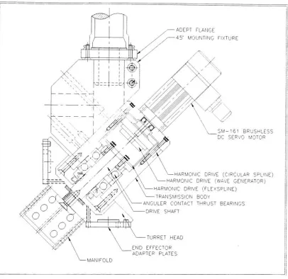
CHAPTER
IV.
TURRET'S STRUCTURE
The
turret
as a wholeis
attached with a 45 adapterblock
to the
flange
that
is
onthe
end of
the
robot's quill(see Figure
4).
The
body
ofthe
turret,
whichis fastened
to the
45
mounting
fixture,
houses
the
in-line harmonic drive
transmission.
The
output shaft
of a
three-phase
DC
servomotordirectly
powersthe
transmission's
input.
The
outputside of
the
harmonic drive
transmission
is fastened
to the
maindrive
shaftthat
is
supported on
two
heavy-duty
angular contactthrust
bearings.
The
heavy-duty
bearings,
which contribute
to the
ruggedness ofthe
design,
are preloadedtogether
with alock
nutand
lock
washer.The drive
shaft and motor shaft are sealed withChicago Rawhide
oil sealsbecause
the
harmonic drive
transmission
must operatein
a volume oflubricating
oil.The
body
ofthe turret
andthe
axes of allrotating
elements are canted 45from
the
robot's quillz-axis.
The
turret
head is keyed
andrigidly
fastened
to the
outputdrive
shaft.With
eachend effector
being
45from
the turret
head's
axis ofrotation,
it has
a configurationsimilar
to that
found
on someNC
turret
drilling
machines.Since
weightis
afactor in
this
design,
materials were selectedcarefully,
notto
over-weigh
the
system.In
an effortto
keep
the
weightto
aminimum,
the turret's
45adapter
plate,
body,
andhead,
which makeup
the
turret's
mainstructure,
weremachined
from
magnesium.The
density
of magnesiumis
approximately 65
percent ofaluminum while still
keeping
sufficient structuralintegrity
as aluminum would.This
ADEPT FLANGE
MOUNTING FIXTURE
SM-161 BRUSHLESS DC SERVO MOTOR
HARMONIC DRIVE (CIRCULAR
SPLINE)
HARMONIC DRIVE (WAVEGENERATOR)
HARMONIC DRIVE
(FLEXSPLINE)
TRANSMISSION BODY
ANGULER CONTACT THRUST BEARINGS
DRIVE SHAFT
TURRET HEAD
END EFFECTOR ADAPTER PLATES
-MANIFOLD
Figure
4: Turret Tool
Changer
Assembly
[image:16.551.75.481.124.518.2]CHAPTER
V.
TURRET
DESIGN
FEATURES
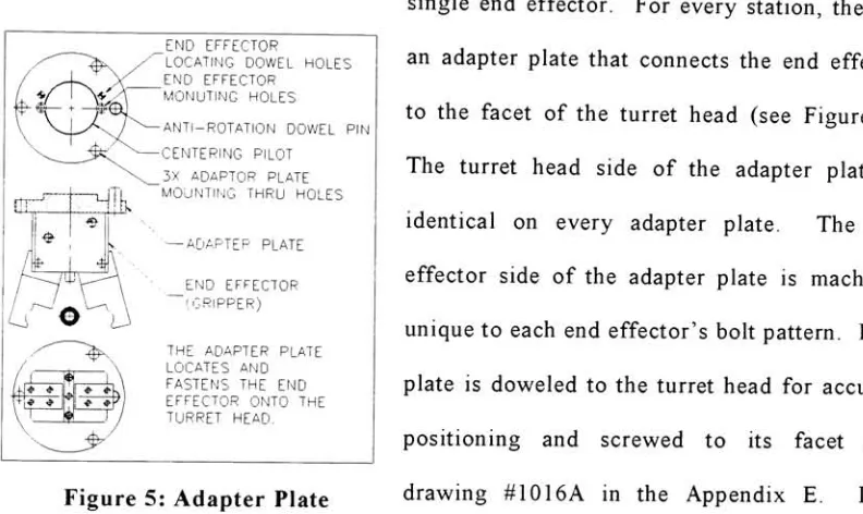
The
turret
head is
capable ofholding
six small endeffectors onmounting facets
that
arepositioned 60 apart
from
one another.Each facet
provides amounting location
for
asingle end effector.
For every station,
there
is
an adapter plate
that
connectsthe
end effectorto the
facet
ofthe turret
head (see Figure
5).
The
turret
head
side ofthe
adapter plateis
identical
onevery
adapter plate.The
endeffector side of
the
adapter plateis
machinedunique
to
each end effector'sbolt
pattern.Each
plate
is doweled
to the turret
head
for
accuratepositioning
and screwedto
its
facet
(see
Figure
5:
Adapter
Plate
drawing
#1016A
in
the
Appendix
E.
It
is
intended
for
the
user withmany
setupsto
keep
the
end effector attachedto the
adapterplate at all
times
even whenit is
not attachedto the turret.
This
will ensurethat
whenrefastened
to the turret
head
in
future
setups, the
end effectoris
positionedexactly
the
same as
previously
usedin
past setups. END EFFECTORLOCATING DOWEL HOLES END EFFECTOR
'MONUTING
HOLESANTI-ROTATION DOWEL PIN
CENTERING PILOT
3X ADAPTOR PLATE MOUNTING THRU HOLES
ADAPTER PLATE
EFFECTOR !,GRIPPER)
THE ADAPTER PLATE LOCATES AND FASTENS THE END EFFECTOR ONTO THE TURRET HEAD.
The
end effectordisks
are positioned onthe
turret
head
in
such away
that
the
centerline of
the
bottom
most end effectoris in line
withthe
robot's z-axis.This
feature
allowsthe
userto
rotatethe
end effector aboutthe
robot's z-axisby
rotating
the
[image:17.551.74.470.195.431.2]A
three-phase
DC
servomotor manufacturedby
Compumotor
[3]
providesthe
powerfor
the turret.
A
built-in
hall-effect
encoder monitors motor positionfeedback
to the
controller.
The DC
servomotorhas
a maximum rated speed of7,500
RPM.
With
use ofa
50:1
harmonic drive
gearreducer,
output speeds ofup
to
2.5 RPM
canbe
achieved.The
controllerthat
was purchased withthe
servomotoris
equippedwith10
outputs and18
inputs.
These inputs
and outputs are usedto
create a closedloop
systembetween
the
controller and
the
servomotor as well asto
communicate withthe
robot's controller.The
outputs canbe
usedto
actuatethe
solenoidsfor
end effector actuationif
wiredproperly.
They
can alsobe
usedto
send signalsto the
robot controller.The inputs
canreceive signals
from
sensors orfrom
the
robot controller.Pneumatic
and electricalplumbing
arebrought
to the turret
head
from
the
pneumaticsolenoids and
the
controller's signal communicationterminal
respectively.The
lines
are plumbed
down
throughthe
robot'shollow
z-axisquill,
throughthe
45 adapterblock,
andinto
a manifoldthat
is fastened
to
the
outside center ofthe
rotating
turret
head.
The
manifoldtransfers
the
hard
plumbing
to
quickdisconnect
push-typepneumatic
fittings
and9-pin
D-sub
electrical connectors.The
pneumatic connections ateach
mounting facet
consist oftwo
positive pressure portsfor
a one ortwo-way
endeffector actuation and one negative pressure port
for
vacuum pickup
whileusing
anexternal vacuum generator.
The
pneumatic and electrical connections are provided ateach
mounting location allowing
all six end effectorsto
be
operational at alltimes
andThe
turret
head
is
equipped with ahoming
sensorthat
communicates withthe
controller,
establishing
a reference position uponpowering
the
system.An inductive
proximity
switchis
attachedto the
body
ofthe
turret
which senses an1/8"
diameter
dowel
pinthat
is
pressedinto
the
back
side ofthe turret
head.
The
homing
operationis
a sequence ofmoves
that
positionthe
axis ofthe turret
head
using
the
home limit input
channel
in
the
controller.As
the
homing
operationis
complete,
the
encoder countis
setto zero,
which establishes a zero reference position.Since
there
is
plumbing
channeledto the
center ofthe turret
head,
it
is
essentialthat the
head does
notturn too
far in
eitherdirection
which would causethis
electrical andpneumatic
plumbing
to twist
andfatigue.
To
avoidthis
from
happening,
there
areclockwise and counter-clockwise ends of
travel
limit
switchesincorporated into
the
system.
The
clockwise(CW)
and counter-clockwise(CCW)
limit
switches arefastened
to the
body
ofthe turret
along
with a slideblock
that triggers the
sensors.This
slidehas
a pin pressedin
it
that
follows
a spiral groovethat
is
machinedinto
the
back
side ofthe turret
head.
The
spiral slotis illustrated
in
the turret
head
partdrawing
(#3003C)
in
Appendix
E.
In
this
case, the turret
is only
allowedto travel
a maximum of 720between
end-of-travellimits.
This
720rotation
capability
makeit
possiblefor
the
turret to
pick and placefrom any
position possible without excessivetwisting
ofthe
plumbed electrical or pneumatic
lines.
If
an end-of-travellimit
is triggered,
the turret
head rapidly
decelerates
to
astop
andcontroller must
be defined
suchthat
the turret's
location does
notstep
outsidethe
end-of-travel
limits.
A start-up
programinitiates
ahoming
sequence ofthe turret
head
at a slow rotationalvelocity
in
the
CW direction.
If
the
CW
end-of-travellimit
switchis
encountered priorto
sensing
the
homing
pin,
the turret
will changedirections
and continuein
the
oppositedirection
to
searchfor
the
home
position.If
the
CCW
end-of-travellimit is
triggered
before
the
homing
pinis
found,
the
motorwill shutdown
atthis
location.
The
turret
has
six end effectors attached andready
for
use.They
consist of2 SMC
(#ZHI07B)
venturi-type vacuum generatorsfor
a suction pick andplace, three
2-jaw
parallel
grippers,
and one3-jaw
centering
gripper.The SMC
(#MHQ2-10C)
2-jaw
spring
loaded
parallel gripperis
equipped with aHall-effect
sensorthat
detects
the
gripper
in
the
open positionby detecting
a magnetthat
is
pressedin
the
end ofthe
gripper's piston.
This
sensorhas
two
wiresthat
canbe
connectedto
the
9-pin
D-sub
connector
to
be
usedin
one ofthe
controller'sinputs
in
a closedloop
system.The
SMC
(#MHR3-10R)
3-jaw centering
gripperis
normally
usedfor
round partsthat
arein
need of
centering
before
placing.The
othertwo
2-jaw
parallel grippers areSchunk
CHAPTER VI.
HARMONIC DRIVE
TRANSMISSION
The
authorbelieves
that the
harmonic drive
mechanical powertransmission
is
a uniquefeature
ofthis
design,
not usedin
similartooling.
This
type
ofdrive has
advantagessuch as
high
gear reduction ratiosin
a single stagesystem,
very
low
backlash,
andin
line
input/output
that
cannotbe
equaledby
conventional geartransmissions.
The
harmonic drive
principleis
a puretorque
couple with all concentric elements and putsextremely
high
reduction ratio capabilitiesinto
avery
compact andlightweight
package.
The
precision and performance ofharmonic
drive
gearing
areideal
in
applications
requiring
accuratepositioning
orprecise motioncontrol.Harmonic
drive
transmissions
providethe
high
rotational and positionalaccuracy
required of precision
drive
mechanisms and control systems essentialin
today's
advanced
industrial
robots.Harmonic
drive
transmissionshave been widely
utilizedin
multi-jointed electro-mechanical and
hydro-mechanical
robotsto
rotatethe
body,
raiseand
lower
the arms,
bend
the elbows,
and rotatethe
wrists.Precision
and compactharmonic
drive
actuatorsfind
wide usesin
optical spectrumanalyzers,
and othermeasuring instruments
providing
micro-motion control.Harmonic drive
transmissions consist ofthree
different
elements: a circularspline,
aflexspline,
andawave generator(see Figure 6).
There
aremany different
combinationsof
implementing
thesethree
elementsin
a transmissionassembly
to
accomplishThe
circular splineis
around,
,, . . ... ... . .
Flexspline
thick-walled,
rigidring
withAnellptcal
fionrigto',
internal splineteeth.
It normally
externalqea
functions
asthe
fixed
or non-Circular Spline
Around,
rigicj,
rotating
memberbut it
canbe
usedirternal9ear
as a
rotating
output element as wellWave Generator
~-An,
e^iovcaiin
certain speedincrease
ball bear ng assembly
applications.
Figure
6:
Harmonic
drive
components[1]
The
flexspline has
externalteeth
andis
aflexible
ornon-rigid,
thin-walled,
cylindricalcup
whichis
smallerin
circumference andhas
two
less
teeth than the
circular spline.It
is
normally
the
rotating
output elementbut
canbe
utilized asthe
fixed,
non-rotating
memberwhen output
is
through the
circular spline.The
wave generatoris
an elliptical cam enclosedin
an anti-frictionball
bearing
assembly.
It
normally
functions
asthe
rotating
input
element.The
wave generatoris
inserted into
the
bore
ofthe
flexspline
andit
then
forms
the
flexspline into
the
sameelliptical shape.
This
causesthe
externalteeth
ofthe
flexspline
onthe
major axis ofthe
ellipse
to
engage withthe
internal
teeth
ofthe
circular spline attwo
equally
spacedareas 180 apart on
their
respective circumferences.This
forms
a positive gear mesh atthese
points of engagement.To
fully
understandthe
mechanics ofthe
harmonic drive
transmission
andto
appreciate [image:22.551.68.466.89.270.2]mentioned as
follows.
As
the
DC
servomotor rotatesthe
wavegenerator,
it
translates
acontinuously moving
ellipticalform
or a wave-likeform
to the
flexspline.
This
causesthe
meshing
ofthe
externalteeth
ofthe
flexspline
to the
internal
teeth
ofthe
circularspline at
their two
equidistant points of engagement(major
axes ofthe
ellipse)
to
progress
in
acontinuous
rolling
fashion.
The
elliptical shape also
allows
for
full
tooth
disengagement
atthe
two
pointsopposite
the
minoraxis of
the
wavegenerator.
Since
the
flexspline
has
two
less
teeth
than
[image:23.551.64.489.186.524.2]the
circularspline,
Figure 7: Principles
of operation[2]
each completerevolution of
the
wave generator causes atwo-tooth
displacement
ofthe
flexspline
withrespect
to the
circular spline.This displacement
is
alwaysin
the
oppositedirection
than
that
ofthe
wave generator.Figure
7
representsthe
harmonic drive
atfour
different
positions of one complete revolution ofthe
wave generator(input).
In
viewing
the
four
steps,
one can seethe tooth
path ofthe
flexspline
(output)
with respectDue
to the
above explainedoperation,
abasic
three-element
harmonic
drive
componentset
is
capable offunctioning
as a speed reducer.Input from
a main powersource,
suchas
the
DC
servomotor,
throughthe
wave generatoris
athigh
speed,
but
the two-tooth
per revolution
displacement
causesthe
flexspline,
whichis
the
outputelement,
to
rotatein
the
oppositedirection
of,
and at aconsiderably lower
speedthan the
wave generator.The resulting
reduction ratio canbe
calculatedusing
Nc
andNf
asthe
number ofteeth
on
the
circular spline andflexspline
respectively.In
this turret's
50:1
harmonic drive
gear
set, there
are100
teeth
in
the
flexspline
and102
teeth
in
the
circular spline[7].
Nf
/
(Nf-Nc)
=ratio:
1
(1)
Harmonic drive
gear sets are not selflocking.
They
are reversible orback
drivable
andcannot
be
usedto
hold
aload
in
position withoutthe
electrical current ofa motor orthe
addition of a
brake.
This
reversibility
allowsthe
harmonic drive
to
be
used as a speedincreaser,
withthe
circular spline asthe
drive
member andthe
wave generator asthe
high-speed
output element.The
user ofthe turret
has
the
ability
to
manually
rotatethe
turret's
outputwhen no currentis
suppliedto the
motor and with use ofthe
encoder andproper
feedback
controls, the
useris
capable ofteaching
pick and place points.There
aremany
advantages ofharmonic drive
gearing
overother,
moreconventional,
gear
trains.
Harmonic drive gearing
offersdesign
engineersthe
freedom
to
integrate
drive
componentsdirectly
into
machines or equipmentbecause it
consists ofonly
three
simple parts.
The harmonic drive
principleis
a puretorque
couple with all concentricelements and puts
extremely high
reduction ratio capabilitiesinto
avery
compact andlightweight
package.The
precision and performance ofharmonic
drive
gearing
areCHAPTER
VII.
REPEATABILITY, BACKLASH,
8b
LIFE
Free-play
orbacklash
between
the
flexspline
andthe
circular splinein
aharmonic drive
is
virtually
zero.When
usedfor positioning
loads,
repeatability
and resolution arealmost perfect.
Natural
gear preload and almost pure radialtooth
engagement allowstandard
harmonic drive gearing
to
operate withessentially
zerobacklash
for
the
entiregear
life
without preload adjustments or significantwear.This
unusual characteristic ofvirtually
zero outputbacklash
is
due
to
the
unconventional
tooth
path combinedwith a slight cone
angling
ofthe
teeth
causedby
deflection
ofthe
cup
walls
(see
Figure
8).
Together,
these
factors
produce preload and ensurevery
little
sliding
and no relativemotion
between
teeth
where most ofthe
torque
is
transferred.
While
asmall amount of
backlash
occurs atthe
Oldham
input
misalignmentFigure
8:
Tapered
Cup
(exaggerated)
For
Zero
Backlash
coupling,
this
backlash becomes
negligible when measured atthe
outputbecause
ofthe
high
gear reduction ratiosinvolved.
If absolutely
necessary,
this
backlash
canbe
eliminated
by
coupling
the
motor's output shaftdirectly
to the
input
ofthe
wavegenerator.
The Oldham
coupling
is designed into
the
harmonic drive's
wave generator [image:25.551.66.491.302.553.2]For
the
transmission
designed into
this
thesis,
model#HDC-20-50:l
ratioharmonic
drive
gear set was usedfrom Harmonic Drive Technologies
andthe
maximuminput
coupling backlash
of35
arc minutestranslates
into backlash
atthe
output ofonly 35/50
arc minutes
[1].
The
maximum outputbacklash
ofthis
50:1
ratioharmonic drive is
approximately
42
arc seconds.Backlash
in general,
is
consideredin many
servomechanism applicationsbecause
the
more conventional gear
transmissions
placelimitations
ontheir
performance.For
instance,
backlash
in
other gearsetstends to
have
adestabilizing
effect onfeedback-control systems.
Many
servomechanisms willoscillate,
or"hunt",
whenbacklash
is
excessive.
Positional
erroris
the
difference
between
the
actual position andthe
theoretical
position of
the
outputfor
any
known input
movement[1].
Positional Error
=(0!
/
R)
-02
(2)
Where
9i
=input
rotation
angle,
02
= actualoutput rotation
angle,
R
= reduction ratio.Maximum
Rated
Positional Error
=75
arc seconds =
0.021.
The
harmonic drive
gearing design
ensuresthat
approximately 10%
ofthe total teeth
are engaged at
any
pointin time,
which minimizesthe tooth-to-tooth
error.When
the
output of
the
harmonic drive
is
repeatedly
cycledin
the
samedirection
to the
same\_1--Jk^-',
t 1
,
s
<\
!#?
<fr
Effi-of actualpositions.
This
range representsthe
repeatability
error andis
typically
15%
ofthe
maximum positional error under a no-loadcondition,
whichin
this
caseis
75
arcseconds
[1].
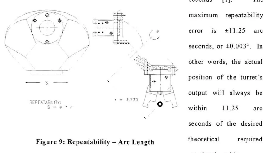
The
maximum
repeatability
error
is
11.25
arcseconds,
or0.003.
In
other
words,
the
actualposition of
the
turret's
output will always
be
within
11.25
arcseconds of
the
desired
theoretical
requiredrotational position.
22H
REPEATABILITY: S = <8
3.730
J\
j
u
Figure
9:
Repeatability
-Arc
Length
To
visualizethis
repeatability
atthe
end effector's or gripper's pickpoint,
it
is
assumedthat this
pointis
3.73
inches
from
the
axis ofrotation ofthe turret
(see
Figure 9).
This
translated
repeatability
canbe
estimatedby
the
arclength
formula,
S
=6*r
(3)
where
S
is
the
repeatability
atthe
end effector's pickpoint,
6 is
the
rotationalrepeatability
ofthe
turret's
outputin
radians,
and ris
the
perpendiculardistance
between
the
pick point andthe
axis of rotation.Theoretically,
withthe
use ofEquation
(3)
andthe
rated values ofturret repeatability, the
end effector'srepeatability
atits
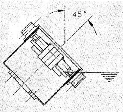
[image:27.551.71.492.143.389.2]The efficiency
of aharmonic drive
gear set varies withspeed, ratio,
lubrication,
andtemperature.
Measured
on actual shaft-to-shaftlosses
ratherthan tooth
losses,
standardharmonic drive
gearing
efficiencies arenormally in
the
80
-90%
range
[1].
Efficiency
is high
for
these
single-stagehigh-ratio drives.
Inherent
powerlosses
in
harmonic drives
aredue
primarily
to
rolling
friction
in
the
wave generatorbearing.
It
.. ;.-.. :.
*.
is
recommended
that the
harmonic drive be
\
45
kcFigure
10:
ATF
Level In Transmission
operated
in
abath
of oil or grease.Higher
speeds can
be
achieved with oil.In
this
case,
automatictransmission
fluid
(ATF)
is
use
in
the transmission
housing
(see Figure
10)
[1].
Because
harmonic drives
are notsubjected
to
sliding
friction,
they
exhibitno stiction
(stick-slip
motion)
upon startup.Consequently,
starting
torque
variationsare minimal.
Harmonic drive
gearing
has
an averagelife
of over15,000
hours
at ratedloads.
The
operating
life
expectancy
ofaharmonic drive
gear setis based
onthe
life
ofthe
ball
bearings
usedin
the
wave generator when runcontinuously
at ratedtorque.
As
long
asthe
gear setis
mounted andlubricated
properly, the
life
ofthe
gearteeth
willbe
wellin
excess of
bearing
life,
provided maximum speed andtorque
limits
are not exceeded.Flexspline life is
virtually
infinite
aslong
asconcentricity
requirementsbetween
the
[image:28.551.64.271.241.428.2]impact
ofstepping
motors orfrequent
starts, stops,
and reversals.Ratings listed for
aharmonic
drive
gear set arefor
a continuousinput
speed of1,750 RPM
andhave
anL,0
life
of3,000
hours based
onthe
bearing.
However,
averagelife is
5
times this
amount[!]
Torque
ratings andlife expectancy
for
speeds otherthan
1,750 RPM
canbe
calculatedby
the
following
[1]:
Tr
=(N/
1750)1'3 *T
(4)
Lio
=(TL
/
Tr)3*
3000
hours
(5)
Where, TL
=listed
torque*rating
at1,750 RPM
Tr
=equivalent
1,750 RPM
torque*rating for
various speedsT
= meanappliedtorque*
Lio
=predicted
life
(hours)
N
= meanspeed
(RPM)
*
Units
of
torque
mustbe
consistent when usedin
the
above equations.A
disadvantage
ofharmonic
drive
transmissions
is
a characteristictermed
"wind-up".
Wind-up
is
the torsional
deflection
that
occursbetween
the
input
andthe
output as atorque
load is
appliedto the
output.The
amount ofthis torsional
deflection
is defined
by
the torsional
spring
rate,
whichis
typically
measuredin
units oflb-in/radian.
The
majority
ofthis
deflection
occursin
the
flexspline due
to
its
thin
walled cross section.This
is
not a major concernin
this turret tool
changerapplicationbecause
there
will notdrive
werelifting
aload
orholding
torque
while positionalaccuracy
was critical.The
only
possiblescenariothat
could effectthe
harmonic drive
withwind-up
is
if
there
wasan end effectorwith a picked part on one side of
the turret
head
that
was muchheavier
than
one onthe
other sidecausing
animbalance.
If
this
were a majorconcern, the
angular
deflection
atthe
output canbe
compensatedthrough the
programming
ofthe
controller.
There have
been
papersthat
have been
written aboutthe
dynamics
and control ofinstrumented
harmonic
drives
[11,12].
One
ofthe
mostcommonly
known
disadvantages
ofharmonic drives is
the
existence of mechanicalflexibility
mentionedabove.
In
keeping
withthe topic
ofthe
design
of aturret tool changer, the
in-depth
theory
ofthe
dynamics
and control of each element ofthe
harmonic drive is
notdiscussed.
Harmonic
drive
transmissions
providethe
high
rotational and positionalaccuracy
required of precision
drive
mechanisms and control systems essentialin
today's
advanced
industrial
robots.Harmonic
drive
transmissionshave
been widely
utilizedin
multi-jointed electro-mechanical and
hydro-mechanical
robotsto
rotatethe
body,
raiseand
lower
the arms,
bend
the elbows,
and rotatethe
wrists.Precision
and compactharmonic
drive
actuatorsfind
wide usein
optical spectrumanalyzers,
and othermeasuring
instruments providing
micro-motion control.Metal
working
machines such as cnc pipebenders
and presses requirevery
accurate motionmachines,
NC lathes
andmilling
machines,
electro-discharge machines andmachining
centers.
Revolving
tool turrets
andtool
magazines alsoemploy
harmonic drive
gearing
in
their
construction.Harmonic
drive
gearing
is
wellknown
for
its
performance andflexibility
in
applications
requiring
controlled variable speed andphasing
ofrotary
shafts.They
arealso used
in
adifferential
configurationfor
webtensioning
and roll registrationmachines
due
to their
smooth motion andbacklash-free
operation.Other
applicationssuch as communication
equipment,
solarenergy
applications, medical,
and electronicparts production equipment
employ
harmonic
drive gearing
asthe
primary
transmissionCHAPTER
VIII.
TURRET HEAD INTERIA
Figure
11:
Turret
Head
Inertia
Setup
[14]
It is necessary
to
find
the
inertia
ofthe turret
head
to
verify
that the
motor
is
powerfulenough
to
accelerateand
decelerate
this
mass.
Due
to the
many
components
that
comprise
the
turret
head,
it
is
ratherdifficult
to
calculatethe
rotational
inertia
ofthis
mechanism.
Using
anexperimental
setup
(see
Figure
11)
that
is
described
below,
the
rotational
inertia
wasestimated.
A rotating
body
whose massis
m,
is
suspendedby
two
vertical wires ofdistance 2a
apart and each of
length
h.
The
center ofgravity
is
onthe
verticalline
that
passes [image:32.551.75.501.126.563.2]turned through
a small angle aboutthe
vertical axisthrough the
center ofgravity
andis
then
released.The
period of oscillation(seconds
peroscillations)
is defined
asT.
The
moment of
inertia
aboutthe
vertical axisthat
passesthrough the
center ofgravity
canthen
be found
by
the
following
equation.J
='
1
i
a
mg
\lnj
h
(6)
Equation 6
canbe found
by
assuming
the
body
rotates at a small angle0 from
the
equilibrium position where
the
force
in
each wireis
F.
Then
the angle, <|>, that
eachwire makes with
the
verticalis
small.Angles 0
and (j) are relatedby
aO
=h(j)
Such
that:
<f> =(7)
h
The
vertical component offorce
F in
each wireis
equalto
mg/2 andthe
horizontal
component of
F
is
mg((>/2.The horizontal
component ofF
ofboth
wires produce atorque
mg<t>ato
rotatethe
body.
Thus using
the
rotationalanalog
ofNewton's
secondlaw for
a singleparticle, the
equation ofmotionfor
the
oscillationis
J9
=-mgda=-mgor
0
+^-^-6
=0
(8)
h
Jh
from
whichthe
periodT
of oscillationis
found
asr
=-4=(9)
This
finally
givesT
=period ofoscillation
(seconds
peroscillation)
2a
=distance between
wires
(m)
h
=length
of wires
(m)
mg
=weight of object
(kg
m/
sec2)
The
test
was performedto
find
the
rotationalinertia
ofthe
populatedturret
head
rotating
aboutthe
axisin
whichit indexes.
The
test
was performedten times to
find
the
period of oscillation and all
ten tests
were equal(repeatable).
The
turret
head,
whilehanging
from
the
string,
was rotated at a small angle andlet
go.The
number ofoscillations was counted
for
1
minutefor
eachtest.
The
averagetime
for
oneoscillation was
then
calculatedfrom
that
information.
In performing
this analysis,
it
was assumed
that the
center ofgravity
is located
along
the
axis of rotation.The
following
data
werefound.
2a,
m.a,
m.h,
m. osc./
minT,
sec./
osc.TEST
0.0635
0.03175
0.5969
38
1.579
]
J
=2
2a
mg
h
2
2
a
w
h
(10)
Where,
w =mg.
Finally,
the
inertia
ofthe turret
head
while populated with6
small endeffectors
if
calculated asfollowed.
J
n.579V.031752*13.35
2n
J
.5969=
.00143
kgm:
With
this
information,
motor selectiondetails
willbe
discussed
in
the
following
chapter.
CHAPTER
IX.
TURRET MOTION
CONTROL
6 PLUG STRIP 120 VAC COMPUMOTOR OEM670T DRIVE COMPUMOTOR 0EM300 75 VDC POWER SUPPLY COMPUMOTOR VM50 I/O INTERFACE CARD COMPUMOTOR OEM6250 CONTROLER RADIO SHACK 120 VACThe
turret tool
changeris
driven
by
a3
phaseDC
servomotor madeby
Compumotor
(model
#SM161AE-N10N).
The drive
that
is
usedto
control poweris
aCompumotor
OEM670T
torque
servodrive.
A Compumotor OEM300
powermodule,
rated at200
watts
(continuous),
is
used
to
supply
75
volts
DC
to the
drive.
A
Compumotor,
OEM6250,
2-axis
servo controller
is
used
to
manipulatethe
control andlogic
sent
to
the
motoralong
withthe
motor's
built-in
Figure
12: Motion Control Equipment Box
rotary
encoderproviding closed-loop
positionalfeedback.
The
computerinterface is
controlledby
awindows
based
program calledMotion
Architect
version3.32
through
anRS-232C
port.Factory
specificationsfor
each product arelisted
in
the
Appendix
F.
Some important
features
ofthe
apparatus arelisted
anddiscussed
below.
A box
was madeto
contain allof
the
pneumatic and electrical control equipment.See
Figure 12
for
anillustration
ofthe
contents ofthe
box.
POWER SUPPLY: 5 VDC & 24 VDC
[image:36.551.62.496.201.487.2]The
Compumotor
SMI 61
brushless
servomotor was selectedto
accommodatethe
requirements of
the turret
tool changer's motion.This
motor metthe
minimum speedrequirement of
1
revolution per second ofturret
output speeddue
to
its
rated motorspeed of
7,500
rpm.This
motoris
capable ofproviding up
to
2.5
revolutions persecond
using
the
50:1
transmission,
however,
that
is
underconstantvelocity
conditions.The
motor alsohas
a rated peaktorque
of847
N-mm.
This
torque
is
more thansufficient
to
acceleratethe turret
head.
This
conclusion was madeby
finding
the
acceleration and
deceleration in
orderto
rotatethe turret through
360in 1
second.It
would accelerate
in 1/2
second anddecelerate
the
other1/2-second.
To
move 180in
1/2
second, the
acceleration wouldbe
25.12
rad/sec2
by
using
Equation
11
(initial
position and
velocity
are zero).0
=(11)
2
r=
Ia
(12)
Using
Equation
12
with a populated turrethead's
inertia
of1425
Kg-mm2,
this
wouldproduce a
turret
head
torque of35.796 N-mm
or5.069
oz-inches.Since
this
motionis
being
translated through
a50:1
gear reducer andthe
harmonic drive
is
a puretorque
couple, the torque
is
then
1/5 0th
ofthe
above value:0.7159 N-mm
or0.1014
oz-inch.This
motor well suitesthe necessary
torque and speed requirements with alarge factor
The
motor comes equipped with a4,000
pulse per revolutionincremental
encoderfor
a closedloop
systembetween
the
motor andcontroller.
The
controller,
however,
is
capable ofhigher
encoder resolution.
The
resolutionand positional
accuracy
is
alsomagnified
50
times
due
to the
50:1
speed reducer.
The Compumotor OEM670T drive
delivers
the
proper powerto
the
brushless
motor andthe
encoder.The
drive
contains a six-stagedrive
design
withhall
effect sensorsfor
commutation.It
has
the
capabilities
for shutting
the
systemdown if
the
motor runstoo
hot
andit has
over-voltage
circuitry,
which would protectthe
drive
from
large
inertial
loads.
The drive
is
powered
by
aCompumotor OEM300
powersupply
that
delivers
75
voltsDC
at2.7
amps.
The
powersupply
can operate on120
or240
VAC
andhas
all ofthe
short-circuit,
over-voltage,
andover-temperature protectionsincorporated
in it.
TIME. SEC.
c
m
p n
\ a
TIME, SEC.
fi n
IS, m
[image:38.551.78.491.78.492.2]o
The Compumotor
OEM6250
is
a controller capable ofoperating
2
axis.It
has
a+/-10VDC
-12
bit
analog interface
withincremental
encoderfeedback.
It
controlsthe
OEM670T drive
in velocity
ortorque
mode.The Controller
alsohas
ahome,
CW
andCCW
end-of-travellimit
per axis.There
are sixteen programmableinputs
and eightprogrammable outputs.
These
inputs
and output werenecessary for
the
gripper'spneumatic actuation and
feedback
from
sensorsif
any.The
controllerhas
two
RS-232C
communicationports
that
connectto
the
COM
ports of aPC.
There
is
another powersupply in
the
systemthat
powers5VDC
to the
controller and24VDC
to the
homing
sensor and all programmable outputs.This
also powersthe
lights
and can alsobe
usedto
power other sensorsif
needed.The
controller requires a6000
seriesbased
program calledMotion
Architect.
It is
awindows
based
programthat
allowsthe
userto
setup
all parameters requiredto
operatethe
motor and encoder.This
program can operatemany different
powerproducts suchas servo and stepper motors and several
logic
controllers.There
areonly
three wiresthat
connect a personal computer'sCOM
portto the
controller'sRS-232C
port.In Motion
Architect,
there
is
asetup
menu whichis
a system configuration and codegenerator
that
allowsthe
userto automatically
generate controller code ofbasic
systemset-up
parameters such asinput
and outputdefinitions,
encoderoperations,
drive
setup,
etc.
Based
onthe
answersthat the
usergivesto the
dialog
boxes,
astartup
program canThe
program editorportion ofMotion
Architect
allowsthe
userto
createblocks
orlines
of
6000
series controllercode,
orcopy
portions of codefrom
a previousfile.
One
cansave editor
files for
later
usein
ahigh level
program such asBasic
orC,
orin
the
terminal
or panel modules(discussed
below).
Any
programthat
is
generatedusing
Motion
Architect
canbe
saved onthe
hard drive
ofthe
PC
andthen
downloaded
to the
controller which
is
then
savedin its
own non-volatile memory.A
terminal
emulatormodule allowsthe
userto
communicatedirectly
withthe
controllerby
typing
in
andexecuting
controller code.It
also givesthe
userthe
capability
ofdownloading
oruploading
saved program codeto
andfrom
the
controller's non-volatilememory.
The
panel module allowsthe
userto test the
controller programs with their owntest
panel.
The
user can customizethe
panel with multiple windows whichdisplays
monitored controller output.The
user can alsoprogrambuttons for
userinput
andfast
command execution.
This
is
the
modulethat
most ofthe
programmer'stime
is
spend after astartup
programis
generated.Refer
to
Figure 14 for
an example of a usertest
panel
that
was madeto
controlthe turret.
Monitoring
the
controller's operation canbe
helpful
in
most cases.Many
windows canbe
openedat onceto
monitor controllerinformation
such as programmableI/O,
analog
I/O, limits,
motormotion,
encoderposition, velocity,
axis and systemstatus,
timers,
Setting
up
userdefined buttons
areextremely
usefulfor fast
command executionfrom
just
a click of a mousebutton.
A
test
panel was setup
for
the turret tool-changer
application and
the
user ofthe
panel can monitorthe
position ofthe
turret, home
andend-of-travel
limits,
and axis and system status.The
panelhas
a communicationswindow,
whichfunctions just
the
same asthe terminal
module.This
allowsthe
userto
execute
individual
lines
of codeif
needed.There
are32
buttons
that
have
been
programmed which allows
the
userto
executemany lines
ofpreprogrammed codefor
end effector
actuation,
teaching
points,
finding
home
position,
andshutting down
the
system
if
user panic mode setsin.
A
few
ofthe
buttons
have
been
designated
for
program execution.
Some
ofthe
programs will promptthe turret to
gothrough
a seriesof movements
to
display
its
motion,
end-effectoractuation,
and combined movementand end effector actuation.
See
Appendix D for
programsthat
have
been
writtenusing
SH9'?V9Rl*VV'rWfGBTfWtf)fttlTflWVHVrniHHH^HHH te gisyhnys Vtew SetSrqs Jransfera j^ifwJw.ye.Sp..
[Axis1,ActualPosition(counts)Ip I
JAwslCommandedPosition^counts}JO
.U3L*H
Bit 1. Axis 1 POS(CW)Limil Folso Brt 2. A>k1NEGfCCV*)LimitFalse Brt 3. Axis1Home Limit False
*
h^LL
Sill, MovingStatus NotMoving Bit 2. Direction Status POS(CW) Bit 3. Acceleration Status NotAccelerating Brt 4.VelocityStatus No!Atvelocity
Bit5,HomingStatus Not Successful BrtS.Absolute/Incremental Incremental Brt7.Continuous/Preset Preset Brt 8.JogMode No Brt13. Dnve Shutdown No 8rt 14. Drive Fault N
![Figure 1: Robohand Turret Tool Changer [5]](https://thumb-us.123doks.com/thumbv2/123dok_us/59542.5544/8.551.75.487.144.481/figure-robohand-turret-tool-changer.webp)

![Figure 6: Harmonic drive components [1]](https://thumb-us.123doks.com/thumbv2/123dok_us/59542.5544/22.551.68.466.89.270/figure-harmonic-drive-components.webp)
![Figure 7: Principles of operation [2]](https://thumb-us.123doks.com/thumbv2/123dok_us/59542.5544/23.551.64.489.186.524/figure-principles-of-operation.webp)