Int. J. Electrochem. Sci., 14 (2019) 1876 – 1883, doi: 10.20964/2019.02.39
International Journal of
ELECTROCHEMICAL
SCIENCE
www.electrochemsci.org
Short Communication
Influence of AC interference on Crack Initiation Behavior of
Pipeline Steel in High pH Solution
Min Zhu*, Yongfeng Yuan, Qiang Zhang, Simin Yin, Shaoyi Guo
School of Mechanical Engineering & Automation, Zhejiang Sci-Tech University, Hangzhou 310018, PR China
*E-mail: [email protected]
Received: 30 October 2019 / Accepted: 26 November 2018 / Published: 5 January 2019
Stress corrosion cracking (SCC) behavior of U-bend samples of X80 steel under AC application was investigated in high pH solution by scanning electron microscopy (SEM), macroscopic observation and polarization curves. The results show that there is a remarkable difference in corrosion morphologies of steel samples tested with or without AC current. AC application enhances the corrosion of X80 steel, and results in the occurrence of pitting corrosion. With the increasing AC current density, the corrosion degree of steel increases and the pits become more apparently. The pitting corrosion generated due to applied AC induces and facilitates the crack initiation, the greater of AC current density, the more cracks are initiated from the pits, and thus increases the SCC susceptibility of the steel.
Keywords: Pipeline steel; SCC initiation; AC application; Pitting corrosion
1. INTRODUCTION
The specimens were cut from hot-rolled plate of API X80 pipeline steel. The chemical composition of the steel is (wt%): C 0.070,Si 0.216, Mn 1.80, P 0.0137,S 0.0009,Mo 0.182,Cr 0.266,Cu 0.221, Ni 0.168, Nb 0.105, Al 0.026, Ti 0.013, V 0.001, N 0.003 and Fe balance. The microstructure of the steel is mainly composed of polygonal ferrite, acicular ferrite and a number of granular bainites (Fig.1).
As illustrated in Fig.2a, the U-bend specimens were prepared according to GB T 15970 specification. Prior to the test, the surface of the U-bend specimen was ground to 2000 grit emery paper along the tensile direction, then degreased with acetone, followed by cleaning with distilled water and finally dried in air. The specimens were coated with a silicone, leaving an exposure area of 2 cm2 as the
working surface. According to the design thinking of the test, the exposure area was the part of high ridge of the specimen, i.e., the region of the maximum strain, as shown in Fig.2b. In the laboratory test, the carbonate/bicarbonate solution (0.5 MNa2CO3+1 MNaHCO3) was widely used as the simulated
solution for high pH SCC of buried pipeline steels. The pH of the solution was 9.32. The U-bend specimen was immersed in the solution, and AC current density in the range of 0-200 A/m2 was applied
to the sample. During the whole process of immersion test for 30 days, the sine wave AC with a frequency of 50 Hz was applied between the specimen and graphite electrode, meanwhile, the sample was conducted at a polarized potential of -580 mV (vs SCE). The potential applied to the specimen was in the middle of the potential range causing IGSCC [13]. The sample was maintained at the potential via a PS-12 potentiostat and a three-electrode system, where the U-bend sample was used as the working electrode, a platinum plate as counter electrode and a saturated calomel electrode (SCE) as reference electrode. The test was performed at ambient temperature (~22℃) and repeated at least three times. After the test, the corrosion morphology of high ridge region of the specimens at various AC current densities was analyzed by scanning electron microscopy (figure 6) (SEM), macroscopic observation(figure 3-4) and 3D imaging (figure 5).
Figure 1. Metallograph of X80 pipeline steel
Figure 2. U-bend sample (a) sketch map, (b) coated specimen
3. RESULTS
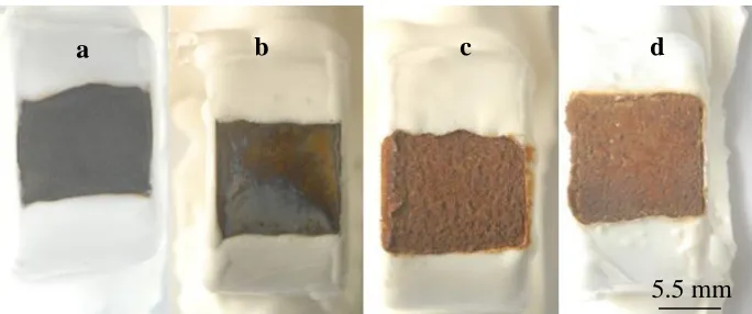
Figure 3. Macro-morphologies of U-bend sample of X80 steel at various AC current densities in carbonate/bicarbonate solution (a) without AC, (b) 30 A/m2, (c) 100 A/m2, (d) 200 A/m2.
Fig.3 shows the macro-morphologies of U-bend sample of X80 steel at various AC current densities. At the absence of AC superimposition, the steel surface is covered by black corrosion product,
7 mm
a b c d
a b
[image:3.596.186.409.67.231.2] [image:3.596.157.445.272.431.2] [image:3.596.129.471.526.669.2][image:4.596.131.469.205.345.2]
Figure 4. Macro-morphologies of U-bend sample of X80 steel at various AC current densities in carbonate/bicarbonate solution following the removal of corrosion product (a) without AC, (b) 30 A/m2, (c) 100 A/m2, (d) 200 A/m2.
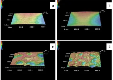
Figure 5. 3D imaging of corrosion morphologies of U-bend sample of X80 steel at various AC current densities in carbonate/bicarbonate solution following the removal of corrosion product(a) without AC, (b) 30 A/m2, (c) 100 A/m2, (d) 200 A/m2.
a b c d
c d
b a
[image:4.596.105.494.416.694.2]
Fig.4 shows the macro-morphologies of U-bend sample of X80 steel at various AC current densities following the removal of corrosion product. It is clearly shown that there is a significant difference in the corrosion morphologies of specimens with or without AC application. As Fig.4a reveals that, when AC current is absent, no obvious pits are observed on the surface of sample. Under the macroscopic observation, the morphology feature of specimen at 30 A/m2 is analogous to that at the
absence of AC. With the increasing of AC current density, the pits become more apparently, and the pit number greatly increases, resulting in an intensive distribution on the whole surface of steel sample.
Figure 5 shows 3D imaging of corrosion morphologies of U-bend sample of X80 steel at various AC current densities following the removal of corrosion product. The images reveal that the increasing of AC current density obviously promotes corrosion degree of the steel, and accelerates the occurrence of localized corrosion. Especially at high AC current densities of 100 A/m2 and 200 A/m2, the severe pits
can be observed on the surface of U-bend samples, and some corrosion pits are very large and deep. Furthermore, some small-sized pits fuse together and form a larger-sized pit. In contrast, the degree of pit corrosion on the surface of the samples tested without AC application or at the low AC current density of 30 A/m2 is relatively slighter.
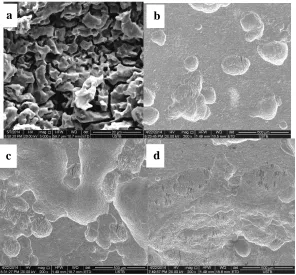
The above corrosion morphologies (Fig. 3-5) are based on macroscopic or low magnification observation. Fig.6 shows the micro-morphologies of U-bend sample of X80 steel at various AC current densities following the removal of corrosion product. There is a remarkable difference in micro-corrosion morphologies of steel samples tested with or without AC current. It is seen from Fig.6a that, the cracks are intergranular, and there is an apparent phenomenon of grains removal, which are identical with the feature of IGSCC fracture. In contrast, under AC application, there are obvious pits formed on the specimens at various AC current densities. With the increasing of AC current density, the number and size of pits increase significantly. In particular, the small pits are connected into the big one, even at 30 A/m2. Moreover, Fig.6b, c and d shows that the SCC cracks are initiated from the pits. In addition,
the greater AC current density, the more cracks are initiated from the pits. This is verified that the pitting corrosion induced by AC facilitates the crack initiation [11], which greatly increases the SCC susceptibility of the steel, and accelerates the crack propagation at some extent [12]. Furthermore, the significant difference in micro-corrosion morphology of specimens demonstrates that the SCC mechanism of steels tested with or without AC in high pH solution is remarkably different [11].
Figure 6. Micro-morphologies of U-bend sample of X80 steel at various AC current densities in carbonate/bicarbonate solution following the removal of corrosion product (a) without AC, (b) 30 A/m2, (c) 100 A/m2, (d) 200 A/m2.
1E-6 1E-5 1E-4 1E-3 0.01
-1.0 -0.5 0.0 0.5 1.0 1.5
E
/V
I/Acm-2
0 A/m2 30 A/m2 50 A/m2 200A/m2
Figure 7. Polarization curves of U-bend sample of X80 steel at various AC current densities in carbonate/bicarbonate solution
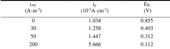
Fig.7 shows the polarization curves of U-bend sample of X80 steel at various AC current densities. Superimposed AC significantly reduces the passivity of steel under the strain state. AC application mainly affects the anode curves, which increases the passive current density (ip) and shifts
the critical pit potential (Eb) negatively. Table.1 reveals that imposed AC greatly promotes the ip value,
i.e. AC application accelerates the corrosion rate of steel, especially at the high current density of 200
[image:6.596.151.447.69.344.2] [image:6.596.157.418.421.616.2]
A/m2. Table.1 also shows that AC shifts E
b value negatively at a great extent, which indicates that pitting
corrosion could be easily formed on the sample surface, even at the low AC current density of 30 A/m2.
[image:7.596.159.436.248.328.2]This can be verified in Fig.6. It is well known that pits corrosion could accelerate the initiation of crack. As shown in Fig.6, the pitting corrosion generated by applied AC could increases SCC susceptibility. At high pH solution, the SCC behavior of pipeline steel is related to the rupture of passive film [15-16]. The curve change in Figure 7 demonstrates that AC could decrease the film stability, which could accelerate the SCC process.
Table 1.Fitted electrochemical parameter of U-bend sample of X80 steel at various AC current densities in carbonate/bicarbonate solution
iAC
(A·m-2)
ip
(10-5A·cm-2)
EB
(V)
0 1.038 0.855
30 1.258 0.403
50 1.447 0.312
200 5.666 0.112
4. CONCLUSIONS
AC interference obviously promotes corrosion degree of U-bend sample of X80 pipeline steel, and accelerates the occurrence of pitting corrosion. With the increasing AC current density, the corrosion degree of steel increases and the pits become more apparently. Pitting corrosion generated by applied AC induces and facilitates the crack initiation, the greater of AC current density, the more cracks are initiated from the pits, and thus increases the SCC susceptibility of the steel.
ACKNOWLEDGEMENTS
This work was support by the National Natural Science Foundation of China, the Natural Science Foundation of Zhejiang province (No. LY18E010004), and the National R&D Infrastructure and Facility Development Program of China (No. 2005DKA10400).
References
1. S.B. Lalvani and G. Zhang, Corros. Sci., 37(1995)1567.
2. A. B renna, S. Beretta, F. Bolzoni, M.P. Pedeferri and M. Ormellese, Constr. Build. Mater., 137(2017) 76.
3. Y.B.Guo,T.Meng, D.G.Wang,H.Tan and R.Y.He, Eng.Fail.Analy., 78(2017)87. 4. K.K.Tang, Cement concrete Res., 100(2017)445.
5. Nagat M. K. Abdel-Gawad, Adel Z. El Dein and M. Magdy, Electr. Pow. Syst. Res., 127(2015)297 6. J.L. Wendt and D.T. Chin, Corros. Sci., 25(1985)889.
7. A.Q. Fu and Y.F. Cheng, Corros. Sci., 52(2010)612.
8. Y.B. Guo, H. Tan, D.G. Wang and T. Meng, Anti-Corros. Method.M., 64(2017)599. 9. B.G. Van, W. Chen and R. Rogge, Acta. Mater., 55(2007)29.
10.W. Chen, F. King and E. Vokes, Corrosion, 58(2002)267.