Measurements of Residual Stress and Microstructural Evolution in Electron
Beam Welded Ti-6Al-4V Using Multiple Techniques
William Raea,*
[email protected] Zak Lomasb
Martin Jacksonc Salah Rahimia
a Advanced Forming Research Centre (AFRC), University of Strathclyde, 85 Inchinnan Drive, Inchinnan, Renfrewshire PA4 9LJ, UK
b Rolls-Royce plc, PO Box 31, Elton Road, Derby, DE24 8ED, UK
c Department of Materials Science and Engineering, The University of Sheffield, Mappin Street, Sheffield S1 3JD, UK
* Corresponding author
Abstract
The evolution of residual stress and microstructure has been investigated in electron-beam welded Ti-6Al-4V alloy rings in order to develop an understanding of how the distribution of through-thickness residual stress correlates with microstructural evolution. A multiple technique approach to residual stress measurement was employed using a combination of different measurement techniques including X-ray diffraction (XRD), hole drilling method based on electronic speckle pattern interferometry (ESPI), and the contour method. It was found that there is a strong correlation between the change in residual stress and alpha phase morphology across the weld. The fusion zone exhibited highly tensile residual stress which was typified by an entirely acicular α′ microstructure formed by a displacive transformation within prior β grains on cooling. The tensile residual stress in the centre of the weld reduced towards the heat affected zone, transitioning to a compressive residual stress upon increasing distance from the weld centre. The transition from tensile to compressive residual stress correlates with a significant decrease in the volume fraction of α′ and an increase in the bimodal morphology of equiaxed primary alpha in a diffusional transformed beta matrix leading to elongated alpha in the base material.
Keywords
X-Ray Diffraction Weld1. Introduction
Titanium alloys are often selected as structural components for use in a number of applications due to their favourable strength-to-weight ratio, corrosion resistance and temperature resistance [1]. The aerospace industry accounts for majority significant amount of global titanium consumption (i.e. over 50%) and is commonly used in the airframe, landing gear and gas turbine engines [2]. The sixty-year-old α + β type alloy Ti-6Al-4V is the most widely used titanium alloy, acting as an integral constituent of many aerospace components.
Joining technologies are essential to the manufacture of gas turbine engine parts; therefore ensuring structural integrity is pivotal to the endurance of critical components in service. Electron-beam welding is one of the most popular joining techniques in the manufacture of gas turbine engines. Electron-beam welding produces three distinct zones in the welded material including the fusion zone (FZ) which undergoes melting and re-solidification, the heat affected zone (HAZ) which is subjected to a solid state thermal cycle, and the base metal (BM) which is largely unaffected by the welding process [3]. The application of heat treatment can potentially lead to tailored mechanical properties in Ti-6Al-4V, however, thermal gradients during welding typically result in undesirable changes to the original microstructure, causing deviations from bulk mechanical properties [4]. This presents a number of challenges, most notably in the formation of undesirable residual stress and microstructure [5].
Most manufacturing processes such as forging, welding, machining and quenching are associated with the generation of residual stress [6]. Residual stresses can be thought of as internal stresses, required to maintain equilibrium, which remain in a part when it is no longer subjected to any external applied loads [7]. These residual stresses can be induced by heterogeneous plastic deformation, differential thermal fluctuations or due to phase transformation and precipitation [5]. Thus, residual stresses are often generated due to welding operations, as at least one of these mechanisms occurs during welding [8-10].The inclusion of undesirable residual stress (i.e. tensile) can be detrimental to the life of a component [11, 12]. A recent review by Fairfax and Steinzig [13], which analysed 147 residual stress related incidents within the ASM Failure Analysis Database™, found that over 37% of incidents were directly attributable to joining-related failures. Additionally, residual stresses may lead to distortion during the manufacturing process of machining due to material removal which leads to the redistribution of residual stresses [14]. Determining the nature and magnitude of such stresses is therefore of critical importance to the manufacture and performance of welded Ti-6Al-4V components.
Mehdi et al. [16] identified and assessed both the microstructure and residual stress of Ti-6Al-4V tungsten inert gas (TIG) fusion welds. XRD was used to determine that the surface residual stress distribution is related to the prior β grain size in the FZandvolume fraction of different phases across the weld region. However, the use of XRD for residual stress analysis produces a collection of single point surface data, which does not allow for a through-thickness understanding of the residual stress magnitudes and distributions in a component. On the other hand, the contour method can be applied to produce a 2-Dimensional (2D) map of out-of-plane residual stress [21]. The method has also been demonstrated on Ti-6Al-4V extruded profiles [22]. Nevertheless, it has been noted that limitations in Electrical Discharge Machining (EDM) cutting quality can lead to high uncertainties within 0.5 mm of the contour sample edge [23]. Special care can be taken to mitigate these uncertainties, requiring verification by means of additional measurements using techniques such as hole-drilling and XRD [23]. Xie et al. employed the contour method alongside XRD in order to successfully verify the near-surface accuracy of the contour method when applied to 50 mm electron-beam welded Ti-6Al-4V plates [15]. Thus, established methods with low depth penetration such as XRD and hole-drilling techniques can be used to compliment and verify the near-surface results of the contour method. This can lead to a comprehensive understanding of through thickness residual stresses in a part which can then be interrelated to microstructural observations.
Despite the above, little work has been conducted regarding the application of multiple residual stress measurement techniques upon electron-beam welded Ti-6Al-4V to develop an understanding of how the distribution of through-thickness residual stress correlates with microstructural evolution. This paper aims to present a clear understanding of the magnitude and distribution of welding induced residual stress and microstructure evolution in electron-beam welded Ti-6Al-4V. A focus on residual stress measurement was maintained throughout this work, with the resulting findings interrelated to the microstructural evolution and microhardness profile for two weld cases.
2. Material and Methods
2.1 Material and Processing
Fig. 1. Photograph of Ti-6Al-4V welded sample Ring 1.
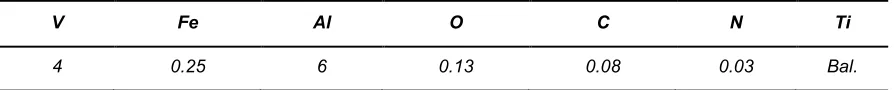
Table 1. Nominal chemical composition for Ti-6Al-4V alloy used in study (wt%).
V Fe Al O C N Ti
4 0.25 6 0.13 0.08 0.03 Bal.
Table 2. Weld parameters and ring dimensions (Note: The weld of Ring 1 was performed in one single pass,
while Ring 2 was subjected to additional cosmetic pass, resulting in two complete passes).
Ring ID
Weld conditions Geometry
Weld speed (mm/s)
Axial clamping pressure (bar)
Weld power
(W)
Cosmetic pass
Outer diameter
(mm)
Height (mm)
Mean thickness
(mm)
1 30 210 14,250 No 353 60 16.8
2 20 ‘low pressure’ 9,000 Yes 353 70 16.4
2.2 Microstructure Characterisation
[image:4.612.42.578.399.521.2]2.3 Microhardness Measurement
In order to provide additional evidence of microstructural evolution in the welded rings, following the microstructural characterisation, a Struers Durascan G5 microhardness testing machine was used to measure a hardness map on the sample cross section; including the BM and different zones of the weld. These measurements were acquired to ASTM E-384-16 standard using a diamond shaped Vickers indenter by applying a 0.5 N load with a 15 s dwell time. Indentations were made on a rectangular grid covering the weld cross section, with 1 mm spacing in both radial direction and axial direction between indentations, and a 1 mm distance between the closest indentations and edge of the sample. Indentations were analysed with a 40 × objective lens, zoom 1, to produce a micro-hardness map.
2.4 Residual Stress Measurement
Residual stress analysis was carried out on each welded ring using a combination of (1) XRD, (2) hole-drilling [image:5.612.48.565.406.570.2]
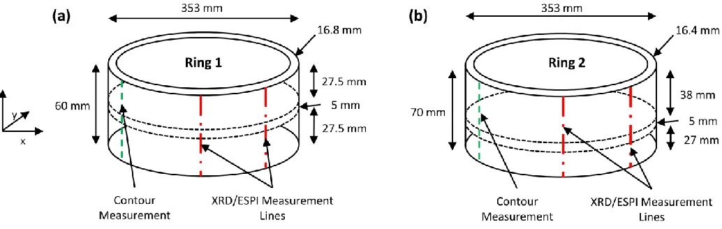
based on ESPI, and (3) the contour method. For each welded ring, one radial cross-section was selected for the contour method, and two measurement lines were identified for XRD and ESPI stress measurements. These are shown schematically in Fig. 2. This allowed for the investigation of the axisymmetric of hoop stresses throughout the rings and, if verified, would provide additional comparison with the contour method results. A number of measurement points were selected in the FZ, HAZ and BM along these surface profiles to provide an understanding of the surface and near-surface residual stress distribution in both axial and hoop directions, and allow for later comparison with the results of the contour method.
Fig. 2. Schematic illustration of the welded rings with position of the welds and the dimensions of the BM
material, (a) Ring 1, (b) Ring 2. The location of contour method residual stress measurements are highlighted in green, and the surface profiles for the XRD and ESPI based hole-drilling measurements are highlighted in
red.
2.4.1 X-ray Diffraction
Young’s modulus of 118 GPa and Poisson’s ratio of 0.342. At least nine measurements were performed on the identified surface profiles for each ring (see Fig. 2) in both hoop and axial directions, at points with higher density in the weld regions and with increased point spacing towards the BM material, encompassing the weld and BM on either sides of the weld. For each point in both directions, 11 measurements with a 3 s exposure time for each measurement were performed. These were sufficient to obtain an adequate number of counts to construct strong peaks used for stress analyses. A round collimator with 1 mm radius and ten ψ-offset angles in the range of maximum ± 30° were employed. Separate gain profiles were gathered for the BM, HAZ and FZ to account for variations in Bremsstrahlung background radiation due to the differing fractions of constituent phases present throughout the material.
2.4.2 Hole-drilling with ESPI
Hole-drilling based on ESPI was used to provide near surface measurements of hoop and axial residual stress components at a limited range of successive depths from the surface. This was conducted using a Stresstech Prism® system; which consisted of a high speed drill, laser source, and a CCD camera. The laser source produces a monochromatic wavelength of 532 nm. Tungsten carbide drill bits were used when carrying out the procedure. Two drill bit diameter sizes of 1.8 mm for measurements on the BM, and 1 mm for those on the FZ were used. Holes were drilled at depth increments up to 60% of the drill diameter corresponding to 1 mm depth for the BM, and 0.6 mm for the FZ. For each ring, two sets of measurements were performed in the BM (z = + 20 mm), with a further two in the FZ (z = 0 mm) on the surface profiles, at precisely the same spots as those measured by XRD, shown schematically in Fig. 2. The through depth residual stress profiles were then calculated from the optically measured surface displacement data assuming a Young’s modulus of 118 GPa and a Poisson’s ratio of 0.342.
2.4.3 Contour Method
The contour method was carried out on both welded rings in order to provide a full 2D map of hoop residual stress distribution in the samples. This included the task of releasing bending moments, as described by Prime [26], which act as an additional source of hoop residual stress. The measurement for each ring was carried out in four main steps: (i) sample cut, (ii) measurement of cut surface profiles, (iii) data processing, and (iv) calculation of residual stress using finite element simulations; that are discussed in the following.
was used as the basis for residual stress measurement by contour method. The sample was clamped on both sides of the cut planes appropriately during the cutting process.
Upon completion of the EDM cuts, for each sample the outline and surface topography were measured on either side of the skim cut in a temperature controlled environment using a Mitutoyo Crysta Apex C coordinate measuring machine (CMM) with a 2 mm ruby attached to a Renishaw PH10T touch probe. The CMM equipment was programmed to acquire data with a spatial resolution of 400 µm for points in both in-plane directions.
The measured data obtained for both surfaces of each skim cut were cleaned to minimise outliers and system noise. The data from both sides of the cut were then aligned in the same coordinate system by considering the whole perimeter of each half of the cut as an alignment guide to match the whole outlines. Following the alignment process, the datasets for both sides were linearly interpolated onto a common grid, after which the two sets were averaged. The pitch of the common grid was equivalent to that of the original data in order to produce the average surface point by point. A set of knot spacing ranging from 0.4 mm to 15.4 mm was chosen and a bivariate cubic spline for each knot spacing was fit to the averaged data. A knot spacing of about 4 mm was selected for both rings as an appropriate value.
A 3D finite element (FE) model assuming isotropic elasticity with a Young’s modulus of 118 GPa and a Poisson’s ratio of 0.342 was used to evaluate the residual stress from the surface contour data. For this purpose, the perimeter of the cross-section for each sample was modelled using the aligned outline measured by the CMM. The 2D cross-section was then revolved circumferentially for 180° and 120° to produce 3D models, respectively for the calculations of bending moment induced stress and residual stress. Mesh seeds were attributed to each node on the outline and also along the revolved perimeter of the model that are used as guidelines for the generation of mesh. The establishment of the seeds were biased by allocating a finer pitch near the cross-section of the model representing the cut surface, and coarser pith towards the other end of the model that is of a less importance for stress analysis. The parts were modelled in Abaqus CAE and meshed with an element spacing of 0.8 mm on the cut surface, and 0.8–10 mm with single bias away from the surface. The selected element type was C3D20R; 20 node brick quadratic elements, as used by Prime et al. [27].
3. Results
3.1 Weld Microstructure
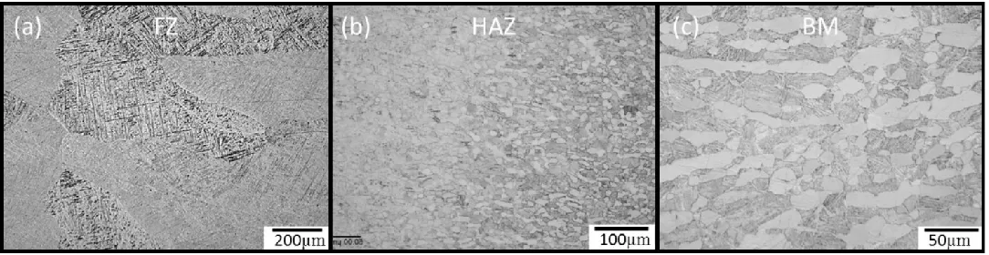
The light micrographs obtained for Ring 1 show three distinct microstructures for different regions of the weld, each characterised by varying microstructural features (Fig. 3). These regions include the FZ, HAZ and BM, the microstructures of which are dictated by the thermal history during welding. It is evident from Fig. 3a that the FZ is almost fully comprised of acicular α′ in prior columnar β grains which is a characteristic of diffusion-less shear transformation of β upon fast cooling from the welding temperature. There is some evidence of epitaxial growth of these columnar FZ grains originating from the HAZ. The HAZ can be characterised as a transition region with regards to microstructure and can therefore be subdivided into the near and far HAZ with respect to the FZ; where the microstructure is dependent on the local temperature in relation to the material’s martensitic start temperature (Ms). It is apparent from the micrograph presented in Fig. 3b that the near HAZ (left) primarily consists of acicular α′, similar to that of the FZ yet with a distinct morphology. The far HAZ (right), however, has a microstructure more representative of the BM. From Fig. 3b there is a visible decrease in the volume fraction of α′ from near to far HAZ as the local temperature during welding decreases below the Ms. As volume fraction of α′ decreases, it is replaced by an increasing presence of fine scale globular α and β lamellae in prior β grains, and equiaxed α at prior grain boundary α (αgb). Therefore between the FZ and the HAZ there is a transition from a shear dominated to diffusion dominated phase transformation. The fine scale primary alpha becomes coarsens and becomes elongated towards the BM, and is shown in Fig. 3c.
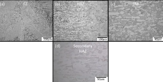
[image:8.612.36.578.506.646.2]Similarly to Ring 1, light micrographs of Ring 2 showed evident signs of microstructurally unique FZ, HAZ and BM regions, as shown in Fig. 4. However, there was an additional ‘secondary HAZ’ attributed to the cosmetic pass (see Fig. 4d), identified as a fourth region close to the outer diameter of the ring; replacing the original FZ in this region, see Fig. 5 for details. There is an evident macrotexture in the secondary HAZ with a directionality towards the centre of the weld. Further increases in magnification revealed faint equiaxed α grains and transformed β, identified as ‘ghost α’, shown in Fig. 4d.
Fig. 3. Optical micrographs of the weld zones of Ring 1. (a) FZ, (b) HAZ, and (c) BM.
Fig. 4. Optical microscopy appearances of the weld zones of Ring 2. (a) BM, (b) HAZ, (c) FZ, and (d)
Observed ‘ghost α’ in the ‘secondary HAZ’ due to cosmetic pass.
Fig. 5. Schematic representation of secondary HAZ formed within the cross section of Ring 2 induced by the
additional cosmetic weld pass.
3.2 Weld Microhardness
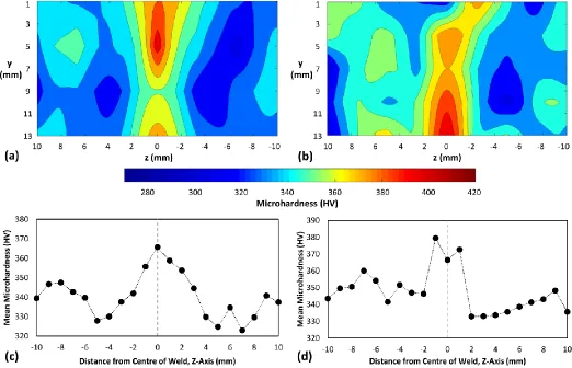
The microhardness results presented in Fig. 6 provide further evidence of microstructural evolution and strength variations across the weld, extending from the BM on one side to the BM on the other side, covering all the regions. An area of 21 mm × 12 mm was considered for each ring; starting at a depth of 1 mm from the outer surface, and axially centred on the weld.
In Ring 1, the maximum microhardness reading was 416 HV, with a minimum of 273 HV; whereas values ranged from 292 to 416 HV for Ring 2. The average hardness was found to increase from ~ 330 HV in the BM to ~ 370 HV in the FZ of both Ring 1 and Ring 2. The obtained microhardness data for the HAZ shows a transition between the FZ and BM for both rings, correlating with the optical micrographs presented in Fig. 3 and Fig. 4.
[image:9.612.198.414.358.459.2]noticeable in Fig. 6b. The line plots of averaged y-axis microhardness across the weld in the z-direction (Fig. 6c and d) further highlight the increased hardness of the FZ compared to the BM in both rings.
Fig. 6. 2-D microhardness maps across the electron-beam welded regionsin (a) Ring 1, and (b) Ring 2.
Accompanying line plot of mean microhardness across the weld in (c) Ring 1, and (d) Ring 2. .
3.3 Weld Residual Stress
Depth profiles of residual stress distribution quantified by hole-drilling based on ESPI for the FZ (z = 0 mm) and BM (z = + 20 mm) of both samples are provided in Fig. 8, displaying the data obtained for both surface profiles (i.e. ESPI 1 and ESPI 2) in the hoop and axial directions. The corresponding surface residual stresses for these zones, as quantified by XRD, are also presented in Fig. 8 for reference. In the FZ, tensile hoop stresses were measured at all depths, with maximum values of + 860 ± 50 MPa at a depth of 0.35 mm for Ring 1 (see Fig. 8a) and + 898 ± 50 MPa at a depth of 0.36 mm for Ring 2 (see Fig. 8c). Axial residual stresses in the FZ of Ring 1 were found to vary between tensile and compressive in nature with very small magnitudes as depth increased (see Fig. 8a). However, axial stresses were found to be mostly tensile for the FZ of Ring 2 (see Fig. 8c), with a maximum value of + 263 ± 50 MPa at a depth of 0.36 mm. Both rings showed a similar trend in BM residual stresses; with highly compressive hoop and axial stresses leading to a relatively stable value (see Fig. 8b and d). This ranged from between roughly 0 to – 50 MPa and – 50 MPa to – 100 MPa for axial and hoop stresses, respectively, at depths of 0.1 mm to 1.2 mm. The ESPI based hole-drilling results provide further confirmation of axisymmetric residual stress distribution; with good accordance between surface profiles upon increasing depth.
Fig. 7. XRD residual stress data across the weld for Ring 1 and Ring 2. (a) Hoop stress, and (b) Axial stress.
Fig. 8. Surface and near surface residual stress profiles measured by XRD and hole-drilling based on ESPI as
functions of depth at different regions of Ring 1 and Ring 2 welds. (a) FZ of Ring 1 at z = 0 mm, (b) BM of Ring 1 at z = + 20 mm, (c) FZ of Ring 2 at z = 0 mm, and (d) BM of Ring 2 at z = + 20 mm.
Fig. 9. Average surface height data measured by CMM for (a) Ring 1, and (b) Ring 2.
Considering the 2D hoop residual stress maps for both rings, it is clear that residual stress in the weld region decreases almost linearly in the – z and + z direction, with Ring 1 and 2 displaying differing linear and hyperbolic shapes respectively. Such a relationship agrees with the microhardness data in Fig. 6 where Ring 1 exhibits a wider region of high hardness over the weld zone compared to Ring 2. This is shown in Fig. 11 by plotting the residual stress profiles across the whole weld cross-section along the z-axis. Additionally, from Fig. 10b it was noted that Ring 2 exhibited a protrusion in tensile residual stress along the inner diameter of the ring, up to roughly 27 mm away from the weld in the – z direction. A corresponding balancing zone of highly compressive residual stress was observed towards the ring inner surface, away from the tensile protrusion, with a maximum value of – 625 MPa.
Plots of surface, near-surface, and through-depth residual stress were produced by combining the results of
Fig. 10. Out-of-plane 2D hoop residual stress maps of samples as determined by the contour method and
bending moment for (a) Ring 1, and (b) Ring 2.
Fig. 11. Residual stress profiles across the weld cross-section (i.e. along the z-axis in Fig. 10) taken from the
[image:14.612.50.567.448.620.2]Fig. 12. Combined results of XRD, hole-drilling based on ESPI and contour method hoop residual stress as
functions of depth (y) within 2.5 mm of the outer surface for (a) FZ of Ring 1 at z = 0 mm, (b) BM of Ring 1 at z= + 20 mm, (c) FZ of Ring 2 at z = 0 mm, and (d) BM of Ring 2 at z = + 20 mm.
The plot of surface and near-surface depth stress profile of the FZ of Ring 1 (see Fig. 12a) displays tensile data for all applied techniques. Upon consideration of the depth plot in the BM of Ring 1 (see Fig. 12b), the residual stress distribution is shown to be compressive for all points. Similarly, all data points for the FZ (see Fig. 12c) and BM (see Fig. 12d) of Ring 2 are tensile and compressive, respectively. There is good agreement between contour results and ESPI based hole-drilling data in the FZ and BM of both rings. This is especially evident in the BM of Ring 1 and Ring 2 from depths of 0.5 mm to approximately 1.15 mm, with all contour and ESPI data within the bounds of measurement error throughout this range [23].
4. Discussion
The residual stress profiles obtained using XRD, hole-drilling with ESPI and the contour method showed good
to the selected element size being too large and/or the selected spline knot spacing over-smoothed the surface topography data, and in turn affecting the residual stress results [28]. Knot spacing and element size selection also leads to extracted contour data points representing a number of small segments with averaged residual stress in place of point measurements (e.g. XRD or ESPI based hole-drilling) which can better capture peaks in residual stress [23]. For the purposes of understanding bulk residual stress distributions across the weld, the wavelength covered by the contour method is adequate. However, it is also often important to have an understanding of surface and near-surface residual stresses with high spatial sensitivity due to the role of such residual stresses during fatigue crack initiation [7]. Therefore, the utilisation of XRD and ESPI based hole-drilling proved complimentary to the contour method by offering a means of contour verification as well as determination of high fidelity surface and near-surface residual stress with relatively short wavelength which cannot be captured accurately by contour method.
The general 2D through thickness distribution of hoop residual stresses in both rings, as presented by the
contour method, depicted a tensile region in the FZ. This decreased in magnitude across the HAZ, developing into highly compressive pockets in the BM, and then slightly decreasing in magnitude to a relatively steady compressive value as distance from weld increased. This distribution is as would be expected for a typical electron-beam weld [3, 15].
The peak tensile hoop residual stresses of both rings were obtained by ESPI based hole-drilling in the FZ.
These were recorded at similar depths; + 860 ± 50 MPa at a depth of 0.35 mm for Ring 1 and + 898 ± 50 MPa at a depth of 0.36 mm for Ring 2. This is similar to the maximum residual stress of + 914 MPa measured by Xie
et al. using the contour method on electron-beam welded Ti-6Al-4V plates of 50 mm thickness [15]. In order to compare the residual stress to the material yield strength, the effect of varying microstructures across the weld must be considered. Wang and Wu linked the microstructure to the yield strength of electron-beam welded Ti-6Al-4V joints, with the BM, HAZ and FZ corresponding to yield strengths of 932 MPa, 892 MPa and 857 MPa respectively [18]. There are differences between the aforementioned study and the work conducted in terms of material geometry, weld conditions and BM microstructure. However, based on these properties the peak tensile stress recorded in the FZ would be in the range of the material yield strength. Such highly tensile residual stress is undesirable and post weld heat treatment may be applied to reduce such residual stresses in industry [3, 15].
Although the obtained data provides evidence to support the expected general trends in residual stress
The residual stress distribution in the FZ of both welded rings was found to be highly tensile throughout. This tensile zone was associated with a peak in microhardness and the observation of an almost entirely acicular martensitic structure in the FZ. Hardness within Ti-6Al-4V welds is typically directly related to the volume fraction of α′, hence the highest values were recorded in the FZ [17]. This microstructural observation agrees with the work of Gao et al. [30] who confirmed that unlike TIG welded Ti-6Al-4V plates, the FZ in a Nd:YAG laser weld was formed of pure α′ rather than α + α′. Additionally the observed isolated peaks and troughs in microhardness within the bulk are likely product of differing alpha/beta spacing, causing variations in boundary hardening, at those measurement points [20].
During welding, the local temperature in the FZ is sufficient to cause melting, which upon re-solidification
results in a displacive martensitic transformation (β → α′) due to the surrounding bulk material and atmosphere acting as heat sink. The temperature gradient between weld and surface/bulk material causes the formation of thermal stress, which upon high cooling rates leads to the development of internal tensile residual stress, with surrounding regions of balancing compressive residual stress into the BM [20]. Thus, the temperature transition during martensitic phase transformation is likely to be the main source of tensile residual stress generation in the FZ. Additionally, the phase transformation itself may play some role in the evolution of residual stress during welding [24]. The β (BCC) → α′ (HCP) transformation of titanium alloys is a shear transformation like that of other martensitic transformations in other materials (e.g. steels) and is therefore characterised by an increase in stored strain energy in order to accommodate an associated volume change. Thus, the observed martensitic microstructure in the FZ can be linked to the presence of tensile residual stresses in this region of the electron-beam welded components.
The maximum tensile residual stress measured by the contour method, + 755 MPa, was found to be located
within a secondary HAZ identified near the outer surface of Ring 2 in the FZ. This is attributed to the secondary cosmetic pass applied to the ring, and coincides with the observation of ghost α. Additionally, as shown by Owen
et al. [31], an increase in ghost α volume fraction can lead to an increased hardness compared with α′. This correlates well with the observed increase in microhardness results over the secondary HAZ, providing further evidence to support the observation of ghost α. As ghost α is rare in comparison with α, β and α′ phases, there is a relative lack of literature surrounding it. Nevertheless it has been observed in a number of welding techniques, both solid state and fusion based [32]. Attallah et al. [33] reported that under sufficiently high cooling rates, when the local temperature approaches the beta transus, βs, there is insufficient time to permit the diffusion of alloying elements leading to their segregation in the transformed β, the product of which leads to the formation of lamellar ghost α, rich in aluminium, with a semi-continuous structure and similar appearance to αgb. Le Biavant
et al. [34] assessed the crystallographic orientation of ghost α in forged Ti-6Al-4V, determining a strong texture across macrozones. This texture was two orders of magnitude greater than the surrounding grains. The additive effect of this strong texture coupled with a highly tensile residual stress in this region will lead to accelerated fatigue crack initiation, reducing fatigue performance of the part [34].
The HAZ micrographs of both welded rings showed evidence of a transitional zone from the martensitic
reduction in tensile residual stress and microhardness levels as distance from FZ increased. The decrease in residual stress can be attributed to the reduction in the percentage of α′ across the HAZ. However, there was a further reduction in residual stress past the point that the bulk microstructure was reached, with troughs of compressive residual stress noted beyond the microstructurally defined HAZ of both rings. The observation of similar highly martensitic microstructures yet differing phase morphologies in the near HAZ and FZ can be explained by the results of Greenfield and Duval [32], who state that the phase morphology of the near HAZ and FZ is significantly distinct due to increased solute segregation during solidification in the FZ.
The unexpected protrusion of tensile residual stress observed in the BM of Ring 2 was further investigated by
carrying out optical microscopy of a material sample from the identified region. A micrograph of this sample is provided in Fig. 13, showing the presence of elongated αgb grains, over 400 μm in some cases, within the protrusion zone. The protrusion reaches far beyond the HAZ and is therefore not directly caused by the welding process and the microstructural changes induced by welding. Instead, it thought to be geometrically necessary stresses to balance the significantly high compressive residual stress on the inner surface induced by a slight difference in the thicknesses of the BM used in either side of the weld. Or, it may well be a product of the thermomechanical history during production of the base material prior to the EBM welding process. Significant effort is applied during manufacturing to ensure the breakup of these structures in an attempt to avoid deleterious effects on crack initiation and fatigue [35]. As these microstructural features coincide with the residual stress protrusion, it is highly probable that the two findings are interrelated. This further highlights the potential use of the contour method for the identification of problem areas in a manufactured part.
Fig13a
Fig. 13. Optical micrograph of elongated α extending from the primary HAZ of Ring 2.
5. Conclusions
Microstructural observations and microhardness measurements were successfully linked to the through-thickness residual stress distribution in Ti-6Al-4V electron-beam welds, as measured using a combination of the contour method, XRD and hole-drilling with ESPI. It was found that:
[image:18.612.199.414.408.570.2]● A decrease in tensile residual stress from near to far HAZ was observed in both welded rings. This was also marked by a decrease in the volume fraction of acicular α′ and microhardness, as well as a shift towards the bulk microstructure.
● The BM was found to principally exhibit compressive residual stress, and contained a bimodal microstructure of elongated α and α lamellae in a matrix of transformed β.
● The transition from tensile to compressive residual stress upon increasing distance from weld centre correlates with the shift from a shear or displacive dominated transformation to a diffusional dominated transformation in the HAZ.
● A secondary HAZ was identified near the outer diameter of the FZ of Ring 2 as a result of the application of a secondary cosmetic pass weld. This region possessed microstructural evidence of ‘ghost α’ formation in combination with exceptionally high levels of tensile residual stress.
● Additionally, the contour method was used to identify an area of unexpected tensile residual stress in the BM which, upon further investigation, had microstructural dissimilarities compared to the remainder of the BM.
These results may be used to advance the development of predictive models for weld behaviour, allowing for the optimisation of microstructure and residual stress in electron-beam welded Ti-6Al-4V components.
Acknowledgements
This work was supported by the Engineering and Physical Sciences Research Council (EPSRC). The authors wish to acknowledge Ben Saunders at Rolls-Royce plc for supporting an MEng Industrial Training Programme (ITP) module at The University of Sheffield, which initiated the study. The authors would like to thank Bradley Perry, Sam Robinson, Amit Samuel, Matthew Way and Sam Williams for their contribution to the study during the ITP. The authors would like to acknowledge the support provided by the Advanced Forming Research Centre (AFRC), University of Strathclyde, which receives partial financial support from the UK’s High Value Manufacturing CATAPULT.
References
[1] G. Lutjering and J. C. Williams, "Introduction," in Titanium, B. Derby, Ed. 2 ed.: Springer-Verlag Berlin Heidelberg, 2007, pp. 1-15.
[2] A. Mouritz, "Titanium Alloys for Aerospace Structures and Engines," in Introduction to Aerospace Materials, A. Mouritz, Ed.: Woodhead Publishing, 2012, pp. 202-223.
[3] H. E. Coules, "Contemporary Approaches to Reducing Weld Induced Residual Stress," Materials Science and Technology, vol. 29, no. 1, pp. 4-18, 2013.
[4] M. J. Donachie, "Joining Technology and Practice," in Titanium: A Technical Guide2 ed.: ASM International, 2000, pp. 65-79.
[5] P. J. Withers and H. K. D. H. Bhadeshia, "Residual Stress. Part 2 - Nature and Origins," Materials Science and Technology, vol. 17, no. 4, pp. 366-375, Apr 2001.
[7] G. E. Dieter, "Fatigue of Materials," in Mechanical Metallurgy3 ed.: McGraw-Hill, 1988, pp. 409-412. [8] S. Rahimi, B. P. Wynne, and T. N. Baker, "Development of Microstructure and Crystallographic Texture
in a Double-Sided Friction Stir Welded Microalloyed Steel," Metallurgical and Materials Transactions A -Physical Metallurgy and Materials Science, vol. 48A, no. 1, pp. 362-378, Jan 2017.
[9] D. Easton, J. Wood, S. Rahimi, A. Galloway, Y. Zhang, and C. Hardie, "Residual Stress Generation in Brazed Tungsten Dissimilar Joints," IEEE Transactions on Plasma Science, vol. 44, no. 9, pp. 1625-1630, Sep 2016.
[10] G. Benghalia, S. Rahimi, and J. Wood, "Measurements of surface and near-surface residual stress in 4330 low alloy carbon steel weld clad components," in Materials Research Proceedings, 2017, vol. 2, pp. 259-264.
[11] R. C. McClung, "A literature survey on the stability and significance of residual stresses during fatigue," (in English), Fatigue & Fracture of Engineering Materials & Structures, Article; Proceedings Paper vol. 30, no. 3, pp. 173-205, Mar 2007.
[12] S. Rahimi, K. Mehrez, and T. J. Marrow, "Effect of surface machining on intergranular stress corrosion cracking (IGSCC) in sensitised type 304 austenitic stainless steel," Corrosion Engineering Science and Technology, vol. 51, no. 5, pp. 383-391, 2016.
[13] E. J. Fairfax and M. Steinzig, "A Summary of Failures Caused by Residual Stresses," (in English),
Residual Stress, Thermomechanics and Infrared Imaging, Hybrid Techniques and Inverse Problems,
vol. 9, pp. 209-214, Jun 08-11 2016. Residual stress, thermomechanics & infrared imaging, hybrid techniques and inverse problems, vol 9
[14] J. Rolph et al., "Residual stress evolution during the manufacture of aerospace forgings," Superalloys 2012, pp. 881-891, 2012 2012.
[15] P. Xie, H. Zhao, B. Wu, and S. Gong, "Evaluation of Residual Stresses Relaxation by Post Weld Heat Treatment Using Contour Method and X-ray Diffraction Method," Experimental Mechanics, vol. 55, no. 7, pp. 1329-1337, Sep 2015.
[16] B. Mehdi et al., "Microstructure and residual stresses in Ti-6Al-4V alloy pulsed and unpulsed TIG welds," Journal of Materials Processing Technology, vol. 231, pp. 441-448, May 2016.
[17] X.-G. Yang, S.-L. Li, and H.-Y. Qi, "Tensile properties and failure analysis of Ti–6Al–4V joints by electron beam welding," Rare Metals, vol. 35, no. 6, pp. 450-455, 2016// 2016.
[18] S. Wang and X. Wu, "Investigation on the microstructure and mechanical properties of Ti–6Al–4V alloy joints with electron beam welding," Materials and Design (1980-2015), vol. 36, pp. 663-670, 2012. [19] R. Turner, R. M. Ward, R. March, and R. C. Reed, "The Magnitude and Origin of Residual Stress in
Ti-6Al-4V Linear Friction Welds: An Investigation by Validated Numerical Modeling," Metallurgical and Materials Transactions B, vol. 43, no. 1, pp. 186-197, 2012// 2012.
[20] G. Lutjering and J. C. Williams, "Technological Aspects," in Titanium, B. Derby, Ed. 2 ed.: Springer-Verlag Berlin Heidelberg, 2007, pp. 53-173.
[21] M. B. Prime and A. R. Gonzalez, "The Contour Method: Simple 2-D Mapping of Residual Stresses," in
Proceedings of the 6th International Conference on Residual Stresses, Oxford, 2000, vol. 1, pp. 617-624: Livermore Software Technology.
[22] J. D. Pollard, S. Rahimi, A. Watford, M. Jackson, and B. P. Wynne, "The Determination of Residual Stress in Extruded Ti-6Al-4V by Contour Method and Finite Element Analysis," in Proceedings of the 13th World Conference on Titanium: John Wiley & Sons, Inc., 2016, pp. 305-310.
[23] M. B. Prime and A. T. DeWald, "The Contour Method," in Practical Residual Stress Measurement Methods, G. S. Schajer, Ed.: Wiley, 2013, pp. 109-138.
[24] P. J. Withers and H. Bhadeshia, "Overview - Residual stress part 1 - Measurement techniques,"
Materials Science and Technology, vol. 17, no. 4, pp. 355-365, Apr 2001.
[26] M. B. Prime, "Contour Method Advanced Applications: Hoop Stresses in Cylinders and Discontinuities," in Experimental and Applied Mechanics, Volume 6: Proceedings of the 2011 Annual Conference on Experimental and Applied Mechanics, 2011, vol. 6, pp. 13-28: Springer New York.
[27] M. B. Prime, R. J. Sebring, J. M. Edwards, J. A. Baumann, and R. J. Ledrich, "Contour Method
Determination of Parent Part Residual Stresses Using a Partially Relaxed FSW Test Specimen," Costa Mesa, 2004: Proceedings of the 2004 SEM X international congress and exposition on experimental and applied mechanics.
[28] G. Johnson, "Residual Stress Measurements Using the Contour Method," Faculty of Engineering and Physical Sciences, University of Manchester, Manchester, 2008.
[29] H. Lombard, D. G. Hattingh, A. Steuwer, and M. N. James, "Effect of process parameters on the residual stresses in AA5083-H321 friction stir welds," Materials Science and Engineering: A, vol. 501, no. 1, pp. 119-124, 2009.
[30] X.-L. Gao, L.-J. Zhang, J. Liu, and J.-X. Zhang, "A comparative study of pulsed Nd:YAG laser welding and TIG welding of thin Ti6Al4V titanium alloy plate," Materials Science and Engineering: A, vol. 559, pp. 14-21, 1/1/ 2013.
[31] C. Owen, S. Jeffs, K. Perkins, and S. Bray, "The Evolution of Ti‐6Al‐4V Following Extreme Thermo‐
Mechanical Processing," in Proceedings of the 13th World Conference on Titanium, Hoboken, 2016, pp. 456-460: Wiley Online Library.
[32] M. A. Greenfield and D. S. Duvall, "Welding of an advanced high strength titanium alloy," in Annual Meeting of the Welding Research Council vol. 54, ed. Houston: Welding Journal, 1975, pp. 73s-80s. [33] M. M. Attallah et al., "Microstructural and Residual Stress Development due to Inertia Friction Welding
in Ti-6246," Metallurgical and Materials Transactions A, vol. 43, no. 9, pp. 3149-3161, 2012// 2012. [34] K. Le Biavant, S. Pommier, and C. Prioul, "Local texture and fatigue crack initiation in a Ti-6Al-4V
titanium alloy," Fatigue & Fracture of Engineering Materials & Structures, vol. 25, no. 6, pp. 527-545, 2002.
[35] S. C. V. Lim et al., Tracking microstructure, texture and boundary misorientation evolution of hot