Abstract— In this paper, feed-forward pre-equalization in conjunction with a PAM modulation scheme are proposed for use in wireless visible light communication (VLC) systems in order to enable the transmission of data rates > 1 Gb/s. Simulation results demonstrate that simple few-tap feed-forward pre-equalization is able to remove the inter-symbol-interference (ISI) caused by the limited link bandwidth of a line of sight (LOS) VLC link, providing up to 5 dB better receiver sensitivity compared with post-equalization. The pre-equalization scheme is implemented for a free-space VLC link using a PAM modulation scheme, which provides an enhanced spectral efficiency compared to NRZ modulation. Micro-pixelated LEDs (μLEDs) are used as the transmitter in this work, as they exhibit higher modulation bandwidth than conventional large-diameter LEDs. An avalanche photodiode (APD) is used at the receiver to provide an enhanced link power budget. Error-free (BER<10-12) 2 Gb/s free-space VLC transmission over 0.6 m is demonstrated experimentally using a simple 3-tap feed-forward pre-equalizer and a PAM-4 modulation scheme. The results show that feed-forward pre-equalization with only a few taps can improve the μLED-based link performance greatly, providing a simple and cost-effective solution for high speed VLC links.
Index Terms—Feed-forward equalization, pre-equalization, visible light communication, micro-LED, APD, pulse amplitude modulation (PAM)
I. INTRODUCTION
The demand for high speed wireless transmission is growing exponentially with the rapid development of mobile digital devices and wireless network cloud services. Optical wireless communications, with wavelength ranging from infrared to ultraviolet using light-emitting diodes (LEDs) or
This work was supported by the UK EPSRC via the Ultra parallel visible light communication (UPVLC) project. Additional data related to this publication is available at the data repository
https://www.repository.cam.ac.uk/handle/1810/251457 .
X. Li, N. Bamiedakis, X. Guo, R. V. Penty, I. H. White are with Centre for Photonic Systems, Electrical Engineering Division, Department of Engineering, University of Cambridge, 9 JJ Thomson Avenue, Cambridge CB3 0FA, UK
J. J. D. McKendry, E. Xie, R. Ferreira, E. Gu, M. D. Dawson are with Institute of Photonics, University of Strathclyde, Glasgow, G1 1RD, UK
laser diodes, has been proposed and investigated intensively as a promising complementary technology to traditional radio frequency (RF) transmission systems, as these are currently facing the challenge of an overcrowded RF spectrum and the resulting capacity bottleneck [1-5]. Wireless visible light communication (VLC) systems have been proposed based on the deployment of light sources that can provide illumination as well as data transmission, such as Gallium Nitride (GaN) LEDs. These systems can benefit from the use of the increasing deployment of solid state LED lighting technology. LED sources provide significant advantages over conventional lighting sources, namely lower power consumption, longer lifetimes and color rendering capabilities [2]. Moreover, they exhibit modulation bandwidths of the order of tens of MHz and can therefore be efficiently modulated providing data transmission capability as well as their main illumination function. The use of such LED-based communication systems enables the exploitation of the large (hundreds of THz) un-regulated visible spectrum, thus overcoming the current spectrum crunch in the RF and millimetre wave range [2]. Moreover, the use of visible light in indoor wireless communications provides important advantages including cost and energy efficiency [3] as well as enhanced security owing to the light confinement within the walls of a room, and the potential for a high degree of spatial reuse. As a result, atto-cell optical wireless communication systems can be implemented providing important capacity enhancements [6]. VLC links typically deploy intensity modulation and direct detection (IM/DD) techniques owing to their simple implementation, which matches well the low cost character of the LED technology. However, the maximum data rate achieved in such systems is typically constrained by the limited modulation bandwidth of the LEDs (typically in the low MHz range) [7]. As a result, various techniques have been proposed and investigated in order to compensate the LED bandwidth limitation and improve the achievable data rates: (i) advanced modulation formats, (ii) multi-channel communication systems and (iii) equalization techniques. Advanced modulation formats can offer high spectral efficiency, therefore enhancing the channel capacity. Orthogonal frequency division multiplexing (OFDM) [8,9], carrierless amplitude and phase modulation (CAP) [10] and pulse amplitude modulation (PAM) [7,11] have been studied
Wireless Visible Light Communications
Employing Feed-Forward Pre-Equalization and
PAM-4 Modulation
in the context of LED-based links and implemented in VLC system demonstrators. In [8], a 3 Gb/s single-LED OFDM-based wireless VLC link using a GaN micro-pixelated LED (μLED) was implemented. An aggregate data rate of 4.5 Gb/s was achieved over a red-green-blue (RGB) LED-based WDM system using a CAP-64 modulation in [10]. A bi-directional μLED-based guided-wave VLC system was also realized in [12] with an aggregated data rate of 10 Gb/s achieved over 10 m of plastic optical fiber using a PAM-32 modulation. To realize even higher transmission capacities, multi-channel communication techniques, including input multiple-output (MIMO) systems [13,14], wavelength division multiplexing (WDM) [10,15] and optical spatial modulation (OSM) [16,17], have also been deployed in VLC free-space links. An imaging-MIMO VLC system using four parallel channels has been demonstrated, achieving an aggregate data rate of 920 Mb/s [14]. Experimental proof-of-concept demonstration of optical spatial modulation OFDM using μLEDs was also realized, with a maximum data rate of 1.34 Gb/s achieved [17].
Equalization is another approach to mitigate the inter symbol interference (ISI) in such links and improve the achievable transmission data rates. Equalization schemes implemented at both the transmitter (pre-equalization) and receiver (post-equalization) side of the link have been proposed [18-20]. In [18], a multiple-resonant equalizer has been implemented at the transmitter, achieving 80 Mb/s data transmission with a bit-error-rate (BER) < 10-6 using a white LED and non-return-to-zero (NRZ) modulation. VLC post-equalization circuits, which reshape the channel response at the receiver side, have also been investigated, achieving NRZ data transmission up to 340 Mb/s [19]. Moreover, the use of an adaptive equalization system using a decision feedback equalizer has been proposed and simulation studies have demonstrated the potential to achieve 1 Gb/s data transmission using 4 feed-forward taps and 2 decision feedback taps using NRZ modulation [20].
In this work, we propose the use of feed-forward equalization (FFE) at the transmitter (pre-equalization) in conjunction with a PAM modulation scheme in order to achieve high data rates of > 1 Gb/s in LED-based VLC links. It is the first time that the feed-forward pre-equalization and post-equalization are compared for a free space VLC system using a PAM scheme. FFE has already been investigated for use in high-speed optical links in order to mitigate ISI and extend the transmission capability [21-23]. Significant performance improvements can be achieved using a small number of equalizer taps, which can be implemented using relatively simple electronic circuitry and adaptive control algorithms [21]. For example, 55 Gb/s transmission was demonstrated using a directly-modulated vertical-cavity surface-emitting laser (VCSEL), NRZ modulation scheme and feed-forward equalization [24]. In this work, it is shown that similar benefits can be obtained in LED-based optical links by deploying low-complexity few-tap equalizers. Moreover, pre-equalization is compared with post-pre-equalization for such links and it is demonstrated that pre-equalization can offer ~ 5 dB
better receiver sensitivity compared with post-equalization. Furthermore, PAM modulation is employed in the VLC links studied, as it provides an enhanced spectral efficiency over NRZ modulation and requires a simpler implementation than OFDM without significant digital processing requirements. Herein, simulation and experimental studies are presented on wireless VLC links using GaN µLEDs, APD receivers, feed-forward pre-equalization and PAM modulation schemes and it is demonstrated that multi-gigabit transmission over such low-cost links can be achieved using simple adaptive electronic circuitry. Error-free (BER<10-12) 2 Gb/s transmission is achieved over a free-space VLC link, using a simple 3-tap feed-forward pre-equalizer and a PAM-4 modulation scheme. In the sections that follow, the details of the VLC links studied are described (Section II.A), the details of the feed-forward equalization are illustrated (Section II.B) and the related simulation studies are presented (Section II.C). The experimental setups along with the high-speed data transmission experiments are reported in Section III. Finally, section IV presents the conclusions.
II. VLCLINK AND SIMULATION STUDIES
A. VLC link
The wireless VLC links studied in this work are based on the use of GaN µLEDs and APD receivers. μLEDs typically have, diameters in the range of 20 to 100 μm and can provide moderate output powers ~1 mW and relatively large modulation bandwidths in excess of 100 MHz [25]. Their enhanced bandwidth performance over conventional large size LEDs is due to their small pixel size which reduces the capacitance limitation of conventional larger-size LEDs and which also enables much larger current densities through the devices [25]. Bandwidths of 450 MHz have been demonstrated from 20 µm in diameter 450 nm µLEDs while 1 Gb/s NRZ data transmission has reported [26]. For this work 20 µm diameter 450 nm µLEDs are employed. The µLEDs are modulated with PAM signals in order to improve the spectral efficiency of the link and extend its transmission capability. Low-order PAM schemes, such as PAM-4 and PAM-8, are studied for the VLC links as they are easy to implement in practice with low-cost encoders and decoders.
Table 1. Parameters used in link simulation studies Component Response Parameter
μLED Exponential
Bandwidth: 150 MHz Emission Power: 0 dBm Wavelength: 450 nm APD Raised-Cosine Responsivity: 0.275 A/W Bandwidth: 650 MHz
Modulation scheme
NRZ 2 Gb/s
PAM-4 1 Gbaud (2 Gb/s) 1.5 Gbaud (3 Gb/s) PAM-8 1 Gbaud (3 Gb/s) The transmission channel is a line-of-sight (LOS)
free-space link implemented in the experimental work with optical lenses. This LOS VLC link emulates directly-illuminated configurations such as workspace desks, meeting rooms or work benches while its beam characteristics (coverage, field of view) can be adjusted by employing appropriate beam shaping elements. For the simulations, the LOS channel is assumed to have a time delayed delta impulse response [28]. No multi-path reflections are assumed in the model, in order to simplify the analysis and demonstrate the benefits of the equalisation technique on the basic link by mitigating the limited LED bandwidth.
B. Feed-Forward Equalization
As indicated in the introduction, equalization is used to overcome the bandwidth limitation of the LEDs and mitigate the ISI in the VLC link. Equalization has been widely investigated for use in radio communication as well as in fibre optic systems [21, 29]. A feed-forward (FF) equalizer is a linear system whose output is the sum of a set of input signals which are appropriately delayed and weighted by the tap
coefficients:
N
n
n st n T
C t out
1
) 1 ( )
(
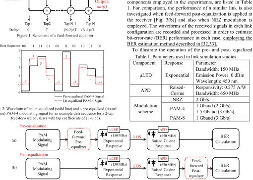
where out(t) and s(t) are the equalizer output and input signal respectively, Cn (n=1,2…N) are the tap coefficients, T is the tap delay and N is the number of taps. Fig. 1 shows the schematic of such a system while Fig. 2 shows an example of a PAM-4 waveform before and after the use of a 2-tap feed-forward equalizer. A feed-feed-forward equalizer can be easily implemented with simple electronic components or a transversal filter [30, 31]. High-speed transversal filters with adjustable tap coefficients have already been developed [30]. For VLC systems, owing to the use of moderate symbol rates (in comparison to laser-based optical links), the electronic implementation of such equalizer circuits becomes straightforward. In this work, we propose the use of a FF equalizer at the transmitter side of the link with a small number of taps (2 to 5) and a tap delay T that matches the symbol period.
C. Simulation studies
Fig. 3 shows the basic link model used in the simulation studies. The performance of the free-space LOS VLC link is evaluated when a few-tap feed-forward pre-equalizer and PAM schemes are applied [Fig 3(a)]. As indicated above, the key parameters of link components, matching the values of the components employed in the experiments, are listed in Table 1. For comparison, the performance of a similar link is also investigated when feed-forward post-equalization is applied at the receiver [Fig. 3(b)] and also when NRZ modulation is employed. The waveforms of the received signals in each link configuration are recorded and processed in order to estimate bit-error-rate (BER) performance in each case, employing the BER estimation method described in [32,33].
To illustrate the operation of the pre- and post- equalized
Fig. 3: Schematic of the (a) pre-equalized and (b) post-equalized free-space VLC system using PAM-4 modulation.
BER Calculation
PAM Modulating
Signal Exponential Response
(150 MHz)
Raised Cosine Response
(650 MHz)
Feed-forward
Pre-equalizer
APD μLED
LOS Pre-equalization
BER Calculation
PAM Modulating
Signal Exponential Response
(150 MHz)
Raised Cosine Response
(650 MHz) forward
Feed- Post-equalizer
APD μLED
LOS Post-equalization
(a)
[image:3.612.57.567.366.730.2](b)
Figure 1: Schematic of a feed-forward equalizer.
Fig. 2: Waveform of an un-equalized (solid line) and a pre-equalized (dotted line) PAM-4 modulating signal for an example data sequence for a 2-tap
feed-forward equalizer with tap coefficients of (1 -0.55).
C1 C2
T
CN-1
T
CN
T …
Tap1 Tap2 Tap N-1 Tap N Delay: 0 T (N-2) T (N-1) T
Input: s(t)
+ + +
Output: out(t)
… delay
Tap coefficients:
delay delay
-5 -3 -1 1 3 5
Pre-equalized PAM-4 Signal Un-equalized PAM-4 Signal -3
3
3
-1
-3 -3 -1 -3
3
1
11 11 01 00 11 00 10 01 00
VLC links, Fig.4 shows the simulated eye diagrams generated at each stage of the link for both configurations when the same feed-forward equalizer is used. The VLC link is assumed to operate at 1.6 Gb/s using 0.8 Gbaud PAM-4 modulation. It employs a 2-tap feed-forward pre- or post- equalizer [Fig. 4(a)]. For the post-equalized link, an un-distorted PAM-4 signal [Fig. 4(b)] modulates the LED, while the eye diagram of the detected signal at the APD is completely closed due to ISI [Fig. 4(c)]. Using the 2-tap feed-forward post-equalizer, the ISI is removed yielding open eye diagrams [Fig. 4(d)] and therefore the transmitted data can be successfully recovered at the receiver. For the pre-equalized link, the PAM-4 modulating signal is pre-distorted using the same FFE equalizer at the transmitter side of the link and is used to drive the LED [Fig. 4(e)]. The optimum coefficients of the equalizers are determined using the minimum-mean-square-error (MMSE) adaption algorithm [34]. The eye diagram of the signal at the APD is shown in Fig. 4(f). The received eye-diagram is open with 4 clear distinguishable levels indicating that the transmitted data can be detected directly without any further equalization. The BER performance of each link can be estimated by analysing the received waveforms and taking into account the noise at the receiver.
Fig. 4: (a) Tap-coefficients of the feed-forward equalizer; simulated eye-diagram of (b) ideal PAM-4 signal, (c) APD detected signal before post-equalization, (d) post-equalized PAM-4 signal, (e) pre-equalized PAM-4
signal and (f) received PAM-4 signal using pre-equalization.
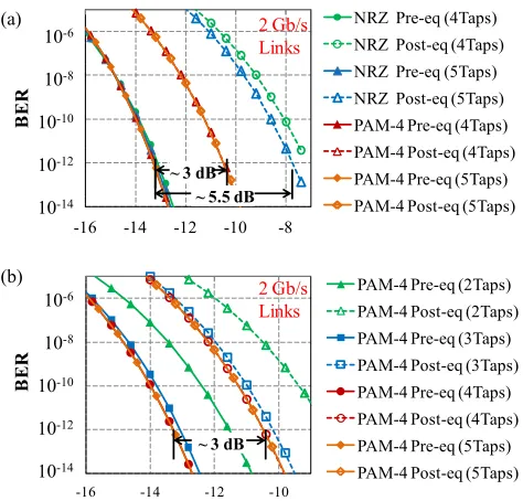
Simulations for the free-space VLC link are carried out for 2 Gb/s transmission using NRZ and PAM-4 modulation, whilst varying the number of FFE taps from 2 to 5 and the BER performance of each link configuration is obtained (Fig. 5). These results are obtained using optimized tap coefficients for each link. For NRZ based links, the feed-forward equalizers require at least 4 taps to recover the transmitted signal at 2 Gb/s; while simple 2-tap equalizers can be used for the PAM-4 based links. Similar BER performance can be achieved for both NRZ and PAM-4 links using equalization. The simulation results demonstrate that pre-equalization outperforms post-pre-equalization for all the VLC links studied. 3 dB and 5.5 dB improvements in receiver sensitivity are obtained for the 2 Gb/s PAM-4 and NRZ links respectively. This is due to the noise enhancement penalty induced in the link by the post-equalization process, as the feed-forward post-equalizer amplifies both the received signal and the noise, resulting in a degradation of the signal-to-noise ratio (SNR) at the receiver. Such a noise enhancement penalty does not exist in the pre-equalized link as the feed-forward equalizer is implemented at the transmitter side of the link. For
NRZ based links, the receiver sensitivity is 2.5 dB larger compared with the PAM-4 based links as the equalizers have larger tap coefficients to remove more ISI, resulting in a larger noise enhancement penalty for the post-equalized link.
Further simulations are carried out on the free-space VLC link comparing the performance of a 1.5 Gbaud PAM-4 and 1 Gbaud PAM-8 transmission, which both provide the same 3 Gb/s data rate. NRZ modulation would not be able to support such high data rate transmission even with a larger number of equalization taps. 3 to 5 taps are considered for the PAM-4 and PAM-8 based links due to the increased symbol rate. Again the BER performance of both the pre- and post-equalized links is extracted and compared (Fig. 6). The BER results indicate a 5 dB improved receiver sensitivity for the pre-equalized link over the respective post-equalized link. Moreover, it is found that PAM-4 modulation outperforms PAM-8 and that error-free (BER<10-12) 3 Gb/s transmission can be achieved with a 3-tap and 5-tap FFE pre-equalizer with a receiver sensitivity of -9.4 and -11.8 dBm respectively. The improved performance of PAM-4 over PAM-8 modulation for these links is explained by the increased multi-level penalty that PAM-8 exhibits.
The simulated receiver sensitivity for a 10-12 BER for the pre-equalized VLC link as a function of the number of taps is 1.25 ns 1.25 ns
1.25 ns
Tap-1 Tap-2 -1
0
1 1
-0.45 1.6 Gb/s
(c)
(f) (b)
(e) (a)
(d)
Fig. 5: Simulated BER performance of (a) NRZ and PAM-4 VLC links and (b) PAM-4-based VLC links at 2 Gb/s using pre- and post-equalization with
varying number of taps. -16 -14 -12 -10
PAM-4 Pre-eq (2Taps) PAM-4 Post-eq (2Taps) PAM-4 Pre-eq (3Taps) PAM-4 Post-eq (3Taps) PAM-4 Pre-eq (4Taps) PAM-4 Post-eq (4Taps) PAM-4 Pre-eq (5Taps) PAM-4 Post-eq (5Taps)
2 Gb/s Links
10-6
10-8
10-10
10-12
10-14
B
ER
~ 3 dB 2 Gb/s Links
10-6
10-8
10-10
10-12
10-14
B
ER
-16 -14 -12 -10 -8
NRZ Pre-eq (4Taps) NRZ Post-eq (4Taps) NRZ Pre-eq (5Taps) NRZ Post-eq (5Taps) PAM-4 Pre-eq (4Taps) PAM-4 Post-eq (4Taps) PAM-4 Pre-eq (5Taps) PAM-4 Post-eq (5Taps)
~ 3 dB ~ 5.5 dB
(a)
[image:4.612.319.556.54.281.2](b)
Fig. 6: Simulated BER performance of 3 Gb/s VLC links for different PAM schemes using pre-/ post-equalization with varying number of taps.
-14 -12 -10 -8 -6 -4
Average Received Optical Power (dBm)
PAM-8 Pre-eq (5Taps) PAM-8 Post-eq (5Taps) PAM-8 Pre-eq (3Taps) PAM-8 Post-eq (3Taps) PAM-4 Pre-eq (5Taps) PAM-4 Post-eq (5Taps) PAM-4 Pre-eq (3Taps) PAM-4 Post-eq (3Taps)
3 Gb/s Links
10-6
10-8
10-10
10-12
10-14
B
ER
~ 5 dB
[image:4.612.53.295.332.436.2]found for the different modulation schemes (NRZ, PAM-4 and PAM-8) and data rates (1.6 to 3 Gb/s) and is shown in Fig. 7. An improvement in the receiver sensitivity (up to 2 dB) can be achieved with a larger number of pre-equalizer taps. However, it can be noticed that beyond a certain number of taps no further improvement is achieved. Higher symbol rates require a larger number of the equalization taps as larger ISI occurs in the link. As a result, a PAM scheme would require fewer tap than the equivalent NRZ link due to the lower required symbol rate. The simulation results indicate that for a particular link the optimum modulation and number of taps can be selected.
In this work, a 29-1 PRBS is used to generate the PAM-4 modulation signal. In order to assess the link performance for a longer pattern which would generate more transitions, the use of a longer 215-1 PRBS pattern is also studied with the same link model. The simulated received eye diagram for a 215-1 PRBS and for a 2 Gb/s PAM-4 based VLC link using a 4 tap equalizer is shown in Fig. 8(a). The simulated received eye diagram for a 29-1 PRBS pattern is also illustrated for comparison [Fig. 8(b)]. The obtained BER performance for the two PRBS with different lengths (29-1 and 215-1) are compared in Fig. 8(c) and it is shown that a small power penalty < 0.5 dB is induced for a BER of 10-12. The use of the 29-1 PRBS pattern in the experiments therefore is not expected to result in a significant difference in obtained link performance.
III. EXPERIMENTAL RESULTS
Fig. 9 shows the experimental setup used for the data transmission experiments on the pre-equalized free-space LOS VLC link. An arbitrary waveform generator (AWG) is used to generate the PAM modulating signals and implement the feed-forward pre-equalizer at the transmitted side using its built-in functions. The generated PAM signal is amplified to appropriate voltage levels via an RF amplifier (SHF-826H) and modulates a square 20 20 μm2 450 nm μLED. The μLED is biased at a DC voltage of 5 V while the modulating signal has a 2 V peak-to-peak amplitude. The optical output is collected using an aspheric lens (Edmund #87-161) with a numerical aperture (NA) of 0.64. At the receiver side, an aspheric lens (Edmund #66-013) is used as a light concentrator focusing the light onto the APD receiver (First Sensor AD800-11). The received electrical signal is amplified using a low noise amplifier (LNA, ZFL-1000LN+) and the obtained waveforms and eye diagrams are captured using a digital storage oscilloscope. The BER performance of the link is calculated offline based on the captured waveforms and the measured receiver noise characteristics. It should be noted that the free-space distance used in the data transmission experiments is 0.6 m and is limited by the size of the optical bench. Transmission over larger distances of ~5 m is feasible as the output beam has a small divergence. In real applications, the maximum free-space distance over which the VLC link will be operated successfully depends on the required coverage, field-of-view and LED output power.
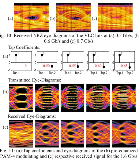
The VLC link is initially tested using a NRZ modulating signal. Fig. 10 shows the received eye diagrams at the data rates of 0.5 Gb/s, 0.6 Gb/s and 0.7 Gb/s with a received optical power of -14.2 dBm. The obtained eye diagram at 0.5 Gb/s is open (Fig 10a), albeit with a very large ISI, while the received eye diagram at 0.7 Gb/s is closed due to the limited μLED bandwidth. As expected, NRZ modulation cannot support data rates > 1 Gb/s over the VLC link. In order to achieve this, a 2-tap FFE pre-equalizer is implemented at the transmitter. The μLED is modulated by the pre-equalized PAM-4 signal at 0.8 Gbaud, providing a data rate of 1.6 Gb/s. Fig. 11 shows the eye diagram of the PAM-4 signal at the transmitter and receiver side of the link for different values of the 2nd tap coefficient with a received optical power of -14.2 dBm [Fig. 11(a)]. Fig. 11(b) shows the corresponding pre-equalized PAM-4 modulating signals while Fig. 11(c) are the respective eye diagrams recorded at the receiver. The eye diagrams obtained for an un-equalized PAM-4 modulating signal are also illustrated for comparison.
[image:5.612.58.277.187.288.2]As expected, the uncompensated PAM-4 VLC link fails; the received eye diagram is completely closed and therefore the transmitted data cannot be directly recovered at the receiver. Fig 8: Simulation results of (a) received eye-diagram using a 215-1 PRBS;
(b) received eye-diagram using 29-1 PRBS and (c) BER results for a 2 Gb/s PAM-4 based VLC link using 4 taps using a 29-1 and 215-1 PRBS.
(a) (b)
(c)
-16 -14 -12 -10
PRBS 9 Pre-eq PRBS 9 Post-eq PRBS 15 Pre-eq PRBS 15 Post-eq 10-6
10-8 10-10 10-12 10-14
BER
Average Received Optical Power (dBm)
[image:5.612.49.291.385.630.2]2 Gb/s PAM-4 4 Taps
Fig. 7: The receiver sensitivity versus the number of taps of the feed forward equalizer for various modulation schemes.
-18 -16 -14 -12 -10 -8 -6 -4
2 3 4 5 6
R
ec
ei
ve
r
S
en
si
ti
vi
ty
@
BER
=1
0
-12
(d
Bm
)
Number of Taps
1.6 Gb/s (1.6 GBaud) NRZ
1.6 Gb/s (0.8 Gbaud) PAM-4
2 Gb/s (2 Gbaud) NRZ
2 Gb/s (1 Gbaud) PAM-4
3 Gb/s (1.5 Gbaud) PAM-4
3 Gb/s (1 Gbaud) PAM-8
NRZ
1.6 Gb/s (1.6 Gbaud)
PAM-4
1.6 Gb/s (0.8 Gbaud)
NRZ
2 Gb/s (2 Gbaud)
PAM-4
2 Gb/s (1 Gbaud)
PAM-4
3 Gb/s (1.5 Gbaud)
PAM-8
3 Gb/s (1 Gbaud)
Fig. 9: Experimental setup of the free-space VLC using pre-equalization
AMP
μLED APD
Real-time Scope (BER Calculation) LNA
Pre-equalized PAM-4 Signal
AWG
0.6 mConcentrator
[image:5.612.53.281.501.639.2] [image:5.612.75.552.679.723.2]On the other hand, the received eye diagrams for the pre-equalized 1.6 Gb/s PAM-4 links are open and the 4 signal levels are clearly distinguishable. As a result, the transmitted data can be recovered directly at the receiver without any further signal processing. The BER performance of the each pre-equalized 1.6 Gb/s link is calculated for the different tap coefficients studied and the results are shown in Fig. 12. Based on the obtained BER performance, the optimum value and tolerance for the second tap coefficient in this link are obtained. Fig. 13 shows the receiver sensitivity for a 10-12 BER as a function of the value of the second tap coefficient as obtained from the simulations and experiments. For a particular target receiver sensitivity, the range of values satisfying this requirement can be identified. For example if a receiver sensitivity of -13 dBm is required in the link, a large tolerance is obtained, with suitable values within the range [-0.65 -0.5] for the experiment and [-0.6 -0.38] for the simulation. The experimental results follow the same trend as the simulation results but with a small shift in values. This difference can be attributed to the slightly different values for link bandwidth between the real link and simulation model and that non-linearities which are not taken into account in the simulation (such as the APD non-linearity). The tap coefficients of [1 -0.55] provide the best BER performance and the corresponding receiver sensitivity for a BER<10-12 is found to be -15 dBm. In practice, the optimum equalizer coefficients can be determined experimentally using a training sequence and a feedback mechanism. Communications in VLC systems are expected to be bi-directional so the real-world implementation of such equalization schemes can be incorporated in the higher-level communication protocols.
A 2 Gb/s PAM-4 free-space VLC link is also implemented using the same experimental setup and a 3-tap feed-forward pre-equalizer. The optimum tap coefficients are adaptively adjusted so as to maximize the eye opening of the received
PAM-4 signal and optimize the link BER performance. Fig. 14 shows the optimized tap coefficients [Fig. 14(a)], the corresponding eye diagrams of the pre-equalized PAM-4 modulating signal [Fig. 14(b)] and the received signal with a received optical power of -14.2 dBm [Fig. 14(c)]. It can be noticed that the eye diagram of the received PAM-4 signal is open and that the 4 signal levels are clearly distinguishable. The estimated BER performance of the link is shown in Fig. 14(d) along with the respective simulated BER performance. Error-free (BER<10-12) 2 Gb/s transmission is achieved for an average received optical power larger than -12.2 dBm, while good agreement is obtained again between experimental and simulation results.
IV. CONCLUSIONS
Feed-forward pre-equalization is proposed for use in wireless VLC systems in conjunction with PAM modulation schemes in order to overcome the limited bandwidth of LEDs and achieve multi-gigabit (> 1 Gb/s) transmission using low-complexity electronic circuitry. The proposed VLC links are based on the deployment of few-tap simple feed-forward equalizers, µLEDs, APD receivers and low-order PAM schemes. Both simulation studies and experimental results
Fig. 14: (a) Optimized tap coefficients of the 3-tap FF pre-equalizer, eye-diagram of (b) the pre-equalized and (c) received PAM-4 signal; (d)
BER plots for the optimized 2 Gb/s PAM-4 free-space VLC link.
Tap-1Tap-2Tap-3 -1
0 1
(b) (c)
(a)
1 -0.55 -0.08
(d)
10-8
10-12
10-16
10-20
B
E
R
10-4
1E-20 1E-16 1E-12 1E-08 1E-04
-16 -15 -14 -13 -12 -11
B
E
R
Average Received Optical Power (dBm)
2.0 Gb/s [1 -0.55 -0.08]
Simulation 2Gb/s Fig. 10: Received NRZ eye-diagrams of the VLC link at (a) 0.5 Gb/s, (b)
0.6 Gb/s and (c) 0.7 Gb/s
Fig. 11: (a) Tap coefficients and eye-diagrams of the (b) pre-equalized PAM-4 modulating and (c) respective received signal for the 1.6 Gb/s
VLC link.
(a) (b) (c)
Transmitted Eye-Diagrams:
(b)
Received Eye-Diagrams:
(c)
Tap-1 -1
0 1
Tap-1 Tap-2 -1
0 1
Tap-1 Tap-2 -1
0 1
Tap-1 Tap-2 -1
0 1
Tap-1 Tap-2 -1
0 1
1
-0.50
1
-0.55
1
-0.60
1
-0.65 1
Tap Coefficients:
(a)
0 Fig. 12: BER plots for the 1.6 Gb/s pre-equalized PAM-4 link over 0.6 m
[image:6.612.55.282.45.307.2]for various tap coefficients.
Fig. 13: The receiver sensitivity versus the second tap coefficient for the 1.6 Gb/s PAM-4 VLC link using a 2-tap pre-equalizer.
B
E
R
10-8
10-12
10-16
10-20
10-4
1.0E-20 1.0E-16 1.0E-12 1.0E-08 1.0E-04
-16 -15 -14 -13 -12 -11
B
E
R
[image:6.612.321.550.45.256.2] [image:6.612.328.546.439.585.2]Average Received Optical Power (dBm)
[1 -0.45] [1 -0.5] [1 -0.55] [1 -0.6] [1 -0.65] Simulation
-20 -15 -10 -5 0
-0.7 -0.6 -0.5 -0.4 -0.3
R
ec
ei
ver
S
en
si
ti
vi
ty
@
B
E
R
=
10
-12
(d
B
m
)
Second Tap Coefficient
Series1
2 Simulation
Experiment Tolerance
demonstrate that such schemes can effectively remove the ISI caused by the limited bandwidth of the link without using any complex digital signal processing. The simulation results indicate 3 Gb/s PAM-4 VLC links are feasible using on 3 to 5 taps in the equalizer and further show that improved receiver sensitivities of up to 5 dB can be achieved by employing pre-equalization over post-pre-equalization. Error-free (BER<10-12) 1.6 Gb/s and 2 Gb/s PAM-4 data transmission are achieved over a free-space VLC link using a 2-tap and 3-tap feed-forward pre-equalizer respectively, a 450 nm μLED transmitter and a Si APD receiver. The results showcase the potential benefits of pre-equalization in high-speed VLC systems, providing a cost-effective, energy-efficient and low-complexity approach to overcome the bandwidth limitation.
REFERENCES
[1] T. Komine and M. Nakagawa, "Fundamental analysis for visible-light communication system using LED lights," IEEE Trans. Consum. Electron., vol.50, no.1, pp.100-107, Feb. 2004
[2] A. Jovicic, J. Li, T. Richardson, "Visible light communication: opportuneties, challenges and the path to market," IEEE Commun. Mag., vol. 51, no.12, pp.26, Dec. 2013.
[3] H. Elgala, R. Mesleh, H. Haas, "Indoor optical wireless communication: potential and state-of-the-art," IEEE Commun. Mag., vol.49, no.9, pp.56-62, Sept. 2011
[4] J.M. Kahn, J.R. Barry, "Wireless infrared communications," Proc. IEEE, vol.85, no.2, pp.265-298, Feb. 1997
[5] C.Y. Ying, C.Y. Li, H.H. Lu, C.H. Chang, J.H. Chen, and J.R. Zheng, "A Hybrid WDM Lightwave Transport System Based on Fiber-Wireless and Fiber-VLLC Convergences," IEEE Photon. J, vol.6, no.6, pp.1-9, Dec. 2014
[6] C. Cheng, M. Ijaz, D. Tsonev, H. Haas, "Analysis of downlink transmission in DCO-OFDM-based optical attocell networks," in 2014 IEEE Global Communications Conference, pp.2072-2077, Dec. 2014 [7] C.G. Xi, A. Mirvakili, V.J. Koomson, "A Visible Light Communication
System Demonstration Based on 16-Level Pulse Amplitude Modulation of an LED Array," in 2012 Symposium on Photonics and Optoelectronics (SOPO), pp.1-4, May 2012
[8] D. Tsonev, H.C. Chun, S. Rajbhandari, J.J.D. McKendry, S. Videv, E. Gu, M. Haji, S. Watson, A.E. Kelly, G. Faulkner, M.D. Dawson, H. Haas, D. O'Brien, "A 3-Gb/s Single-LED OFDM-Based Wireless VLC Link Using a Gallium Nitride μLED," IEEE Photon. Technol. Lett. vol.26, no.7, pp.637-640, Apr. 2014
[9] F.M. Wu, C.T. Lin, C.C. Wei, C.W. Chen, Z.Y. Chen, H.T. Huang, C. Sien, "Performance Comparison of OFDM Signal and CAP Signal Over High Capacity RGB-LED-Based WDM Visible Light Communication," IEEE Photon. J., vol.5, no.4, pp.7901507-7901507, Aug. 2013
[10] Y.G. Wang, L. Tao, X.X. Huang, J.Y. Shi, N. Chi, "Enhanced Performance of a High-Speed WDM CAP64 VLC System Employing Volterra Series-Based Nonlinear Equalizer," IEEE Photon. J., vol.7, no.3, pp.1-7, June 2015
[11] D.J.F. Barros, S.K. Wilson, J.M. Kahn, "Comparison of Orthogonal Frequency-Division Multiplexing and Pulse-Amplitude Modulation in Indoor Optical Wireless Links," IEEE Trans. Commun., vol.60, no.1, pp.153-163, Jan. 2012
[12] X. Li; N. Bamiedakis, J.L. Wei, J.J.D. McKendry, E.Y. Xie, R. Ferreira, E. Gu, M.D. Dawson, R.V. Penty, I.H. White, "μLED-Based Single-Wavelength Bi-directional POF Link with 10 Gb/s Aggregate Data Rate," J. Lightw. Technol., vol.33, no.17, pp.3571-3576, Sept. 2015. [13] A.H. Azhar, T.A. Tran, D. O'Brien, "Demonstration of high-speed data
transmission using MIMO-OFDM visible light communications," in 2010 IEEE GLOBECOM Workshops (GC Wkshps), pp.1052-1056, Dec. 2010
[14] S. Rajbhandari, H. Chun; G. Faulkner, K. Cameron, A.V.N. Jalajakumari, R. Henderson, D. Tsonev, M. Ijaz, Z. Chen, H. Haas, E. Xie, J.J.D. McKendry, J. Herrnsdorf, E. Gu, M.D. Dawson, D. O'Brien, "Imaging-MIMO visible light communication system using μLEDs and integrated receiver," in Globecom Workshops (GC Wkshps), pp.536-540, Dec. 2014
[15] F.M. Wu, C.T. Lin, C.C. Wei, C.W. Chen, Z Y. Chen, H.T. Huang, "3.22-Gb/s WDM visible light communication of a single RGB LED employing carrier-less amplitude and phase modulation," in Optical Fiber Communication Conference and Exposition and the National Fiber Optic Engineers Conference (OFC/NFOEC), pp.1-3, Mar. 2013 [16] R. Mesleh, H. Elgala, H. Haas, "Optical Spatial Modulation," IEEE J.
Opt. Commun. Netw., vol.3, no.3, pp.234-244, Mar. 2011
[17] M. Ijaz, D. Tsonev, J.J.D. McKendry, E. Xie, S. Rajbhandari, H. Chun, G. Faulkner, E. Gu, M.D. Dawson, D. O'Brien, H. Haas, "Experimental proof-of-concept of optical spatial modulation OFDM using micro LEDs," in 2015 IEEE International Conference on Communication Workshop (ICCW), pp.1338-1343, June 2015
[18] H. Le Minh, D. O'Brien, G. Faulkner, L. Zeng, K. Lee, D. Jung; Y. Oh, "80 Mbit/s Visible Light Communications using pre-equalized white LED," in 34th European Conference on Optical Communication, pp.1-2, Sept. 2008
[19] H.L. Li, X.B. Chen, B.J. Huang, D.Y. Tang, H.D. Chen, "High Bandwidth Visible Light Communications Based on a Post-Equalization Circuit," IEEE Photon. Technol. Lett., vol.26, no.2, pp.119-122, Jan. 2014
[20] T. Komine, J.H. Lee, S. Haruyama, M. Nakagawa, "Adaptive equalization system for visible light wireless communication utilizing multiple white LED lighting equipment," IEEE Trans. Wireless Commun., vol.8, no.6, pp.2892-2900, June 2009
[21] B. L. Kasper, "Equalization of multimode optical fiber systems," Bell Syst. Tech. J, vol.61, no.7, pp.1367-1388, Sept. 1982
[22] K. Azadet, E.F. Haratsch, H. Kim, F. Saibi, J.H. Saunders, M. Shaffer, L.L. Song, M.L. Yu, "Equalization and FEC techniques for optical transceivers," IEEE J. Solid-State Circuits, vol.37, no.3, pp.317-327, Mar. 2002
[23] M. Maeng, F. Bien, Y. Hur, H. Kim, S. Chandramouli, E. Gebara, and J. Laskar, "0.18-μm CMOS equalization techniques for 10-Gb/s fiber optical communication links," in Microwave Theory and Techniques, IEEE Transactions on , vol.53, no.11, pp.3509-3519, Nov. 2005 [24] D.M. Kuchta, A.V. Rylyakov, C.L. Schow, J.E. Proesel, C. Baks, C.
Kocot, L. Graham, R. Johnson, G. Landry, E. Shaw, A. MacInnes, J. Tatum, "A 55Gb/s directly modulated 850nm VCSEL-based optical link," in Photonics Conference (IPC), pp.1-2, Sept. 2012
[25] J.J.D. McKendry, D. Massoubre, S. Zhang, B.R. Rae, R.P. Green, E. Gu, R.K. Henderson, A.E. Kelly, M.D. Dawson, "Visible-Light Communications Using a CMOS-Controlled Micro-Light- Emitting-Diode Array," J. Lightw. Technol., vol.30, no.1, pp.61,67, Jan., 2012 [26] J.J.D. McKendry, R.P. Green, A.E. Kelly, G. Zheng, B. Guilhabert, D.
Massoubre, E. Gu, M.D. Dawson, "High-Speed Visible Light Communications Using Individual Pixels in a Micro Light-Emitting Diode Array," IEEE Photon. Technol. Lett., vol.22, no.18, pp.1346-1348, Sept. 2010
[27] X. Li, J.L. Wei, N. Bamiedakis, R.V. Penty, I.H. White, “Avalanche photodiode enhanced PAM-32 5 Gb/s LED-POF link,” in European Conference on Optical Communication (ECOC), pp.1-3, Sept. 2014; [28] K.Y. Cui, G. Chen, Z.Y. Xu, R.D. Roberts, "Line-of-sight visible light
communication system design and demonstration," in International Symposium on Communication Systems Networks and Digital Signal Processing (CSNDSP), pp.621-625, July 2010
[29] T.S. Rappaport, Wireless Communications: Principles and Practice, 2nd, Prentice Hall PTR (2002).
[30] H. Wu, J.A. Tierno, P. Pepeljugoski, J. Schaub, S. Gowda, J.A. Kash, A. Hajimiri, "Integrated transversal equalizers in high-speed fiber-optic systems," IEEE J. Solid-State Circuits, vol.38, no.12, pp.2131-2137, Dec. 2003
[31] J. Sewter, A.C. Carusone, "A 40 Gb/s transversal filter in 0.18 /spl mu/m CMOS using distributed amplifiers," in IEEE Custom Integrated Circuits Conference, pp.417-420, Sept. 2005
[32] J.G. Proakis and M. Salehi, "Digital Communications, Fifth Edition", McGraw Hill, 2008.
[33] K. Szczerba, P. Westbergh, J. Karout, J.S. Gustavsson, A. Haglund, M. Karlsson, P.A. Andrekson, E. Agrell, A. Larsson, "4-PAM for high-speed short-range optical communications," in IEEE J. Opt. Commun. Netw., vol.4, no.11, pp.885-894, Nov. 2012