RESEARCH PAPER
Optimising electrogenerated chemiluminescence of quantum dots
via co-reactant selection
Rebekah Russell1&Alasdair J. Stewart1&Lynn Dennany1
Received: 22 February 2016 / Revised: 24 March 2016 / Accepted: 8 April 2016 #The Author(s) 2016. This article is published with open access at Springerlink.com
Abstract We demonstrate that for quantum dot (QD) based electrochemiluminescence (ECL), the commonly used co-reactant does not perform as effectively as potassium persul-fate. By exploiting this small change in co-reactant, ECL in-tensity can be enhanced dramatically in a cathodic-based ECL system. However, TPA remains the preferential co-reactant-based system for anodic ECL. This phenomenon can be rationalised through the relative energy-level profiles of the QD to the co-reactant in conjunction with the applied potential range. This work highlights the importance of understanding the co-reactant pathway for optimising the application of ECL to bioanalytical analysis, in particular for near-infrared (NIR) QDs which can be utilised for analysis in blood.
Keywords Electroanalytical methods . Electrochemiluminescence . Quantum dots
Introduction
The application of electrochemiluminescence (ECL) in re-search and commercial applications has been predominantly focused on ruthenium complexes that displayed intense, stable signals in both organic and aqueous media [1–4]. The vast
majority of these systems are based upon the classic [Ru(bpy)3]2+-tri-n-propylamine (TPA) co-reactant system, and the development of new luminophores and alternative co-reactants have attracted much attention. Following the dis-covery of ECL emission from silicon quantum dots (QDs) [5], the focus of investigations shifted towards nanomaterials that displayed size-tunable emission and enhanced optical and electronic properties [6]. The vast majority of these works focused on materials that emitted in the visible region, resulting in a good understanding of the ECL behaviour of these materials.
The ECL of visible region QDs has been studied extensive-ly, which has been shown to produce an ECL response with a variety of co-reactants [7–10]. This has allowed the develop-ment of a number of ECL biosensors that use visible region QDs as labels [11–14]. Near-infrared (NIR) QDs are of in-creasing interest owing to their emission wavelength that lies outside the absorption range of biological fluids and tissue. The potential benefits of NIR-emitting species in biosensing and imaging applications have been well documented because of their improved penetrability through biological samples and reduced tissue autofluorescence [15,16]. This can provide more detailed and better-defined images for deep tissue imag-ing. For biosensing, it opens up opportunities for development of systems with detection directly from whole blood samples, negating the requirement for time-consuming and expensive sample preparation procedures.
Currently, no such investigations into the behaviour of NIR QDs in different systems have been carried out, with the ma-jority of work focused on cathodic NIR ECL with potassium persulfate co-reactant [17–19]. Only a single example exists of anodic NIR ECL [20–22], and there are currently no docu-mented ECL systems that utilise NIR-emitting QDs and no additional co-reactant (termed co-reactant-free systems). Therefore, the ECL characteristics of these QDs have not been Published in the topical collectionAnalytical Electrochemiluminescence
with guest editors Hua Cui, Francesco Paolucci, Neso Sojic, and Guobao Xu.
* Lynn Dennany
1 Department of Pure and Applied Chemistry, Technology and
Innovation Centre, University of Strathclyde, 99 George Street, Glasgow G1 1RD, UK
determined in a variety of systems, which has prevented a full understanding of their ECL behaviour. Investigation into these properties should supplement the electrochemical characteri-sation of these QDs and could aid in the development of a greater variety of NIR ECL biosensors.
NIR-emitting QDs are beginning to emerge as leaders in this field as a result of their excellent optical properties, large surface-to-volume ratio and surface modification opportuni-ties [23]. They have successfully been used within in vivo imaging studies [24–28]; however, there has been limited work on their application within ECL biosensing platforms [19,20]. This has recently been shown for the determination of dopamine in whole blood, highlighting the significance of NIR QDs for biosensing [21]. This research demonstrates the flexibility of NIR QDs, which can generate an ECL signal with a variety of co-reactant systems. Therefore, the develop-ment was the optimisation of these conditions to obtain the most sensitive, responsive and stable ECL signal. This has not been done previously with NIR QDs, and thus there is a clear requirement for such investigations.
The aims of this work were to investigate the ECL charac-teristics of NIR QDs in a variety of co-reactant systems and determine the likely mechanisms of their response and to de-termine the optimal co-reactant for a defined application. Although this work is specific to NIR QD ECL, the insights found can be applied to any QD ECL-based system.
Experimental
Apparatus
Electrochemical measurements were carried out using a CH instrument model 760D electrochemical analyser. All experi-ments were carried out using a conventional three-electrode assembly, consisting of a 3 mm diameter GC working elec-trode (unless otherwise stated), Pt wire counter elecelec-trode and Ag/AgCl reference electrode. Working electrodes were cleaned by successive polishing using 1, 0.3 and 0.05μM alumina slurry, followed by sonication in ethanol and water, respectively, for 30 min. The electrodes were then dried under a flow of N2gas. Cyclic voltammetry (CV) was carried out at a scan rate of 100 mV s−1and sample interval of 1 mVacross a potential range outlined in each figure. Measurements involv-ing simultaneous detection of light and current utilised a CH instrument model 760D connected to a Hamamatsu H10723-20 PMT. The input voltage to the PMT was +5 V, and the control voltage was set between 0.5 and 1.05 V depending on the required sensitivity. The scan rate was 100 mV s−1 (unless otherwise stated). During electrochemical experi-ments, the cell was kept in a light-tight Faraday cage in a specially designed holder configuration where the working
electrode was positioned directly above the PMT window. All measurements were made at room temperature.
Materials
Core-shell CdSeTe/ZnS QDs (Qdot® 800 ITK™ organic quantum dots, 1 μM in decane) were purchased from Invitrogen. 2-(Dimethylamino)ethanthiol (DAET), Nafion® 117 solution, chitosan (medium molecular weight, 75–85 % deacetylated), phosphate-buffered saline (PBS, pH 7.4), po-tassium persulfate (K2S2O8), hydrogen peroxide (H2O2), tripropylamine (TPA), sodium oxalate (Na2C2O4), tris ace-tate–EDTA (TAE) buffer, 4-morpholineethanesulfonic acid hydrate (MES), sodium bicarbonate, sulfuric acid (H2SO4) and sodium hydroxide (NaOH) were all purchased from Sigma-Aldrich and used as received. All other reagents used were of analytical grade, and all solutions were prepared in Milli-Q water (18 mΩcm).
Methods
Preparation of water-soluble CdSeTe/ZnS core-shell QDs
The method followed was similar to that developed by Woelfle and Claus [29,30]. 0.5 mL of 0.5 M DAET in meth-anol was mixed with 0.25 mL of the CdSeTe/ZnS QDs in decane (1 μM). N2was bubbled through the solution for 5 min, which was then sealed and left stirring overnight in the dark at room temperature. The QDs were then precipitated with an excess of acetone followed by centrifugation at 5000 rpm for 6 min. The filtrate was removed and the precip-itate was re-dispersed in 0.25 mL of distilled water. These water-soluble QDs were centrifuged for a further 6 min at 3000 rpm to remove any impurities and then stored in dark-ness at 4 °C.
Preparation of CdSeTe/ZnS core-shell QD–polymer composite films
Preparation of co-reactant solutions
Co-reactant solutions of TPA, Na2C2O4, H2O2and K2S2O8 were prepared in 0.1 M PBS (pH 7.4) at the concentrations outlined in each figure.
Results and discussion
Estimation of HOMO and LUMO energy levels
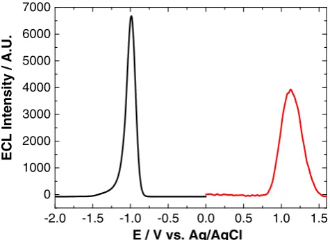
The onset of QD oxidation and reduction has previously been used to estimate the highest occupied molecular orbital (HOMO)–lowest unoccupied molecular orbital (LUMO) gap [25,31], also known as the quasi-particle gap. Often, the quasi-particle gap estimated in this way can be unreliable, as the true oxidation and reduction potentials of the QDs cannot always be detected. Therefore, it was proposed that the onset potential for ECL could be used as a more accurate estimate of these potentials, as the rate-determining step for ECL genera-tion is the oxidagenera-tion or reducgenera-tion of QDs. Figure1shows the anodic and cathodic ECL profiles of NIR QDs. The oxidative and reductive ECL onset potentials for the QDs and the HOMO–LUMO energy gap are shown in Table1.
The estimated HOMO–LUMO energy gap of 800 nm QDs (1.50 eV) is in good agreement with the opticalEgof 1.569 eV
from optically induced emission and 1.529 eV from ECL emission (see Fig.2). This confirms that ECL emission is originating from the QD core. The proposed electronic struc-ture of these NIR QDs is outlined in Fig.3. The HOMO and LUMO energy levels are calculated from the reduction and oxidation ECL onset potentials (the energy level of Ag/AgCl in a vacuum is calculated as−4.74 eV) [32,33].
HOMO energy is in excellent agreement with that obtained from differential pulse voltammetry (DPV), whilst LUMO energy is 0.70 eV less energetic when using ECL onset po-tentials. This data suggests electron injection into the 1S(e) quantum confined orbital of the NIR QDs is taking place at a more positive potential than that observed using voltam-metric techniques. The similarity between optical Eg
and the HOMO–LUMO energy gap calculated from ECL on-set potentials suggests this method of electronic structure es-timation is more accurate than that using CV or DPV.
Co-reactant assessment
In order to develop a highly sensitive ECL system, a number of co-reactants were examined to ensure maximum perfor-mance for these NIR QDs. As biomedical diagnostics contin-ually drive towards improved biosensor sensitivities, this is a key parameter in the development of any sensing system.
Anodic ECL involves an oxidative–reductive system in which a hole is injected into the 1S(h) energy level of the QD through heterogeneous electron transfer with the elec-trode. This is followed by electron injection into the 1S(e) energy level of this charged particle via homogeneous electron transfer with a co-reactant that has sufficient reducing power. Tripropylamine (TPA) and sodium oxalate (Na2C2O4) are typ-ical anodic ECL co-reactants that have been studied extensive-ly within ruthenium-containing systems [2, 3, 34–37]. However, generation of an ECL signal between these co-reactants and NIR QDs has not yet been investigated. Figure4shows the ECL profile of NIR QDs with TPA and
-2.0 -1.5 -1.0 -0.5 0.0 0.5 1.0 1.5
0 1000 2000 3000 4000 5000 6000 7000
ECL Intensit
y
/ A.U.
E / V vs. Ag/AgCl
Fig. 1 ECL response of an 800 nm QD/chitosan film in 1 mM TPA (red) and 1 mM K2S2O8(black) at a scan rate of 100 mV s−1over the potential
[image:3.595.306.543.93.140.2]range–2≤ν≤2 V vs. Ag/AgCl
Table 1 Reduction and oxidation ECL onset potentials and resulting HOMO–LUMO energy gap for a series of QDs in the presence of a co-reactant
QD/ nm
Reduction ECL onset/V vs. Ag/AgCl
Oxidation ECL onset/V vs. Ag/AgCl
HOMO–LUMO energy gap/eV
800 −0.75 0.75 1.50
700 800 900 1000
0 2 4 6 8
Emis
sion Intensity / A.U.
λλ / nm
[image:3.595.52.290.507.680.2] [image:3.595.331.515.553.690.2]Na2C2O4co-reactants, as well as in a solution of 0.1 M PBS (co-reactant-free system).
Cathodic ECL involves formation of ECL precursor spe-cies through reduction at the electrode surface, followed by homogenous electron transfer between these species to gener-ate an excited stgener-ate (reductive–oxidative system). For QDs, an electron is injected into the 1S(e) energy level of their conduc-tion band at a potential governed by their size. For emission of an ECL signal, hole injection into the 1S(h) orbital of this charged QD is then required, which is achieved through inter-action with a strong oxidising agent created via reduction and decomposition of a suitable reactant species. Typical co-reactant species capable of forming such reactive intermedi-ates include hydrogen peroxide (H2O2) and potassium
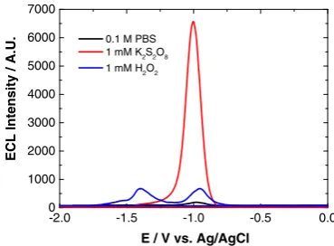
persulfate (K2S2O8) [1,18,38–43]. Figure5 shows the QD ECL profile with H2O2and K2S2O8co-reactants, and in PBS (co-reactant-free system).
Cathodic ECL was observed with K2S2O8and H2O2 co-reactants and with the co-reactant-free system. Both H2O2and 0.1 M PBS exhibit a double peak profile with the onset of reductive ECL peak 1 at−0.75 V (ECL-1) and the onset of peak 2 at−1.15 V (ECL-2). Maximum intensity of these peaks is reached at−1.00 and−1.35 V, respectively. The strongest ECL signal was obtained with K2S2O8, which displayed a single reductive ECL peak with the onset at−0.75 V and peak maximum at−1.00 V.
As mentioned, in the presence of H2O2, two ECL peaks were present, which has been observed previously [21]. The initial peak, ECL-1, was shown to result from the interaction of QDs with radical oxygen species (ROS) created following O2reduction at the electrode surface. ECL-2 is produced fol-lowing the one-electron reduction of H2O2to produce OH
· , which can then interact with QDs to generate ECL as outlined in Eqs.1–7. Previous investigations have shown that ECL-2 is more sensitive to the dissolved H2O2and thus should be cho-sen to detect H2O2for the production of ECL through the following electrochemical reactions [21]:
QDs þ 1e−→QDs eð −1SeÞ ð1Þ
H2O2þ 1e−→OH−þ OH⋅ ð2Þ
QDs eð −1SeÞ þ H2O2→QDs þ OH−þ OH⋅ ð3Þ
OH⋅þ QDs→OH−þ QDs hð þ1ShÞ ð4Þ
QDs eð −1SeÞ þ OH⋅→OH−þ QDs* ð5Þ
QDs eð −1SeÞ þ QDs hð þ1ShÞ→QDs* ð6Þ
QDs*→QDs þhνð800 nmÞ ð7Þ
This shows that a NIR QD ECL response can be generated in the presence of commonly used cathodic (K2S2O8 and H2O2) and anodic (TPA and Na2C2O4) region co-reactants, which were shown to enhance ECL intensities compared to Fig. 3 Energy level diagram for 800 nm CdSeTe/ZnS QDs based on their
reductive and oxidative ECL onset potentials and HOMO–LUMO energy gap
0.0 0.2 0.4 0.6 0.8 1.0 1.2 1.4 1.6 0
1000 2000 3000 4000 5000 6000 7000
ECL Intensity / A.U.
E / V vs. Ag/AgCl
Fig. 4 ECL response of 800 nm QD/chitosan film in 0.1 M PBS (red) + 1 mM Na2C2O4(blue) and + 1 mM TPA (black) at a scan rate of
100 mV s−1over the potential range 0.5≤ν≤1.6 V vs. Ag/AgCl
-2.0 -1.5 -1.0 -0.5 0.0 0
1000 2000 3000 4000 5000 6000 7000
ECL Intensity / A.U.
E / V vs. Ag/AgCl
0.1 M PBS 1 mM K2S2O8 1 mM H2O2
Fig. 5 ECL response of 800 nm QD/chitosan film in 0.1 M PBS (black), 1 mM H2O2(blue) and 1 mM K2S2O8(red) at a scan rate of 100 mV s−1
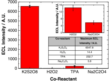
[image:4.595.75.262.57.263.2] [image:4.595.52.287.511.680.2] [image:4.595.331.516.546.682.2]co-reactant-free systems. Therefore, these co-reactants were selected for investigation with the aim of determining which system provided optimal ECL performance. A comparison of the ECL response from these co-reactants is shown in Fig.6. It is clearly evident from Fig.6that K2S2O8generates the most intense ECL response from NIR QDs that have been confined to the electrode surface. This is followed by TPA, H2O2and Na2C2O4. Figure7shows the maximum ECL in-tensity attained with each co-reactant.
This data illustrates that maximum ECL intensity was ob-tained with K2S2O8, which was over 450 times greater than with the alternative cathodic co-reactant, H2O2. It was 30 times greater than with TPA and over 1100 times greater than with Na2C2O4. With anodic co-reactants, maximum ECL in-tensity was 40 times greater in TPA compared to Na2C2O4. Figure 8 shows a clearer image of the ECL response with H2O2, TPA and Na2C2O4using more sensitive PMT settings, confirming the trend in sensitivity is TPA > H2O2> Na2C2O4. As mentioned, cathodic ECL required the formation of excited state QDs [33]; this occurs through the interaction with a suitably strong reducing agent—SO4·− and OH·— for K2S2O8 and H2O2 co-reactants, respectively. Rapid
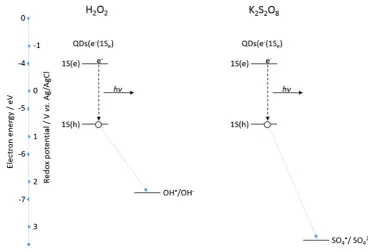
band-edge recombination of this excited state QD domi-nates over any oxidation processes, protecting destruction of the QDs following hole injection and allowing efficient ECL production [44]. The rate of this intermolecular elec-tron transfer between a negatively charged QD and the oxidising agent is a major factor in the generated ECL intensity [45]. Therefore, the strength of the oxidising agent has a critical impact on the observed ECL intensity. The standard redox potential (vs. Ag/AgCl) for the SO4·
−/SO
42−couple is approximately 3.16 V [46], whereas for the OH·/OH− couple, it is 2.16 V (vs. Ag/AgCl) at physi-ological pH [47]. Figure9 shows a comparison of the en-ergetics of these species with the QD HOMO and LUMO levels and their interactions during the ECL process.
Both oxidising species are capable of hole injection into the 1S(h) quantum confined orbital of the NIR QDs. This can be seen both in Fig.9as well as the fact that an ECL response is observed with both co-reactants. The greater oxidising strength of SO4·−compared to OH·results in a more rapid rate of QD hole injection and therefore a more rapid rate of excited state QD formation. This manifests itself as an increase in ECL intensity with the K2S2O8system. It must be noted that the double peak nature of the ECL profile in H2O2will likely influence the ECL intensity of the H2O2-sensitive peak. This is because the concentration of QDs (e−(1Se)) for interaction with OH·will have been diminished following consumption during generation of peak 1.
For anodic ECL, one factor affecting intensity is the ability of the electrogenerated co-reactant species to inject an electron into the 1S(e) energy level of oxidised QDs. Figure10shows a comparison of the energetics of these co-reactant species (TPA·and CO2·−) with the QD HOMO and LUMO levels and their interactions during the ECL process. The standard redox potential of TPA·/P, where P is the product of TPA· oxidation, is approximately−1.70 V (vs. Ag/AgCl) [2] and that of CO2·−/CO2is approximately−2.00 V (vs. Ag/AgCl) [48].
-2.0 -1.5 -1.0 -0.5 0.0 0.5 1.0 1.5 0
1000 2000 3000 4000 5000 6000 7000
ECL Intensity / A.U.
E / V vs. Ag/AgCl
Fig. 6 ECL response of 800 nm QD/chitosan film with 1 mM K2S2O8
(red), 1 mM H2O2(blue), 1 mM TPA (black) and 1 mM Na2C2O4
(purple) at a scan rate of 100 mV s−1 over the potential range
−2≤ν≤1.6 V vs. Ag/AgCl
K2S2O8 H2O2 TPA Na2C2O4 0
1000 2000 3000 4000 5000 6000 7000
H2O2 Na2C2O4
0 4 8 12 16
E
C
L I
n
tensi
ty
/
A
.U
.
ECL Intensity / A.U.
Co-Reactant
Co-reactant Maximum ECL intensity / A.U.
K2S2O8 6547.8
H2O2 14.4
TPA 232.7
Na2C2O4 5.8
Fig. 7 Maximum ECL intensity of 800 nm QD/chitosan film in a selection of co-reactant systems. Theinsetshows the lower response of H2O2and Na2C2O4for clarity with the averaged results also shown
-2.0 -1.5 -1.0 -0.5 0.0 0.5 1.0 1.5 0
1000 2000 3000 4000 5000 6000
ECL Intensity / A.U.
E / V vs. Ag/AgCl
Fig. 8 ECL response of 800 nm QD/chitosan film with 1 mM H2O2
(red), 1 mM TPA (blue) and 1 mM Na2C2O4(black) at a scan rate of
[image:5.595.332.524.50.191.2] [image:5.595.74.267.52.190.2] [image:5.595.76.265.542.681.2]The stronger reducing power of CO2·−compared to TPA· does not result in a more intense ECL signal (Fig.7), as would be expected due to faster homogenous electron transfer with QDs (h+(1Sh)). This means another factor is affecting excited state formation in this system. This is related to consumption of QDs (h+(1Sh)) during electrogeneration of CO2·−. The re-sult is that ECL intensity of the QD/TPA system is significant-ly greater, as electrogeneration of TPA·can occur directly at the electrode surface, even though homogeneous electron transfer kinetics in this system are likely slower.
These results clearly show that maximum NIR QD ECL sensitivity is achieved in the cathodic region with K2S2O8
co-reactant. Development of NIR QD ECL systems that require maximum sensitivity should therefore focus on cathodic ECL with this co-reactant. The data have also shown that H2O2and TPA are suitable co-reactants, however, a limited response with Na2C2O4suggests it is unsuitable for use in this system.
Conclusion
Significantly, this is the first detailed investigation into the optimal conditions for generation of ECL from NIR QDs based on co-reactant selection, which are likely to play a key Fig. 9 Significant energy-level
[image:6.595.172.541.50.302.2]interactions and resulting ECL process of 800 nm QDs with H2O2and K2S2O8co-reactants
[image:6.595.178.548.479.719.2]role in future development of ECL biosensors [3]. In the fu-ture, this research will aid in the selection of suitable co-reactants for achieving optimal biosensor response from these NIR QDs. The main point of significance from this research is the far superior sensitivity of K2S2O8co-reactant ECL com-pared to other common co-reactants, indicating that this should be used preferentially to obtain the most intense re-sponse. For any QD-based system, this requires consideration of the electrode platform, whether anodic or cathodic re-sponses are required, the onset and energy-level interactions resulting from the QD and co-reactant which can be based upon the data presented here. It should be noted that the ener-gy levels for the QDs are specific to their size and will impact on the selection of an appropriate co-reactant.
However, the detection of both cathodic and anodic ECL responses demonstrates the versatility of these NIR QDs, which should allow their use in a wide variety of sensing systems and to expand the application of ECL-based systems into biological samples such as blood and tissues. Overall, these investigations have outlined the best electrochemical system for generation of an intense NIR QD ECL response. This provides the framework for further NIR QD ECL biosen-sor development.
Compliance with ethical standards
Conflict of interest The authors declare that they have no conflict of interest.
Funding sources This work was supported by funding from the EU FP7 funding through the Marie Curie Reintegration Grant scheme (PIRG-2010-268236).
Open AccessThis article is distributed under the terms of the Creative Commons Attribution 4.0 International License (http:// creativecommons.org/licenses/by/4.0/), which permits unrestricted use, distribution, and reproduction in any medium, provided you give appropriate credit to the original author(s) and the source, provide a link to the Creative Commons license, and indicate if changes were made.
References
1. Choi JP, Bard AJ. Electrogenerated chemiluminescence (ECL) 79: reductive-oxidation ECL of tris(2,2′-bipyridine)ruthenium(II) using hydrogen peroxide as a coreactant in pH 7.5 phosphate buffer so-lution. Anal Chim Acta. 2005;541:141–8.
2. Miao W, Choi JP, Bard AJ. Electrogenerated chemiluminescence 69: the tris(2,2′-bipyridine)ruthenium(II), (Ru(bpy)32+)/Tri-npropylamine (TPrA) system revisited a new route involving TPrA•+ cation radicals. J Am Chem Soc. 2002;124:14478–85. 3. Kanoufi F, Bard AJ. Electrogenerated chemiluminescence. 65. An
investigation of the oxidation of oxalate by Tris(polypyridine) ru-thenium complexes and the effect of the electrochemical steps on the emission intensity. J Phys Chem B. 1999;103:10469–80. 4. McCord P, Bard AJ. Electrogenerated chemiluminescence: Part 54.
Electrogenerated chemiluminescence of ruthenium(II) 4,4′
-diphenyl-2,2′-bipyridine and ruthenium(II) 4,7-diphenyl-1,10-phenanthroline systems in aqueous and acetonitrile solutions. J Electroanal Chem Interfacial Electrochem. 1991;318:91–9. 5. Ding Z, Quinn BM, Haram SK, Pell LE, Korgel BA, Bard AJ.
Electrochemistry and electrogenerated chemiluminescence from silicon nanocrystal quantum dots. Science. 2002;296:1293–7. 6. Qi H, Peng Y, Gao Q, Zhang C. Applications of nanomaterials in
electrogenerated chemiluminescence biosensors. Sensors. 2009;9: 674–95.
7. Wang S, Harris E, Shi J, Chen A, Parajuli S, Jing X, et al. Electrogenerated chemiluminescence determination of C-reactive protein with carboxyl CdSe/ZnS core/shell quantum dots. PCCP. 2010;12:10073–80.
8. Liu PZ, Hu XW, Mao CJ, Niu HL, Song JM, Jin BK, et al. Electrochemiluminescence immunosensor based on graphene ox-ide nanosheets/polyaniline. Electrochim Acta. 2013;113:176–80. 9. Wang Y, Lu J, Tang L, Chang H, Li J. Graphene oxide amplified
electrogenerated chemiluminescence of quantum dots and Its selec-tive sensing for glutathione from thiol-containing compounds. Anal Chem. 2009;81:9710–5.
10. Wang Z, Song H, Zhao H, Li Y. Graphene-amplified electrogenerated chemiluminescence of CdTe quantum dots for H2O2sensing. Luminescence. 2013;28:259–64.
11. Yan P, Tang Q, Deng A, Li J. Ultrasensitive detection of clenbuterol by quantum dots based electrochemiluminescent immunosensor using gold nanoparticles as substrate and electron transport acceler-ator. Sensors Actuators B Chem. 2014;191:508–15.
12. Li S, Luo J, Yang X, Wan Y, Liu C. A novel immunosensor for squamous cell carcinoma antigen determination based on CdTe@Carbon dots nanocomposite electrochemiluminescence res-onance energy transfer. Sensors Actuators B Chem. 2014;197:43–9. 13. Deng S, Lei J, Huang Y, Cheng Y, Ju H. Electrochemiluminescent quenching of quantum dots for ultrasensitive Immunoassay through oxygen reduction catalyzed by nitrogen-doped graphene-supported Hemin. Anal Chem. 2013;85:5390–6.
14. Fei W, Chen F, Sun L, Li Q, Yang J, Wu Y. Ultrasensitive electrochemiluminescent immunoassay for morphine using a gold electrode modified with CdS quantum dots, polyamidoamine, and gold nanoparticles. Microchim Acta. 2014;181:419–25.
15. Frangioni JV. In vivo near-infrared fluorescence imaging. Curr Opin Chem Biol. 2003;7:626–34.
16. Wang J, Han H. Near-infrared electrogenerated chemiluminescence from quantum dots. Rev Anal Chem. 2013;32:91–101.
17. Liang GX, Li LL, Liu HY, Zhang JR, Burda C, Zhu JJ. Fabrication of near-infrared-emitting CdSeTe/ZnS core/shell quantum dots and their electrogenerated chemiluminescence. Chem Commun. 2010;46:2974–6.
18. Cui R, Gu YP, Bao L, Zhao JY, Qi BP, Zhang ZL, et al. Near-infrared electrogenerated chemiluminescence of ultrasmall Ag2Se quantum
dots for the detection of dopamine. Anal Chem. 2012;84:8932–5. 19. Wang J, Han H, Jiang X, Huang L, Chen L, Li N. Quantum
dot-based near-infrared electrochemiluminescent immunosensor with gold nanoparticle- graphene nanosheet hybrids and silica nano-spheres double-assisted signal amplification. Anal Chem. 2012;84:4893–9.
20. Liang G, Liu S, Zou G, Zhang X. Ultrasensitive immunoassay B based on anodic near-infrared electrochemiluminescence from du-al-stabilizer-capped CdTe nanocrystals. Anal Chem. 2012;84: 10645–9.
21. Stewart AJ, O’Reilly EJ, Bertoncello P, Keyes TE, Forster RJ, Dennany L. A cholesterol biosensor based on the NIR electrogenerated-chemiluminescence (ECL) of watersoluble CdSeTe/ ZnS quantum dots. Electrochim Acta. 2015;406(23):5573–87. 22. Stewart AJ, Hendry J, Dennany L. Whole blood electrochemiluminescent
23. Chen L, Han H. Selection and characterization of single stranded DNA aptamers recognizing fumonisin B1. Microchim Acta.
2014;1:1317–24.
24. Cai W, Shin DW, Chen K, Gheysens O, Cao Q, Wang SX, et al. Peptide-labeled near-infrared quantum dots for imaging tumor vas-culature in living subjects. Nano Lett. 2006;6:669–76.
25. Hama Y, Koyama Y, Urano Y, Choyke PL, Kobayashi H. Simultaneous two-color spectral fluorescence lymphangiography with near infrared quantum dots to map two lymphatic flows from the breast and the upper extremity. Breast Cancer Res Treat. 2007;103:23–8.
26. Fatehi D, Baral TN, Abulrob A. In vivo imaging of brain cancer using epidermal growth factor single domain antibody bioconjugated to near-infrared quantum dots. J Nanosci Nanotechnol. 2014;14: 5355–62.
27. Yang K, Zhao C, Cao YA, Tang H, Bai YL, Huang H, et al. In vivo and in situ imaging of head and neck squamous cell carcinoma using near-infrared fluorescent quantum dot probes conjugated with epidermal growth factor receptor monoclonal antibodies in mice. Oncol Rep. 2012;27:1925–31.
28. Morgan NY, English S, Chen W, Chernomordik V, Russo A, Smith PD, et al. Real time in vivo non-invasive optical imaging using near-infrared fluorescent quantum dots. Acad Radiol. 2005;12: 313–23.
29. Woelfle C, Claus RO. Transparent and flexible quantum dot– poly-mer composites using an ionic liquid as compatible polypoly-merization medium. Nanotechnology. 2007;18:025402.
30. Dennany L, Gerlach M, O’Carroll S, Keyes TE, Forster RJ, Bertoncello P. Electrochemiluminescence (ECL) sensing properties of water soluble core-shell CdSe/ZnS quantum dots/nafion com-posite films. J Mater Chem. 2011;21:13984–90.
31. George M, Abraham TE. Polyionic hydrocolloids for the intestinal delivery of protein drugs: alginate and chitosan—a review. J Control Release. 2006;114:1–14.
32. Li Z, Du Y, Zhang Z, Pang D. Preparation and characterization of CdS quantum dots chitosan biocomposite. React Funct Polym. 2003;55:35–43.
33. Khiar ASA, Puteh R, Arof AK, Physica B. Conductivity studies of a chitosan-based polymer electrolyte. Condens Matter. 2006;373:23–7. 34. Dennany L, Wallace GG, Forster RJ. Luminescent metal complexes within polyelectrolyte layers: tuning electron and energy transfer. Langmuir. 2009;25(24):14053–60.
35. Bertoncello P, Stewart AJ, Dennany L. Analytical applications of nanomaterials in electrogenerated chemiluminescence. Anal Bioanal Chem. 2014;406(23):5573–87.
36. O’Reilly EJ, Conroy P, Keyes TE, O’Kennedy R, Forster RJ, Dennany L. Electrochemiluminescence platform for the detection of C-reactive proteins: application of recombinant antibody tech-nology to cardiac biomarker detection. RSC Adv. 2015;5:68874–7. 37. Devadoss A, Dennany L, Dickinson C, Keyes TE, Forster RJ. Highly sensitive detection of NADH using electrochemiluminescent nanocomposites. Electrochem Commun. 2012;19:43–5.
38. Hu X, Han H, Hua L, Sheng Z. Electrogenerated chemilumines-cence of blue emitting ZnSe quantum dots and its biosensing for hydrogen peroxide. Biosens Bioelectron. 2010;25:1843–6. 39. Jie GF, Liu B, Miao JJ, Zhu JJ. Electrogenerated
chemilumines-cence from CdS nanotubes and its sensing application in aqueous solution. Talanta. 2007;71:1476–80.
40. Li W, Yuan R, Chai Y, Zhou L, Chen S, Li N. Immobilization of horseradish peroxidase on chitosan/silica sol–gel hybrid mem-branes for the preparation of hydrogen peroxide biosensor. J Biochem Biophys Methods. 2008;70:830–7.
41. Yuan D, Chen S, Yuan R, Zhang J, Zhang W. An electrogenerated chemiluminescence sensor prepared with a graphene/multiwall car-bon nanotube/gold nanocluster hybrid for the determination of phe-nolic compounds. Analyst. 2013;138:6001–6.
42. Chen Z, Wong KMC, Kwok ECH, Zhu N, Zu Y, Yam VWW. Electrogenerated chemiluminescence of platinum(II) alkynyl terpyridine complex with peroxydisulfate as coreactant. Inorg Chem. 2011;50:2125–32.
43. Tong X, Sheng P, Yan Z, Tran T, Wang X, Cai J, et al. Core/shellthick
CdTe/CdS quantum dots functionalized TiO nanotube: a novel electrochemiluminescence platform for label-free immunosensor to detect tris-(2,3-dibromopropyl) isocyanurate in environment. Sensors Actuators B Chem. 2014;198:41–8.
44. Poznyak SK, Talapin DV, Shevchenko EV, Weller H. Quantum dot chemiluminescence. Nano Lett. 2004;4:693–8.
45. Bard AJ. Electrogenerated chemiluminescence. New York: Marcel Dekker, Inc.; 2004.
46. Pettinger B, Schöppel HR, Gerischer H. Electroluminescence at semiconductor electrodes caused by hole injection from electro-lytes. Ber Bunsenges Phys Chem. 1976;80:849–55.
47. Bao L, Sun L, Zhang ZL, Jiang P, Wise FW, Abruña HCD, et al. Energy-level-related response of cathodic electrogenerated-chemi-luminescence of self-assembled CdSe/ZnS quantum dot films. J Phys Chem C. 2011;115:18822–8.