Rochester Institute of Technology
RIT Scholar Works
Theses
Thesis/Dissertation Collections
3-15-2006
Hierarchical N-Body problem on graphics
processor unit
Mohammad Faisal Siddiqui
Follow this and additional works at:
http://scholarworks.rit.edu/theses
This Thesis is brought to you for free and open access by the Thesis/Dissertation Collections at RIT Scholar Works. It has been accepted for inclusion in Theses by an authorized administrator of RIT Scholar Works. For more information, please [email protected].
Recommended Citation
Hierarchical N
-Body Problem on Graphics Processor Unit
by
Mohammad Faisal Siddiqui
A Thesis Submitted in Partial Fulfillment
of
the Requirements for the Degree of
Master of Science in
Computer Engineering
Supervised by
Dr. Muhammad Shaaban, Associate Professor, Computer Engineering
Department of
Computer
Engineering
Kate Gleason
College of
Engineering
Rochester Institute
of
Technology
Rochester
,
New York
March 15
,
2006
Approved
By:
M.Shaaban
Dr. Muhammad Shaaban
Associate Professor
, Computer
Engineering
Primary Adviser
Lawrence Ray
Dr
.
Lawrence Ray
Adjunct Professor,
Computer
Engineering
Juan Cockburn
Dr
.
Juan Cockburn
Thesis Release Permission Form
Rochester Institute of Technology
Kate Gleason College of Engineering
Title: Hierarchical
N
-Body Problem on Graphics Processor Unit
I, Mohammad Faisal Siddiqui
,
hereby
grant
permission to the Wallac
e
Memorial
Li-brary reporduce my thesis in
whole or part.
Mohammad Siddiqui
Mohammad Faisal Siddiqui
Copyright 2006
by
Mohammad Faisal Siddiqui
Dedication
Acknowledgments
Having
Dr. Shaaban as my primary adviserhas been an amazing experience. His unique and exhaustiveteaching
style spurred in me thepassion forcomputer architecture. I am overwhelmedwith gratitudefor his guidance, motivation and support. Hegave meenoughfreedomtoexplore new
ideas,
and appliedpressure when seemed appropriate. Ialso admireandrespecthis
integrity
bothas a professor and aperson.I'd like to thankmy committeemembers, Dr. Lawrence
Ray
andDr. Juan Cockburn for giving importantsuggestionsandfeedbackwhennecessary. Ialso appreciatetheirhelp
and concernthroughoutmythesis.
I'dlike to thank Dr. Stefan Harfstwith the Astrophysics
Group
at Rochester Instituteof
Technology
whohelpedmethrough theinitial stages ofmyresearchduring
thesummerof2005.
And,
finally
Iwouldliketo thank theentire staff ofDepartmentofComputer Engineering
atRochester Institute ofTechnology
fortheirhelp
and assistance, and makingmefeelAbstract
Galactic simulation is an importantcosmological computation, and represents a classical
N-body
problem suitablefor implementation on vector processors. Barnes-Hut algorithmis ahierarchical
N-Body
methodusedto simulatesuch galactic evolutionsystems.Stream processing architectures exposedata
locality
andconcurrencyavailableinmultimediaapplications. On theother
hand,
there are numerous compute-intensive scientific orengineering applicationsthatcan potentially benefit fromsuch computational and com munication models. Theseapplications aretraditionally
implementedon vector processors.Stream architecture based graphics processor units
(GPUs)
present a novel computationalalternativefor efficiently
implementing
suchhigh-performanceapplications. Rendering
onastream architecture sustainshighperformance, whileuser-programmablemodules allowimplementing
complex algorithms efficiently. GPUs have evolved over the years, frombeing
fixed-function pipelinesto user programmableprocessors.In this thesis, we focus on the implementation of Barnes-Hut algorithm on typical
current-generation programmableGPUs. We exploitcomputation andcommunication re quirements presentin Barnes-Hutalgorithmtoexposetheirsuitability foruser-programmable
Contents
Dedication iv
Acknowledgments v
Abstract vi
Glossary
xii1 Introduction 1
2
N-Body
52.1
N-Body
Problem 52.2
N-Body
Methods 52.2.1 Particle-Particle Method 6
2.2.2 Particle-Mesh Method 6
2.2.3 Particle-Particle/Particle-Mesh Method 7
2.2.4 Hierarchical Methods 7
2.3 Barnes-Hut Algorithm 8
3 Stream Architecture and
Programming
Model 133.1 RAW Machines 14
3.2 Imagine Stream Processor 16
4 Graphics Processor Architecture 19
4.1 Graphics
Rendering
Pipeline 194.2 Graphics Hardware 21
4.2.1
Geometry
Engine 224.2.2 Channel Processor 23
4.2.3
Polygon-Rendering Chip
234.2.5 Indigo Extreme 25
4.2.6 PixelFlow 27
4.2.7 RealityEngine 28
4.2.8
InfiniteReality
294.2.9 Graphics Software Libraries 31
4.2.10
Streaming
CPU Extensions 324.3 Programmable Graphics Hardware 33
4.3.1 Vertex Processor 33
4.3.2 Fragment Processor 37
4.3.3 Graphics
Memory
384.3.4 GPU
Programming
Model 404.4 GPU for Non-Graphics Operations 42
5 Previous Work 44
5.1 Fast Matrix Multiplies using Graphics Hardware 45
5.2 Physically-based Visual Simulationon Graphics Hardware 46
5.3 GROMACS 47
5.4 Particle-Mesh
N-Body
MethodonGraphics Hardware 485.5
Radiosity
onGraphics Hardware 485.6
Ray
Tracing
onGPU 495.7 Octree Textureson theGPU 50
6 Implementation 52
6.1 Algorithm Overview 53
6.2 Octree Construction 55
6.3 A^-tree memory mapontheGPU 57
6.4 Kernels 60
6.4.1 Traverse 60
6.4.2 Position 64
6.4.3
Velocity
647 Resultsand Discussion 66
7.1 Results 66
7.2 Discussion 69
7.3 Difficulties Encountered 70
8 ConclusionandFuture Work 76
8.1 Conclusion 76
8.2 Future Work .77
Bibliography
78A Octree Data Structureson CPU 84
List
of
Figures
2. 1 Barnes-Hutmultipoleaccessibilitycriterion 8
2.2 Therelation s/dfor different levelsofthetree 10
3.1 RAWprocessor. 15
3.2 Imagineprocessor. 17
4.1 Graphics renderingpipeline 20
4.2 RealityEngine block diagram 28
4.3
InflniteReality
Engine block diagram 304.4 Overallsystem architecture 34
4.5 GeForce 6 Series Vertexshaderblock diagram 35
4.6 GeForce 6 Series fragment processor. 37
4.7 GPU memory hierarchy. 39
5.1 Matrix Multiplication 45
5.2 CML Performance Comparison 47
6.1 Algorithm 54
6.2 Octree 55
6.3 Octreemapped to2Dtexture 57
6.4 2Dtextureson theGPU 59
6.5 Treetraversal 61
6.6 Position kernel 65
6.7
Velocity
kernel 657.1 Positionand
Velocity
kerneltiming
graph 687.2 Treetraversalkernel
timing
graph 687.3
(Ideal)
PositionandVelocity
kerneltiming
graph 72List
of
Tables
7.1 Minimum 2Dtextures neededto store octreeinformation 67
7.2 Branchpenalties onNvidia6 Series GPU 70
Glossary
arithmetic
intensity
Ratio ofarithmetic computationsto communication.cell Anode of an octree withmorethan oneparticle.
F
fragment processor Fragmentprocessors are
fully
programmableprocessors, operating
in SLMD-parallel fashionon inputelements: processing four-elementvec torsinparallel.framebuffer Framebufferisa partofGPU memorywhichholds finalcolored pixelsfor
display
onthe screen.gather Gatheroperation occurs whenthekernel processinga streamelementrequests
information from otherelements in the stream: it
"gathers"
information from
otherpartsofmemory.
GPU A graphics processor unit or GPU is a graphics rendering pipeline used for
K
kernel
Terminology
used in stream architecture fordescribing
a computing unit orprogramthatoperates onthe data.
leaf Anodeofan octree withonlyone particle.
M
MIMD Mulitple instructionmultiple data letsmultipleinstructions to operate on mul
tipledataitemsat anygiventime.
o
octree Atree datastructure with eight children.
scatter Scatteroperation occurs when the kernel processinga stream element distrib
utes information to other stream elements: it
"scatters"
information to other
parts of memory.
SIMD Single instruction multiple data lets one instruction operate on multiple data
itemssimultaneously.
Streams
Terminology
usedinstream architectureforadatasetthatneeds similar comtexture
memory
Texture memory istheonlypart oftheGPUthatis randomly accessible
by
the fragmentprocessors.vertex processor Vertexprocessors are
fully
programmable and operateineitherSIMDChapter 1
Introduction
The classical
A^-Body
problem simulates the evolution of a system, comprising of n discrete bodies underthe influence exertedon each
body by
all otherbodies. In thegalacticsimulation,we study the evolution of a system ofparticles, where each particle represents a star or sampledto represent collection ofstars, solarsystem, galaxies,cluster of galaxies
and other large-scale structures of the universe bounded together
by
Newtonian gravitationalpotential.
The hierarchical method proposed
by
Barnes andHut[5]
builds atree structuredrepresentation ofthe physical domain ofthe problem (in ourcase, space), andthen compute
interactions
by
traversing
the tree. Such hierarchicaltree-basedmethods reducethecomputational complexity to
0(nlogn)
fornon-uniformdistributions,
or even0(n)
for uniformdistributions,
with parallelism proportional to n and withoutintroducing
any significantambiguity in the results. Applications that use Barnes-Hutmethod arechallenging to ob tain effective parallel performance, owingto their non-uniformdistribution ofbodies over thephysical
domain,
distributionofbodies across thephysicaldomainchanges overtime,and the need for
long
range communication.However,
we are helpedby
two properties:first,
the system evolves slowly overtime, and second, the gravitation interaction falls offquickly with distance.
Also,
the force computation on any particle can be computed in parallel with otherparticles,andindependentofotheriterations. We mapthesimulationofModern semiconductor
technology
makes arithmetic inexpensive and memory bandwidth expensive. Both global on-chipandoff-chip communicationthus becomes the per
formance
limiting
factor.Increasing
ratio ofarithmetictomemory bandwidthcalled arithmetic
intensity intensity
and parallelism to use large number ofavailable arithmetic unitscan offsetthisshiftincost. Modernmultimedia applications emphasize on stream process
ing
programmingmodel. Stream programmingmodelrenderssupportformulti-level parallelism and exposesinherent data
locality by
partitioningthecommunication anddatastorage structures. Stream programming model represents all data as streams and expresses
all computationalunits askernels. Applicationsmappedto the streamprogrammingmodel
are constructed
by
chaining kernelstogether. Thesekernels operatingonentire streamsexposes multi-levelparallelism while local data storage within kernel execution unitselimi
natesglobal communicationcosts. Computationunits are calledaskernelsand streamsare
made ofidentical dataelementsthatrequiredataprocessing.
Thecore ofthe graphics architecture, more commonlyreferred to asthe graphics ren
dering
pipeline orgraphics pipelinedefinesa projection-basedrenderingalgorithm(inrealtime) that supports surface-based, volume based or image-based representation, given a
virtual camera setting, mathematically modelled 3D objects, position and specification of
light sources,
lighting
models, textures, and more [4]. The graphics rendering pipeline issplit into several distinct substages, and more recently vertex and fragment shaders have
been introducedas user-programmable stages to improve the
functionality
andflexibility
to perform any task [32]. This conceptual model ofgraphics hardware andthe addition
of user-programmable substages makes the graphics hardware rendering pipeline a good
matchforstreamprogrammaing model. Thevertexandfragmentshaders withinthe GPU
canberepresentedas kernelsor computationalblocks whilethe
highly
localized dataflowbetween these substages or kernels can be abstracted as streams. The data flow between
stages in the graphics pipeline is
highly
localized with the data producedby
one stagecosumed
by
the nextstage. Some ofthe latest GPUsprovideIEEE-standard single preciGeForce 6 Series orNvidia GeForce 7800. The user-definedprograms (shaderprograms)
written eitherin assembly
(ARB_fragment_program)
orhigh-level languages[34];
HLSL (High-level shadinglanguage);
Sh[36]
can be loaded into vertex and fragment units atrun-time. The applicationdata is storedon the GPUas texture imagesand can be
ID,
2Dor3D. The fragmentor vertex shaders actonthisdataandwriteresultseitherto the
frame-buffer orframebuffer attached objects (framebufferobjects) which can be again used via
afeedback loop.
Furthermore,
with the addition of dynamic flowcontrol(branching)
andloop
constructs, present generation GPUs can be used for more than one particular withpossiblegaininperformance.
The developmentofprogrammingcomponents inthe GPU has allowed researchers to
use them for other applications thanjust simply rendering polygons. With the advent of programmable
GPUs,
efforts have been made to also map high-performance computing applicationsto theGPU,
eg. scientificcomputations likeFFTs,
linear algebrasolvers, dif ferential equations solvers, multi-grid solvers and applications to fluiddynamics,
visualsimulation,icecrystals;geometriccomputationslike Voronoi
diagrams,
distancecomputa tion, motionplanning, collisiondetection,
object reconstruction, visibility; advanced rendering
like ray-tracing, radiosity, photon mapping, sub-surface scattering, shadows; and databaseoperations onaggregates, predicates, Booleancombinations, selectionqueriesfor large databases [1].We have developed a completeBarnes-Huttreecodeimplementation onthe GPU. The
motivation behind attempting
A^-Body
problem on the GPU is the recent successful im plementationofradiosityalgorithm on GPUs. The hierarchicalsubdivisionradiosity algorithm is based on the hierarchical
A^-Body
problem. TheA"-Body
problemshares manysimilarities with the radiosity problem which suggest that these ideas can lead to an in crease in performance on the GPU. In both the
A^-Body
andthe radiosity problem, thereare n(n l)/2 pairs ofinteractions.
Moreover,
just as the magnitude of the form-factorbetweentwopatches falls off as
1/r2,
the gravitational or electromagnetic forces alsofallmajor difference between the two problems is the manner in which the hierarchical data structures areformed. The radiosityalgorithmbeginswithafew largepolygons andsubdi
videsthemintosmaller and smaller patches. Our
A^-Body
algorithmbeginswith nparticlesandclustertheminto largerand largergroups. Anotherdifference isthatradiosityproblem
is
inherently
non-linearbecauseof occlusion whereintervening
opaque surfacescanblockthe transportoflight between the twosurfaces. The
A^-Body
problem ontheotherhand islinearandtakesadvantageoflinearsuperposition, theprinciple of superposition statesthat
thepotential due to a cluster of particles isthe sum ofthepotentials ofthe individual par
ticles.
Finally,
the radiosityproblemis basedon anintegral equation,whereastheAf-Body
problemis basedon adifferentialequation.
The remainderofthisdocument is organizedin the
following
manner:Chapter 2presents an overview ofdifferent
A"-Body
methods and explainsBarnes-Hutmethodin detail.
Chapter 3givesabackgroundoverview onthestream architecture andprogramming
model, anddetailstwo major stream architectures.
Chapter 4 presents a detailed account of landmark graphics architectures
belong
ing
to differentgenerations, and also presents adetailed explanation on the currentgenerationof programmable graphicshardware.
Chapter 5 detailssome backgroundinformation in differentresearchareasthatpro
vided motivation fortheBarnes-Huttreecode implementationonthe GPU.
Chapter 6 discusses the actual implementation ofthe Barnes-Hut treecode on the
GPU.
Chapter 7 discussestheresultsand providesthediscussiononthe generated results.
Chapter
8,
finally
provides the conclusion and suggests some extensions for futureChapter 2
N-Body
The main objective of our thesis is to implement Barnes-Hut treecode algorithm on the
graphicsprocessor unit. Inthischapter we explainthe
A^-Body
problemandpresentabriefoverview ofimportant
A^-Body
methods used in astrophysical simulations.Furthermore,
we explainBarnes-Hutalgorithmingreatdetail.
2.1
TV-Body
Problem
The
Af-Body
problem isstated asfollows: Giventhe initial states,position andvelocityofn
bodies,
computethestates attime T. Themost widely acceptedapproach istoperformsimulation over atime period. Thesimulation time period is discretized into hundreds or
thousands of time-steps, each
time-step
computes the forces acting on each particle andupdatesthe position, velocityand other attributes associatedwiththatparticle.
2.2
TV-Body
Methods
We
briefly
describe here differentA^-Body
methodscommonly usedin astrophysical sim2.2.1
Particle-Particle Method
The particle-particle orthe directsummation methodisthe most straight-forwardmethod
ofthe
A^-Body
methods.Thisdirect integrationapproach is flexible butthecost of computation
linearly
increases with n, the number ofparticles and mostly used with collisionalsystems. In the case of collisional systems, the evolution of the system is driven
by
mi croscopic exchange ofthermal energies between different particles. In this case it is noteasyto usefastand approximate algorithmsto determinethe interaction betweenparticles and the cost per
timestep
is0{n2),
and the total cost of the simulation is0(n3)
[33]. There aretworeasonswhytheuse of approximate algorithmsfor force computationisnotplausible. Theforemostreasonis theneedfor relatively higher accuracy andsecondly, the wide difference intheorbital timescalesofparticles whichmeans that the particles in the
core require much smaller time-steps than particles in the halo. In order to achieve such
highcomputationalcost, specializedhardware has beenconstructedforgravitationalinter
action, GRAPE
(GRAvity
piPE) [17]. AGRAPE hardware has specialized pipelines forgravitational force calculation, whichis the most expensive part ofmost
A^-Body
simulation algorithms. Allothercalculations, suchastime integrationoforbits,areperformedon
astandardhostcomputer connectedtoGRAPE.
Ontheother
hand,
collisionless systems canbeapproximatedusingalgorithms suchasparticle-mesh
(PM)
method[8],
particle-particle/particle-mesh(P3M)
method[8],
Barnes-Huttreealgorithm
[5],
fastmultipolemethod[18]
ortreecodeparticle mesh(TPM)
methods [51].
2.2.2
Particle-Mesh
Method
Theparticle-meshmethodtreats theforceasafield quantity
by
approximating iton amesh.The main advantage ofthe PM methodis speed. The number of computations is of order 0(n + 7iglogng) where
ng
is the number of grid points on the mesh.However,
the PMhave difficulties
handling
non-uniform particle distributions thus offering limited resolution.
2.2.3
Particle-Particle/Particle-Mesh Method
Theparticle-particle/particle-meshmethod solvesthemajorshortcomingofthePMmethod
- low
resolution forcescomputed forparticles near each other. The P3M method creates a
combined force function forall n bodies that is evaluated at regularly spaced points on a
3D mesh. The interaction ofp with other bodies in thesystem may be decomposed into
a number of direct interactions between p and nearby
bodies,
and interaction betweenpandthecombinedforce interpolatedon a mesh. The totalnumberof operations isof order
0(n + ng), where ng is the number of grid points on the mesh. The only disadvantage
oftheP3M methodisthat it becomes dominated
by
theinteraction forces between nearbyparticles.
2.2.4
Hierarchical
Methods
Hierarchical basedmethods like Barnes-Huttree algorithmandfast multipole method are
the best known methods for solving classical
A^-Body
problems, such as those in astrophysics, electrostatics and moleculardynamics. Allthe hierarchicalmethodsforclassical
problems first builds a tree-structured, hierarchical representation of physical space, and
then compute force interactions
by
traversing
the tree. The root ofthe tree represents aspace cell containing all the particles in the system. Thetree is built
by
recursively subdividing
space cells until some termination condition is met. In threedimensions,
everysubdivisionof a cell results inthecreation ofeight equally-sized childrencells,
leading
toan octree representation ofspace, whereas, intwo
dimensions,
each spatial decompostionleadsto fourequally-sizedchildren.
Treecodeparticle-meshmethods usestreecodehierarchicaldecompostionforparticles
usto usebesttechniques
depending
onthe spatialdecompostionofthe space.2.3
Barnes-Hut Algorithm
In the Barnes-Hut tree algorithm, the cubical root node encompassing the total mass is
repeatedly divided intoeight orfewer daughternodesofhalfthe sidelengtheach, untilone
ends upwith '
leaf nodescontaining single particles orbodies. Forces arethen computed
on each particle
by
traversing
the tree starting with the root node. A decision is madewhetherthenode provides anaccurateanoughforce actingontheparticle. Iftheansweris
affirmative, themultipoleforce isusedtocomputetheforceandthewalkalongthisbranch
ofthe tree is terminated,otherwise, the node is traversedfurther down where we evaluate
forces ontheparticle
by
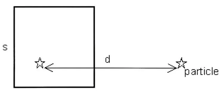
considering its daughternodes.d
j^k
[image:23.549.115.484.362.515.2]particle
Figure 2.1: Barnes-Hut multipole accessibility criterion.
V
denotes the length ofthesideofthecell representingthepseudoparticle. 'd! denotes theeuclideandistancebetween
the particle and the center-of-mass ofthe pseudoparticle. The tree traversal is terminated
The tree hierarchical structure provides the means to distinguish between close parti
cles anddistantparticles without actually computing the distance between every particle.
The force betweenparticles that are close enough are computed
directly,
whereas distantparticles are groupedtogetherand are accounted as one giant node or apseudoparticle. In
order to compute forces from these pseudoparticles, several 'multipole acceptance crite
rion'
(MACs)
are available whichdecideswhetherto accept as itis,
or subdivideit into itsdaughternodes. Thesimplestofthe criterion istheoriginal s/d introduced
by
BarnesandHut Ref.
[5]
and shown in Figure 2.1.Starting
with theroot node, the size ofthe currentnode s (thesidelengthofthe cellcomprisingthepseudoparticle) is compared with its dis
tancefromthe particle,d. Iftheratios/dissmallerthansome predefinedvalue,
9,
then thenodeistaken asisand furthertraversalalongthatnode isterminated.
Otherwise,
the nodeis 'opened'
into its daughter nodes, each of which is recursively examined according to
s/d and, ifnecessary, subdivided. 9 is definedastheMAC parameterand can bevariedto
achieve any desired level of approximation for computing forceson theparticles.
Usually
theMAC provestobeintherange of9= 0.3
1.0,
depending
onthe accuracyneededby
the application. Thesimulation oftheevolution of a system of nbodies overtimeis based
onthe Newtonian equations of motion. The pairwiseinteraction potential
f(i,j)
betweenbody
i andj
canbeexpressed as:G.nii.nii
f(t.3)
= h^(2-1)
where Gis gravitationalforceconstant, m*andrrij representthemassesofthe two
bodies,
and
rfj
representtheeuclideandistance betweenthe twodistinct bodies. Thetotal forceona particleican besummed as:
/()
=/(*,
J)-(2-2)
The Barnes-Hutalgorithm isone ofthe mostwidely implemented astrophysical simu
lationalgorithm. Effortshave been made to parallelizethe algorithmto exploitthe paral
lelismavailableinthe computation partofthealgorithm. Thecore oftheforce calculation
4
itit itit it &
it it it it A s V it
**
\ ***
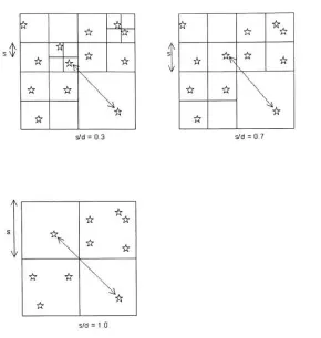
it it it a & * it its/d=0.3 s/d=0.7
A V ft it # it it * & ft
[image:25.549.131.421.86.392.2]s/d=1.0
Figure 2.2: Therelation s/dfor different levelsofthe tree. The figure illustratesthe tree
traversalfor differentvalues of9. When 9 =
1.0,
theforceexerted on theremoteparticleis due to the influence of the entire cell with the side length given
by
s, and computingbody-cell force interaction. If 9 =
0.7,
isassumed, we traversefurther deeper within that
cell and dividethe space into equal spaces, with s again representing the cell side
length,
and againcomputingbody-cell force interaction. If9 = 0.3 is
assumed,wefurther divide
the space evenly and eventually we reach the leafofthe tree, thus computing
body-body
force interaction.
Algorithm 1 StepSystem
MakeTree()
while
loop
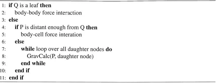
overallbodies doAlgorithm 2GravCalc l 2 3 4 5 6 7 8 9 10 11
if
Q
is aleafthenbody-body
force interaction elseif P is distantenoughfrom
Q
thenbody-cellforce interation
else
while
loop
over alldaughternodes doGravCalc(P,
daughternode)end while
endif
endif
StepSystem( ), as in Algorithm 1 is the routine used for stepping through the
simulation. The routine StepSystem ( ) calls MakeTreeO which constucts a new
octree based on the current particle positions, and then we compute force on each par
ticle/body
using the routine GravCalc () , as shown in Algorithm 2. The routineGravCalc ( ) computestheforceexertedontheparticleP
by
all othernodes,Q. Depending
whetherthenodeQ
is a particle orapseudo-particle,wecomputetheforce exertedby
thatnodeontheparticle P.
In our
implementation,
we used3 different MACs.First,
aminimalcriterion isused wherenocelltouching
theparticle underconsiderationis accepted.
Second,
theoriginal MAC introducedby
BarnesandHutas mentioned above.Third,
theMAC introducedby
Salmon andWarren to eliminate pathological errors [image:26.549.63.494.60.228.2]thatmayoccur whenusing Barnes-Hut MAC [44].
Figure 2.2 shows the effect of9 on the opening angle criterion. As 9 is taken closerto
0,
wetraverse deeper down thetreefor every node withtheforcecomputation more exact as
comparedwiththe forcecomputation when9 istakencloserto 1.
We also eliminated computing quadrupole momemts associated with each cell node.
mapping oftheoctree on the GPU in amemory efficientway. Also it has been observed
thatusingquadrupole orhighercell moments may increasetheaccuracy ofthe forcecom
putations, but this advantage is compensated
by
the increased complexity per evaluation and the highertree construction and the tree storage overhead [48]. Another advantage ofusing monopole moments arisefrom thefact that thedynamical treeupdatesduring
thesimulation canbeperformed inaveryefficient manner.
Barnes-Hutalgorithm has been successfullyparallelized toexploitdataparallelismin
volvedintheforcecomputation,thusmakingthemidealfor high-performancemultiproces sors or vectorprocessors.
However,
suchapplicationtypically
hascharacteristicsthatmake it challengingtopartition and scheduleit foreffective parallel performance. As clearfromthealgorithm GravCalc,theforcecomputations on each particle are
totally
independent ofprevious simulation steps.Also,
we can computeforce interactionsondifferentparticlessimultaneously because the particle positions are only updated at the end of the current simulation step.
Thus,
the force computations are SIMD andthey
can be parallelize to achieve faster computation which results in the reduction ofthe overall simulation time.Recently,
stream processors have been proposedthat may eventually takeplace of vectorChapter 3
Stream
Architecture
and
Programming
Model
Inthischapter wedelve intothedetailsofthestreamarchitecture andits programingmodel.
We study two ofthe ground-breaking stream architectures and their applications to wide
rangingareas.
Modern semiconductor
technology
makes arithmetic inexpensive and memory bandwidth expensive. Both global on-chip andoff-chip communicationthus becomes the per
formance
limiting
factor.Increasing
ratio of arithmeticto memory bandwidthcalled arithmetic
intensity
and parallelismtouse largenumber ofavailable arithmetic unitscan offsetthis shift in cost. Modern multimedia applications emphasize on stream processing pro
grammingmodel.
Stream architecture still in its
infancy
converges these underpinning issueseffectively.Stream architecture dividesthe application to exposethe inherent
locality
and concurrenciesinapplications
by
partitioningthecommunication and storage structures andprovidesexplicit interconnect
(communication)
between functional units and registerfiles. Streamprocessing architecture achieves support for multi-level parallelism also known as con
currency
by
exposing instruction-level parallelism(instructionoverlap inexecution acrossmultiple functional units), dataparallelism
(exposing
SIMD within samekernel)
and taskdifferent
(explicit)
levels of storageforming
adata-bandwidthhierarchy
(register hierarchy), thus reducing the distancetraveled
by
the operands andlimiting
thecommunicationcost. The higher the arithmetic
intensity,
the better the application is suited to streamprocessing architecture. Mediaapplications
including
3Dcomputer graphics, image compression and signal processing have abundant parallelism to take advantage of stream ar
chitecture. Follows below are some of the representative architectures based on stream
processing.
3.1
RAW Machines
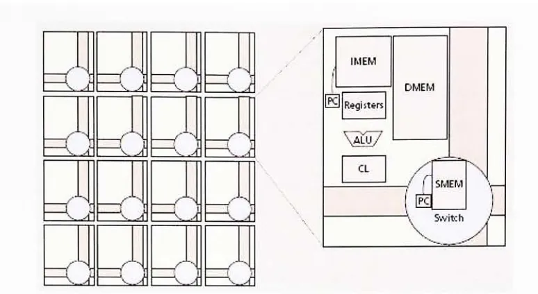
The MIT RAWmachines(Figure
3.1)
provided efficientparallel,pipelined supportformultimedia applications. The RAW microprocessor executes 16 different
load,
store,integer,
orfloating-point instructions every clockcycle,controls 25 Gbytes/sofI/O bandwidth and
has 2 Mbytes of on-chip LI SRAM providing 57 Gbytes/s of memory bandwidth [50].
The RAW microprocessor addresses the issue of wire delays and stream-based multime
diacomputations
by
exposingthehardwarearchitecture'slow-level details to thecompiler.The RAWmicroprocessorrenderssupportinits software
(ISA)
forexplicit communicationto transferdatavalues betweenthe computational portions ofthe tileson aswitched, point
topoint
interconnect,
andthushelps modelingwiredelays. The RAWmicroprocessors alsodiffer fromcurrent superscalar architectures
by distributing
theregisterfiles,
and memoryports, thusrendering support for data locality. Much ofthe hardware support forregister
renaming,instruction scheduling, and
dependency
checking has beenrenderedinsoftware,hence making room formore memory
(distributed)
and computational logic to beplacedon chip. Thisresults in the increase in the arithmetic
intensity
rendering support for dataparallelism, maximizing the number of tiles that can be fit on a chip and
increasing
thechip's achievable clock speed. Multipleprocesses can run simultaneouslywith operations
being
assigned to tiles in a manner that minimizes congestion. The RAW microprocesV /*" >
J
% J f f r A=c
/^ '".3
^ S r .f,A
^
j f [image:30.549.78.465.42.254.2]/"
=<
}
/")
( IMEM DMEM IE Registers\aiu7
CL / r SMEM\
r
|
E3
i SwitchFigure 3.1: RAWprocessor.A RAWprocessorisconstructedusingmultipleidenticaltiles. Each tile contains instruction memory
(IMEM),
data memories(DMEM),
an arithmetic logic unit(ALU),
registers, configurable logic(CL),
and a programmable switch with itsassociatedinstruction memory(SMEM).
low-latency
communicationforefficient execution of scientific compute-intensive andmedia applications. The applications were written in aportable, high-level language called
Streamlt to execute ontheRAWmicroprocessor architecture. Thebasic unit of computa
tionin Streamlt isthe filter. Work formsthecore ofthe filterunit and performs most fine
grained execution step inthe steady state, thus exposing parallelism. In order to support
explicitcommunicationbetween differentcomputationblocksor
filters,
Streamltprovideshigh-bandwidth I/O channels (FIFO queues), which can operate in pop, peek and push
modes.
RAWprocessorsnot onlyrunconventional scalar codes,butalsoword-levelcomputa
tions thatrequireso muchperformace that
they
have been assignedtocustomASIC solutions. RAWprocessorshave beenusedtoimplement Gigabit Internetprotocols, video and
audioprocessing,filtersandmodems,I/Oprotocols
(RAID,
SCSI,
FireWire)
and communication protocolsforcellularphones,multiple channel cellularbasestations,high-definition
3.2
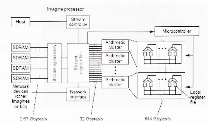
Imagine Stream Processor
The Imagine processor (Figure
3.2) [24]
represents a programmable processor designedto operate
directly
onstreams. The Imaginestream-programming modelmakes communication explicit, and exposesinherent dataparallelism availableinmultimedia applications.
The Imaginearchitecture proposes novel register-filearchitecture andsupports48
floating
point arithmetic unitsineight arithmetic clusters. Eachcluster canbemappedtooperate on
adifferentprocess
by
thestream-programmingmodelusing VLIWinstruction(SIMDfashion). Thestream program organizesdataas streamsand expresses computations askernels
(inmediaapplicationseachkernel iscomposedofhundredsofcomputations), thusexploits
dataparallelism through streams and explicit communication (between streams) between
kernels. A kernel consumes a set ofinput streams of data and generates a set of output
streams ofdata. In order to capturedata
locality,
Imagine(architecture)
divides the register
hierarchy
into local-register files(LRFs),
andstream-registerfiles (SRFs). Datastreamsflow between differentcomputationkernelsisachievedthroughSRFsandintra-kernelstor
age/retrieval ofresults is done throughLRFs
(allowing
explicit communication). As each kernelperformsmany computations(hundredsofcomputations),LRFshelp
maintainhighdata bandwidth needed for reading/writing data
by
different ALUs and handles the bulkofthe data
during
kernel execution. StreamC and KernelC (both uses C-like syntax) areused for writing kernels and applications for Imagineprocessor. StreamC code compiled
by
stream scheduler on the host-CPU sends stream instructions to Imagine's(processor)
stream controllerusing static anddynamicruntime mechanism. KernelC code running on
Imagineprocessoriscompiledstatically using VLIW kerneland sperformskermelcompu
tationsonthesetofinputstreamsandusescommunicationscheduling forexplicit commu
nicationbetweenoperands [35].
Imagine is an on-going researchproject at Stanford
University
andthey
havesuccessfully
used it for varied range of applications.They
have used it for audio and imagecompression and decompression. More recently, Imagine processors have been utilized
advanced communication interconnection networks to give an order of magnitude more
performance per unit costthancluster-based scientificcomputers [13].
Imagineprocessor
Hcsl J Stream
j
conkolter SDRAM c 5 E r|
i
SDRAM SDRAM 25 Netarorkj
devices t (oSier J MiorocDrrtrc ar 81
A'Ihmetic duster Arthrriticduster
\
831
A':hrrr.ic
:!us:er
Imagines I
h Neararfc Interface
JET]
***orI/O) | i
2.67 Sbytes/:
Lom
register He
[image:32.549.99.460.99.310.2]32Gbytes/s 544Sbytesfe
Figure 3.2: Imagine processor. An Imagine stream processor consists of a 128-Kbyte
stream register file
(SRF),
48 floating-point arithmetic units in 8 arithmetic clusters controlled
by
a microcontroller, a networkinterface,
a streaming memory system with 4SDRAMchannels, and a stream controller.
However,
the Imagineprocessor is controlledby
ahostprocessor which sendsinstructionstoit.Wehaveseen above theneedsfor
designing
new architectures andprogrammingmodels to meet the performance and
flexibility
requirements ofmedia applications. We alsosaw thatstreams provide a powerful programming abstractionthathave been suitable for
efficiently
implementing
complex andhigh-performancemediaapplications. Inthelast fewyears, someimportantworkhas been donetoemploystream architectureandprogramming
modelforcomputergraphics application
[40];
[23].[40]
focusedonthedesignandimplementation, and analysis of a computer graphicspipeline on a stream architectureusingthe
streamprogrammingmodel. Imaginewas used asthestreamarchitecture,andan
OpenGL-like pipeline wascompletely implemented on itto illustratethat the streamprocessing ar
chitectures are well suited for graphics applications.
[23]
constructed scalable graphicsof a clusterofoff-the-shelfworkstations. Chromium usesthe notion ofstream processing
to achieve scalability while retainingmaximum flexibility. Bothworks arguedthatstream
architecturescan providethenecessary scalabilityand
flexibilty
neededby
futuregraphicsand multimedia applicationsto achievehigherperformance rate.
Today'sgraphics processor unit orGPU
(VPU)
can process overtens ofmilliontriangles and over a billion of pixels per second, owing primarily to their stream architecture
which enables all additional transistors to bedevoted to
increasing
computational power.On a positive side note, this also has led to the growing use of graphics processor as a
general-purpose stream processing engine. Researchers are exploring the idea and port
ing
more and more applications to use GPUas a general-purpose co-processorto achievehigher performance than on a CPU. In the next chapter we study some of the landmark
graphics architecturesfrom differentgenerations, and alsodetailtheirrecent evolution as a
Chapter
4
Graphics
Processor Architecture
Inthe last chapterwe studied aboutthe stream architecture andprogramming model, and
presentedthat the current generation ofgraphics processor are modelled after stream
ar-chitectture. In this chapter, we study some ofthe important graphics architectures from
different generations, and also introducethe latest generation of graphics processor, more
commonly referred asGPU orVPU. We begin with an overview ontheclassical graphics
renderingpipeline.
4.1
Graphics
Rendering
Pipeline
Theclassic computergraphics-renderingpipeline enumerates aprocessthatgeometricob
jects must experience on their way to
becoming
pixels on the screen. These objects canbe in the form of points, lines or primitives in the shape of polygons and expressed in
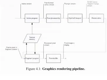
homogeneous coordinate system. The operations performed on the primitives consist of
transformations, divisions
(w-division),
andclippingasin Figure 4.1. An object processedthrough thepipeline seesthecoordinate spacesinthe
following
order:Object Space
Universe Space orWorld Space
Venexstream
Vertexprogram
Transformed vertexstream
Triangleasse-moty
Trianglestream
Screen-space
mappectiange stream
ClipVCuHrViewport
Texture
Coarsepi*e^or
fragmentstream
'
Fragmertprogram
Processedpixel FinalImageto
[image:35.549.89.454.55.328.2]stream display
Figure 4. 1: Graphicsrenderingpipeline.
Perspective Space
Clip
SpaceNormalized Device Coordinates Space
PixelSpace
The transformations form the object space to the universe space is a combination of
translation,rotation,andscalingoperations. This is donetofittheprimitivesintheuniverse
space. Universetoeyespaceconversionconsistsof puretranslationandrotation sothat the
viewing camera or user is placed at the origin and the direction of viewing
being
set to+z axis. Then eye to perspective space conversion is done in order to provide mapping
from 3-D space to 2-D space.
However,
the conversion results intechnically
3-D spacerepresentation with z-axis values stored in the Z-buffer and used later in the pipeline to
enable visible and non-visible effects to the object
being
rendered on the screen. Theoutside the
boundary
coordinates of this volume are rendered invisible whereas objects seen to lie within theboundary
coordinates are made visible on the screen. This spaceis chosen to make the clipping arithmetic simpler. It maps the desired visible chunk of
perspective spaceto afixedregion.
Later,
we performcliptonormalizeddevicecoordinate space transformation in order to represent the objects on an internal pixel independent dimensions. Fromthis internalpixelindependentrepresentation, wetransform theobjects in the hardware pixel space from wherethey
are rendered onto the screen. This spacerepresents the screen real state. The whole rendering process can be performed through
fourmajor steps:
Transformto clippingspace
Clip
Divide
by
w (realclipping spaceas dictatedby
the screen)Transformto pixel space
4.2
Graphics Hardware
According
to one classification of computer graphics architectures[2],
various genera tionscanbeclassifiedby
thecapabilitiesforwhichthearchitecturewasprimarily designed(target capabilities with maximized performance) and not
by
the scope of the capabilities. Anotherclassification categorizesthemonthebasis of
technology (ASIC, DSP,
RISCCPU,
and CPU extensions), arrangement (SIMD orMIMD),
and programmability(end-userprogrammablity and the relative ease with which
they
were programmed) [32]. Weusethelatterclassification methodtodiscussthemotivationbehindvarious
(representative)
graphics architectures.
down on system costs. We describe some of the landmark graphics architectures, and
presentthelatest generation ofGPU.
Geometry
Engine,
1982Channel Processoror
CHAP,
1984Polygon-Rendering Chip
orPRC,
1986High Performance Polygon
Rendering
Architecture,
1988PixelFlow,
1992Indigo
Extreme,
1993RealityEngine,
1993InfiniteReality,
1997Programmable Graphics
Architecture,
20014.2.1
Geometry
Engine
One of the earlist design effort was the development of the
Geometry
Engine[10]
forGeometry
Graphics System (IRIS Graphics System). TheGeometry
Enginewas aspecial-purpose, four component vector, floating-point processor for accomplishing three basic
floating-point operations; matrix transformations, clipping and viewport transformations
in computergraphics applications. The
Geometry
Engine provided limitedflexibility
andcouldbeconfiguredtoact as a partofthematrixsubsystem,clippingsubsystem andscaling
subsystem inthegraphicsrenderingpipeline. The
Geometry
Systemwas a slave processorand could only accept or yield one format of data and instructions. The graphical primi
tives were stripped into individual coordinates or vertices and each component processed
in a pipeline orderto achieve performance ofthe order of 5 million floating-point opera
tions per second. The programmingmodel ofthegraphicssystem wasused asahardware
subroutineto theIRIS processor/memory system andthus wasspecificto theplatformand architecture ofthe
host/controlling
processor.4.2.2
Channel Processor
The system called Lucasfilm Compositor used the channel processor or CHAP
[30],
aspecial-purpose, fourcomponent vector, programmable pixel processorto provide digital
processing capabilities for special-effects filmproduction. The CHAP performed all the
computations and controlledtheflow ofpixels(madeoffourcomponents; red, green,blue and alpha) in the Compositor. Scratchpad memories provided for program data storage
couldbereferencedfor fouror one operand
by
any arithmetic operation. Vectorarithmeticunits connectedto thescratchpadmemoriesthrougha crossbar networkthus allowediden
tical or different operations to be performed on all the fourpixel components in parallel.
TheCHAP's datapath wasoptimized for 16-bit integeroperations. Inorder to render rich
images for film applications, for the first time framebuffer memory banks were config
ured with 12-bits per channel. The CHAP performed single
instruction,
fourcomponentprocessing (SIMD). One of the unique features of CHAP was the support for
disabling
some subset of processors over a rangeof operations likeclamping. Applicationsrequired skilledprogrammingefforts and couldbecomplicated
by
thepipelinedelays built into thehardware modules. Pixar's CHAP could provide interactive usage on limited resolution
images while acceptable performance for high resolution, movie quality images required
offline rendering.
4.2.3
Polygon-Rendering
Chip
Image rendering becauseofitscompute-intensive nature representsthemajorperformance
necessary components needed forreal-time image rendering were put onone-chip VLSI
implementation. The chip knownaspolygon-rendering chiporPRCwasdesignedprimar
ily
formechanicalengineering CAD applications [49]. CAD applications requireinteractive manipulation of solids (shaded polygons). In order to render real-time performance,
PRC facilitated pipelining and internal bandwidth for computation and communication.
The performance was maximized
by
pipelining differentparts ofthe fill and shading algorithms and running different functional blocks in parallel. This made the architecture
unique in the sense thatdatacouldbemovedfromone functional blockto another in one
clock cyclevia register-registertransfers. The architecture also used pixel cache so
frame-bufferwrites andZ-bufferaccesses couldbe done inparallel.
4.2.4
High
Performance
Polygon
Rendering
A novel graphics subsystem was developed to meet the demands for
displaying
realistic solid objects and support for real-time image rendering and independent windows.
The graphics subsystem was partitioned into four special-purpose pipelined subsystems;
geometry, scan-conversion,raster and
display
subsystem with eachperformingadedicatedtask [3]. Each ofthese subsystems were pipelined into various functional blocks. The
Geometry
subsystem comprising ofGeometry
Engines was organized as asinglepipelineof floating-point processors with each executing a specific subset of geometric transfor
mations.
Geometry
Engines operatedindependently,
thus rendering support for SIMD.When takentogether, goemetrysubsystem achieves an efficiency of50% notseen
by
vectorprocessors used in other graphics systems present at the same time. Scan-conversion
subsystem responsibleforconvertingvertexdata (from geometry subsystem)to individual
pixels comprised ofPolygon processor, Edge processorand five Span processors (operat
ing
parallel) arranged in pipeline with each composed offixed-point engines. Five Spanprocessors againoperating in SIMDacheived anaggregatefillrateof40million pixels per
second. Rastersubsytemwaspipelinedinto
twenty
ImageEngines,
each of which operatedoperation).
They
resultedin extremely powerful andflexible pixelfill operations not seenby
other graphics systems atthe same time. Andfinally
theDisplay
subsytem interpretedpixels from the frame-buffer memory and routed it to the DAC for display. The graphics
subsystem produced somebrilliant operatingnumbers
(rendering
100,000Gouraudshadedand Z-bufferedpolygons per second) and represented a unique graphics system skeleton
thatwasfollowed
by
subsequent graphics architectures. Someofthespecial featuressupp-portedwere pan and zoom, window ID masking, real-time video, alpha
blending
andan-tialiasedlines.
4.2.5
Indigo Extreme
One of the
limiting
factor of the High Performance PolygonRendering
design was itschoice forthehostprocessor. This choice made the design only suitedforone particular
kindof platformand thusrenderedlimited programmability and portabilityto otherhard
wares. Other disadvantages include the throughputof various subsystems
being
dictatedby
the speed ofthe slowestprocessing step. This results ina non-linear performance gain.Considerableoverheadisadded witheach processorinsubsystem stagesintheformofse
quencer, microcodestore, globals data storeandinterface logic between differentpipeline
stagesresulting in thelossof performance.
In order to eliminate the above mentioned design limitations and disadvantages and
to circumvent the bottlenecks seen in the floating-point compute-intensive units used in
the geometry subsystem, compute-intensive arithmetic units used in the scan-conversion
subsytem, the limited fill rate andthe pixel bandwidth as seen into the
frame-buffer,
SGIintroducedaunique computer graphicsarchitecture oftheIndigo Extreme aimed at maxi
mizing performance while minimizing size [20]. The decision was made to combine the
per-vertexand slope calculations into one unit. The slope calculations were implemented
in amicrocoded processorbecauseofrelativelycomplex algorithms involved. The advan
tagesachievedthroughthisapproachresultedintheincreaseinvertex and slopeprocessing
floating-pointfunctional units were implemented.
Geometry
Engine design approachfollowed the fundamental design principle of maximizing the performance of most expen
sive functional units. This was achieved
by
providing custom design data paths to theoperands and support for multiple threads of the same algorithm active simultaneously.
Multi-portregisters were used to render support formultiple simultaneous threads ofcal
culation. More than one
Geometry
Engines were usedin SEMD parallel approach insteadofsingle pipeline ordertoattainalinearperformnace gain with minimal overhead required
to implement it. This resulted in the processing of eight polygons
(primitives)
in parallel.
Hyper-pipelining
was used fordesigning
Raster Engines instead of using multiplecopies in an SIMD parallel approach. This was done to minimize the area requirements
while achieving the desired performance.
Memory
bandwidth was increasedby
using aninterleaved frame-buffer across multiple memory banks. The resulting architecture was
capable of over 500,000 Gouraud shaded Z-buffered polygons per second and a fill rate
of 80 million pixels per second.
However,
the design was particularly suited to one kindof application (CAD programs).
Any
deviation from this fixed-function implementationresultedin significant performanceloss.
So farwehave mentioned architecturesthatusedspecial-purpose, fixed-functionchips
(ASICs)
forgeometrictransformationsandimage renderingarrangedineitherfine-grainedor course-grained SIMD arrangement. These graphics architectures processed graphical
primitives as independent vertices or coordinates. Some ofthe disadvantages have been
outlined withthedescriptionofeach architecture. SIMDarchitecturesdonot scale
linearly
with the number of geometric engines or image Tenderers. Several important architec
tures basedon MIMD (multiple instructionmultiple
data)
arrangementwere introducedtoresolve these issues. MIMD arrangements processed the vertex stream as a part of a geo
metric primitivethusenablingoperationslike cullingandreducingtheprocessingtimeand
increasing
parallelism. Here we discusssome ofthese importantarchitectures and outline4.2.6
PixelFlow
PixelFlowarchitecture
[38]
overcamethescalinglimitationaswellasthegeometrictransformations and frame-buffer bottlenecks
by
using the technique of image composition.Imagecompositiondesigned forreal-time
(30Hz)
3Dgraphics algorithmsand applicationsachievedhigh renderingperformance
by
applyingobject parallelismthroughoutthegraphics renderingpipeline. The rasterization processors
(renderers,
shaders andframe-buffers)
were associated with aportion ofthe primitives
(occupying
128x128 pixel regions ofthescreen), rather than a portion of the screen which is termed as image parallelism. Each
Tenderercomputes pixel values for its primitives regardless oftheir viewport association.
Thecomputedpixelvalues arethen transmittedover a networktocompositingprocessors,
whichresolvethe visibilityofpixelsfromeach Tenderer. Someoftheunique architectural
featuresoffered
by
PixelFlow were intheformofsupersampling antialiasingand deferredshading mechanism. This distribution mechanism of primitives is alsoclassified as
sort-last mechanism [37]. Sort-last mechanism issues someoutstanding features in the form
of linear scalability and
being
less prone to load imbalances. PixelFlow can be scaledlinearly
to achieve tens of millions of polygons per second. PixelFlow could be configured to operate as a part ofworkstation or parallel computer. One distinct feature was
that all the components of PixelFlow were general-purpose, programmable and offered
a simple programming model. PixelFlow rendered complex primitives such as spheres,
quadrics and supported real-timeillumination models,procedural andimage-basedtextur
ing,
environmentmappingand restrictive antialiasing. Somemajorlimitationswerethat theimage-composition network mustsupportvery high bandwidthcommunicationto transfer
128x128pixel region of pixeldata. PixelFlowsuffered significant performanceloss incase
ofload imbalances. PixelFlow could also render the final image once all the primitives
corresponding to the logical tiles hadbeen transformedand sorted. This limitation could
4.2.7
RealityEngine
RealityEngine is a massively parallel computer graphics architecture developed
by
SGI.SGI classified RealityEngine (Figure
4.2)
as their third-generation design primarily forreal-time(15-30
Hz)
rendering of textured mapped, antialiased traingles. TheGeometry
lV>l'ni dus. Command Process
Engfees
~
Fragment w
dwserators;
ii
ii
ii ii
ii
nil ii n n
frcage_
Engfcnes
tfi frifli-M*+t -[*
riEin i.-J!W3rjr^rd
tlHlltll *-iS--iHrl !
nrfteic^onKvy bj*i
! Gfepljy^GHE r;tbl :-*ii.nJ;
Figure 4.2: RealityEngine block diagram. Board-levelblock diagramof anintermediate
configuration consisting of 8
Geometry
Engines,
2 raster memoryboards,
and adisplay
generatorboard.
Engineperformed multiple
instruction,
multiple componentprocessing andrequiredhand-codedassemblycodetoextractthegreatest performance. Texture mappingrenderesimages
that are
highly
visuallyinteresting
and lookedmore realistic. PixelFlow rendered texturemapped images but RealityEngine provided expansive support in thehardware to gener
ate such detailed images. Fragment Generators incorporatedwere fixed-function pipeline
unit and performed the initial generation of
fragments,
generation ofthe coverage mask,texture addressgeneration, texture
lookup,
texturesamplefiltering,
texture modulation ofthe fragment color and
fog
computation and blending. RealityEngine also supported1-and 3-dimension texture maps and thus could be used torender volumetric images. An
[image:43.549.168.381.170.357.2]beperformedeither
by
single-pass (PixelFlow didnot supportthis menthod)or multi-passantialiasing methods. Unlike
PixelFlow,
RealityEngine separated the transformation andfragmentgenerationrates. Thismade possiblethe fine
tuning
ofthe architectureforunbalancedrendering requirements. Image Engines were assigned a fixed subset ofthe pixels
intheframebuffer. Unlike
PixelFlow,
allthe different functional blocks running inparallelcould complete the final image as soon as the last primitive was rendered
by
the ImageEngine. Thecolorcomponentresolution was increased from 8-bits to 12-bitsto eliminate
visible
banding
and support for substantial framebuffer composition. RealityEngine usedbothobjectparallelismandimageparallelismto achievevery highperformance rates. Ob
ject parallelism implies partitioning either the geometric description of the scene where
vertices of a geometric primitive are processed
independently by
different processors inparallel or theassociated object spacewhere different geometric primitives areprocessed
independently
by
differentprocessors inparallel. Imageparallelismsplitstheimage spaceas fragments where each fragment is processed
independently by
different processor inparallel.
4.2.8
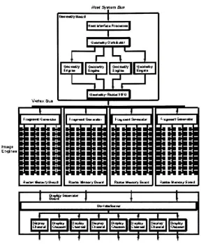
InfiniteReality
The
InfiniteReality [39]
graphics system architecture shown in Figure 4.3 was designedwith the primary goal of real-time application performance. The architecture was devel
oped as a superset ofRealityEngine graphics system. Unlike previous mentioneddesigns
where
display
list processing had been handledby
thehostprocessor,InfiniteReality
introducedlocal
display
listprocessingby
the graphics subsystemto eliminatehostto graphicsI/O bottlenecks. RealityEngine and previous architectures distributed primitives among
different
Geometry
Engines usinground-robinmechanism. As theGeometry
Engines operatedinanMIMDarrangement,
InfiniteReality
extendedthesupportforleast-busy
distribution mechanism which offered performanceadvantage over ubiquitous round-robinmech
nfevffyrtraiSue V-fi**L-i tniaiVUK'
t
#|jkHliOifli***4*ii!i '1
tga 1 1feaJBw 1 1Saga* ||fogfcMii |
5T=*
|giiiHSiwar-fcui-HM]
tn*i
r
r
L
f'
]
11 imp<rr*'..-*Jui 1tiqpmm torn*ma II^lM^M-M^ f"i|p'*liirl"ii>IMTtiri- 1I
4m* III
r
I 1III lllllll ! tjlUi llMMf>dMi.ii
E
|
l^|4a^j
T
t**4MWi'l,
f
1.1
:,
k.
f
i
,jl3
r
\
i
i
i
^
it
Figure4.3:
InfiniteReality
Engine block diagram. Board-level block diagramofInfinite-Reality
Engine withmaximum supportfor4Geometry
Engines,
4 RasterMemory
baords,
and aDisplay
Generator boardwith8outputchannels.with four stage pipelined arithmetic units executing pixel-components in SIMD arrange
ment. The screen-space primitives were then input to the Raster
Memory
board whichcomprised of a Fragment Generatorandeighty Image Engines. Unlike previous architec
tures, theFragmentGenerators in
InfinteReality
assembled screen-space primitives (triangle setup) and computed parameter slopes. The performance of
InfiniteReality
graphicssystem made possible theuse ofvery large texturedatabases
by
introducing
a representation called clip-map, and multipass rendering techniques to implement reflections, shad
[image:45.549.132.420.54.404.2]for very large textures while multipass rendering techniques can enhance visual realism.
The
display
generator board provided support for flexible and software controlled videoarchitecture thatcoulddrive upto eight autonomous
display
output channels. To counteractfill-rate
bottlenecks,
InfiniteReality
graphics systemintroduced dynamicvideoresizingwhere the scene is rendered to the frame-buffer at a potentially reduced resolution such
that primitives are drawn in less than one frame time. Despite the success ofMIMD ar
chitectures, SIMD systems offered a simpler programming model. This is owing to the
fact thatMIMD systems imposes aburden on applications and operating systems, which
must be able to cope with the arrival of data at unpredictable intervals and in arbitrary
order. This often resulted in the design of complex and cumbersome communication and
buffering
protocols rendering software overheads. SIMD systems operating in thelock-step fashion virtually eliminates these overheads.
Also,
it is often possible to structurealgorithms as several distinct functional
blocks,
each of which operates on a uniformdatatype. The rendering pipeline maps naturally onto this structure, and the regularity of the
datastructures within eachphaseleadsto uniformoperations,providingagoodfitwiththe
SIMD programming paradigm.
Finally,
SIMD architectures usually contain thousands ofsimpleprocessing elements. Becauseoftheirsheer numbers, goodperformance can often
beachieved even thoughprocessors may notbe
fully
utilized [12].4.2.9
Graphics Software Libraries
The realm of computer graphics applications was growing but there was no real coordi
nated effortto
develop
hardwareindependentgraphicssoftwarelibrariesthatcouldbeusedto render simple or complex scenes effeciently. All the above mentioned graphics sys
temdesignsweredeveloped
independently
withoutanycoersiontowardsindustry
standardcompliance. These graphics systemscould notbe implemented on avariety of platforms
with a range of graphical capabilities. There existed several independent standards most
(PHIGS extensionto X window system)
[15]
thatcould render 2D or3D objects on limitedgraphics systems withlimitedgraphical capabilitiesmakingprogramportability
prob-lemetic. Also we have mentioned that it required considerable knowledge and expertise
to program graphical applications effeciently and was mostly carried out
by
thesystems'
designers. OpenGL developed
by
SGI is an emerging graphics standard. Itis alow-levelgraphics
library
specification thatprovides advancedrenderingfeatures whilemaintaininga simple andflexible programmingmodel. OpenGL is rendering-only,so it is independent
ofthemethods
by
whichtheuserinputand other window or non-window systemfunctionsare achieved, making the rendering portions of the graphical program thatuses OpenGL
platformandoperatingsystemindependent.
4.2.10
Streaming
CPU Extensions
PixelFlow, RealityEngine, InfiniteReality,
etc represented massively parallel graphics architectures with variedrange of capabilities.
However,
the above mentioned graphics architectures were accessibleatvery highcostforspecial-purposes. Technological advance
mentsintheVLSI
technology
made possible visual realism experiencefordesktop
personalcomputers
by
incorporating
SIMD arrangement inthe general-purpose processor designs.In