Paper No. P08-T14 N Srinil et al Total number of pages = 8
New Model for Vortex-Induced Vibration of Catenary Riser
Narakorn Srinil a, b, Marian Wiercigroch a, Patrick O’Brien b, Michael Lane b
a
Centre for Applied Dynamics Research, School of Engineering, University of Aberdeen, King’s College, Scotland, UK
b
MCS, Aberdeen, Scotland, UK
ABSTRACT
This paper presents a new theoretical model capable of predicting the vortex-induced vibration response of a steel catenary riser subject to a steady uniform current. The equations governing riser in-plane/out-of-plane (cross-flow/in-line) motion are based on a pinned beam-cable model accounting for overall effects of bending, extensibility, sag, inclination and structural nonlinearities. The empirically hydrodynamic model is based on nonlinear wake oscillators describing the fluctuating lift/drag forces. Depending on the potentially vortex-induced modes and system parameters, a reduced-order fluid-structure interaction model is derived which entails a significantly reduced computational time effort. Parametric results reveal maximum response amplitudes of risers, along with the occurrence of uni-modal lock-in phenomenon. KEY WORDS: Catenary riser; vortex-induced vibration; wake oscillator, fluid-structure interaction, reduced-order model; empirical coefficient; uniform current.
INTRODUCTION
Steel catenary riser (SCR) has become a primary candidate for future ultra deepwater oil/gas industry because it offers the most promising technological and commercial solution. One of the key issues in the analysis and design of SCRs is to estimate and control the fatigue damage due to vortex-induced vibration (VIV). Nevertheless, current industrial knowledge of VIV prediction is still based on an empirical science and on a simplified linearized model of straight (e.g., top-tensioned drilling/production) risers and pipelines. Therefore, many uncertainties arise when designing the SCRs which are actually flexible inclined cylinders, having initial sags and varying curvatures. As a matter of fact, SCRs are substantially different from top-tensioned risers (TTRs), in view of the current flow direction relative to the pipe axis, which is arbitrary and different from 90o when the flow aligns with the SCR plane of curvature. Moreover, a slender long beam-cable system has multiple natural frequencies which potentially give rise to different in-plane/out-of-plane multi modes in cross-flow/in-line VIV. Nowadays, numerous frequency and time domain tools for predicting nonlinear dynamic responses of straight vertical risers experiencing
VIV are available in industry. In spite of this, the state-of-the-art comparisons of VIV responses still exhibit remarkable discrepancies (Larsen and Halse, 1997; Chaplin et al, 2005), and not much is really known about the VIV of SCRs. Perhaps, the simplest and cost-effective way to deal with the hydrodynamics and to recreate the associated fluid forces acting on the underwater cylindrical body is to implement a phenomenological wake oscillator model. Essentially, this empirical model contains some parameters deduced from experimental data. In this study, we utilize a new nonlinear wake oscillator model of Skop and Balasubramanian (1997) which has been developed based on some experimental collections of both elastically-mounted rigid and flexible cylinders subject to uniform flow. It has recently been used in predicting the VIV responses of horizontally suspended cables (Kim and Perkins, 2002). To overcome some limitations of a typical vertical riser model, we propose a general and realistic theoretical model valid for SCRs with arbitrary sags and inclinations. By coupling the wake oscillators to the riser nonlinear equations, a reduced-order model governing the hydro/elastic-cylinder interaction is derived and solved in the time domain, based on the potentially vortex-induced modes. In particular, we aim to predict the uni-modal lock-in phenomenon and the attainable maximum amplitudes of SCRs due to both cross-flow and in-line VIV in a sub-critical flow range of the Reynolds number (Re). FLUID-RISER INTERACTION MODEL
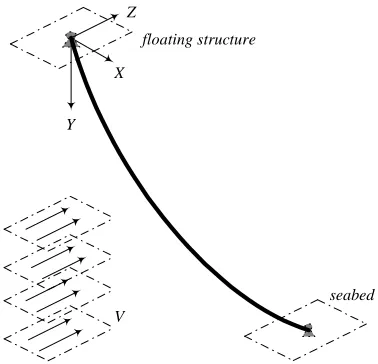
With reference to a fixed Cartesian co-ordinate system, Fig. 1 displays a 3-D continuum model of SCR connected from a stationary floating structure to a seabed with simply pinned-pinned supports. A horizontal offset XH and water depth YH define a chord inclination angle of riser
(i.e. θr = tan-1YH/XH). Riser properties are spatially uniform, with
mass/length (m), viscous damping coefficient (c), hydrodynamic diameter (D), effective bending (EI) and axial (EAr) stiffness. As an
initial consideration, the steady incoming flow, having density (ρ) and normal velocity (V), is considered to be uniform in the Z+-direction
perpendicular to the SCR plane (XY) of initial equilibrium curvature. Following the Strouhal number (St) law, this entails a single natural frequency (rad/s) of vortex shedding or wake (ωs) behind the stationary
Fig. 1 Schematic model of SCR subject to uniform current flow
Nonlinear Equations of Riser 3-D Motion
By considering the riser as a flexural sagged cable-like elastic structure satisfying the Euler-Bernoulli beam hypothesis, the nonlinear partial-differential equations of riser motion about its planar (XY) static equilibrium may be expressed in dimensional form as
(
)
22 02 2 2 2 2
1
2 2
1
, 2
a r
u u u x u y v
m m c T EA
t t s s s s s s
u v w x u x u
EI F
s s s s s s s s
∂ ∂ ∂ ∂ ∂ ∂ ∂ ∂
+ ∂ + ∂ =∂ ∂ + ∂ ∂ +∂ ∂ +
∂ +∂ +∂ ∂ +∂ − ∂ ∂ +∂ +
∂ ∂ ∂ ∂ ∂ ∂ ∂ ∂
(
)
22 02 2 2 2 2
2
2 2
1
, 2
a r
v v v x u y v
m m c T EA
t t s s s s s s
u v w y v y v
EI F
s s s s s s s s
∂ ∂ ∂ ∂ ∂ ∂ ∂ ∂
+ + = + + +
∂ ∂ ∂ ∂ ∂ ∂ ∂ ∂
∂ ∂ ∂ ∂ ∂ ∂ ∂ ∂
+ + + − + +
∂ ∂ ∂ ∂ ∂ ∂ ∂ ∂
(
)
22 02 2 2 2
3 2 1
(1a-c) 2
a r
w w w x u y v
m m c T EA
t t s s s s s s
u v w w w
EI F
s s s s s s
∂ ∂ ∂ ∂ ∂ ∂ ∂ ∂
+ ∂ + ∂ =∂ ∂ + ∂ ∂ +∂ ∂ +
∂ +∂ +∂ ∂ − ∂ ∂ +
∂ ∂ ∂ ∂ ∂ ∂
in which s (t) denotes Lagrangian or arc-length coordinate (time). u (x) v (y) and w represent global dynamic (static) displacement in the horizontal (X), vertical (Y) and transversal or out-of-plane (Z) direction, respectively. T0 denotes axial static tension of riser due to effective
weight, ma denotes potential added mass (CAρAr, where Ar is circular
cross-sectional area, CA=1), and Fi denotes external hydrodynamic
(lift/drag) forces leading to VIV. By accounting for both bending (e.g., Ricciardi and Saitta, 2008) and axial (e.g., Srinil et al, 2007) rigidities, Eq. 1 is also valid for a top-tensioned riser (TTR) or horizontal pipeline with zero sag, and accounts for overall inertia effects (Srinil and Rega, 2007b) and structural nonlinearities which are meaningful in the case of large displacement or deformation of SCR. It is worth noting that the effects of shear, torsion, seabed and internal-flow-induced friction forces, which are quite important for SCRs, are not herein accounted for. In the following, all the space-related variables and associated equations are non-dimensionalized with respect to D.
Submerged Configuration of SCR
For simplicity in an analytical study, it is herein assumed that a 2-D submerged static configuration of SCR is solely due to its effective self weight, whereas the bending restraint and the uniform current flow play a role after the performance of static equilibrium. The neglected static bending is plausible because the end boundaries are pinned-pinned and the SCR curvatures are relatively small. Accordingly, the higher-order spatial derivative of x and y in Eq. 1 is disregarded, and the catenary static profile is simply governed by
2 1
H
E
T
y W y
D ′′= − + ′ (2)
in which a dash denotes differentiation with respect to x, WE is the
effective weight accounting for buoyancy effect, and TH is a horizontal
component of riser tension which is spatially constant. By directly integrating Eq. 2 twice, the exact hyperbolic function-based formula describing the catenary configuration reads
1 2
( ) H cosh E
E H
T W D
y x x C C
W D T
− −
= + +
(3)
where C1 are C2 are determined based on boundary conditions. Thus,
for a given D, WE, θr, XH and TH, the SCR equilibrium can be explicitly
determined and then substituted into Eq. 1 as an embedded function. Nonlinear Wake Oscillators
As the considered current flow is normal to the SCR plane, the cross-flow (in-line) VIV due to lift FL (drag, FD) force corresponds to
in-plane (out-of-in-plane) motion of SCR. Thus, by neglecting the tangential hydrodynamics, the excitation forces per unit length in Eq. 1 read
2 1
1
sin sin
2
L L
F = −F θ= − ρC DV θ (4)
2 2
1
cos cos
2
L L
F =F θ= ρC DV θ (5)
2 3
1 2
D D
F =F = ρC DV (6)
where θ is a local angle of inclination (measured clockwise from the X-axis in Fig. 1) based on Eq. 3, in which θ≈ tan-1(y′). CL (s,t) and CD (s,t)
are unsteady lift and drag coefficients per unit length, respectively. It is worth noting that the mean drag, and possibly also the mean lift (Miliou et al, 2007), component, which potentially gives rise to a new SCR equilibrium, is here omitted as we focus on the fluctuating component.
Lift Coefficient for Cross-Flow VIV
The wake oscillator Q(s,t) of Skop and Balasubramanian (1997) has been developed by particularly focusing on the cross-flow VIV. It copes well with damped and lightly-damped systems. Based on the van der Pol oscillator, CL(s,t) and Q(s,t) are originally represented by
( )
( )
2( )
, , ,
L N
s
C s t Q s t γY s t
ω
= − ɺ (7)
( )
(
2 2( )
)
( )
2( )
( )
0
, s L 4 , , s , s N ,
Q s tɺɺ −ωG C − Q s t Q s tɺ +ωQ s t =ωFYɺ s t (8)
where γ is a so-called stall parameter (Triantafyllou et al, 1994), YN is a
Y X
Z
V
local displacement normal to the riser, CL0 is the lift coefficient for a
stationary cylinder, and a dot denotes differentiation with respect to time. To describe the two displacement components of SCR in-plane motion, we let QX = -Qsinθ and QY = Qcosθ, thereby giving rise to
2 2 2
0
3 4
sin sin sin sin sin
X s L X s X X s X s
Q ωGC Q ωGQ Q ωQ ωFu
θ− θ + θ + θ = θ
ɺɺ ɺ ɺ ɺ
(9)
2 2 2
0
3 4
cos cos cos cos cos
Y s L Y s Y Y s Y s
Q ωGC Q ωGQ Q ωQ ωFv
θ− θ + θ + θ = θ
ɺɺ ɺ ɺ ɺ
(10)
Clearly, Eqs. 4 and 9 (5 and 10) are dependent on both QX and uɺ(QY
and vɺ), exhibiting the two-way feedback coupled system of the wake-riser interaction. Note that, in place of Eqs. 9 and 10, Eq. 8 is considered for a straight vertical riser or horizontal pipe. Overall, the empirical wake coefficients are obtained by matching and interpolating a series of experimental data from many research groups (Skop and Balasubramanian, 1997), and they are dependent on the mass-damping (so-called Skop-Griffin) parameter SG = ξ/µ, in which ξis the modal
damping in water and µ is the mass ratio given by
(
)
2
2 2
8 St a
D
m m
ρ µ
π =
+ (11)
Drag Coefficient for In-Line VIV
Very few theoretical studies have proposed a wake oscillator governing the drag coefficient, and a practical tool for predicting the in-line VIV is still unavailable in industry. It is well known from many experiments (e.g., Okajima et al, 2004) that the in-line VIV may take place in a reduced velocity range lower than that of cross-flow VIV with symmetric/alternate vortices. In addition, it may take place in the same reduced velocity range as cross-flow VIV with alternate vortices. Typically, the in-line VIV has a frequency twice that of cross-flow VIV during a 2-D lock-in. This entails that both out-of-plane and in-plane modes, whose natural frequencies are in nearly-tuned 2:1 ratio, are simultaneously excited. Based on this evidence and considering the practical case of alternate vortices, we here utilize, by following Currie and Turnbull (1987), Kim and Perkins (2002),
( )
( )
1( )
2( )
, , , ,
2
D
s s
C s t P s t P s t γw s t
ω ω
= + ɺ − ɺ (12)
( )
(
2 2( )
)
( )
2( )
( )
0
, 2 s D 4 , , 4 s , 2 s ,
P s tɺɺ − ωH C − P s t P s tɺ + ω P s t = ωJw s tɺ (13)
where P is the in-line wake component, H and J are empirical coefficients, and CD0 is the drag coefficient of the stationary cylinder.
Natural Frequencies/Modes with Bending-Tension Effect
Natural frequencies and mode shapes of pinned-pinned SCRs (as well as TTRs) are determined by a hybrid analytical-numerical solution. By considering x as an independent variable, from Eq. (1), the linear equations of undamped free in-plane (u, v) and out-of-plane (w) motion are expressed, in dimensionless form, as
2 2
3 3 3
1
1 y 0
u b u c α u α v
κ
κ κ κ
′
′ ′
′′′ ′ ′
+ − + + =
ɺɺ (14)
2
2 2
3 3 3
1
1 0
y y
v b v c α u α v
κ
κ κ κ
′ ′ ′ ′
′′′ ′ ′
+ − + + =
ɺɺ (15)
2 2
3 1
0
w b w c w
κ κ
′
′′′ ′′
+ − =
ɺɺ (16)
where κ = (1+y′2)1/2, α = EAr/TH, b2 = EI/(m+ma)D4, c2 = TH/(m+ma)D2.
In-plane and out-of-plane modes are postulated, based on a Fourier sine series satisfying the boundary conditions, in the form
( )
( )
1
, sin
N
J J
n
n H
n xD
U x t t
X
π
=
= ϒ
∑
(17)where, for J = 1-3, U1 = u, U2 = v, U3 = w, ϒJn are generalized time
coordinates, N is number of convergent sine functions. By substituting Eq. 17 into Eqs. 14-16 and applying the Galerkin method, the eigen-problem is solved in the same manner as in Srinil et al (2007). Note that, for a pinned-pinned TTR with uniform tension and bending, both frequencies and modal shapes can be alternatively obtained via closed-form closed-formulae, and both kth in-plane/out-of-plane modes are similar to taut-string (sine-based) modes. However, this is not the case for SCRs whose in-plane modes are significantly dependent on initial sagged configurations, and indeed they are neither purely symmetric nor anti-symmetric modes due to the effect of catenary inclination.
Natural Frequency Spectrum for Riser
It is worth constructing a spectrum of natural frequencies (in still water) to understand the global picture of in-plane/out-of-plane frequency relationships when varying some key parameters of the riser system. This is useful in view of detecting the potential VIV modes. Due to the combined effect of bending, extensibility (tension) and geometry (sag/ inclination), two meaningful non-dimesional parameters are introduced,
(
)
22 3
cos /
E r r a
W L EA T
λ = θ (18)
a
L T EI
∆ = (19)
where L is riser equilibrium length and Ta is the tension at maximum
sag. The parameter λ2is a so-called cable parameter (Srinil and Rega, 2007a) describing the elasto-geometry effect, whereas ∆ is a so-called tensioned-beam parameter describing how the flexural (small ∆) or axial (large ∆) rigidity plays a dominant role. By normalizing the SCR frequencies (ω) by the lowest frequency of the corresponding TTR (ωT), the frequency spectrum with ω/ωT vs. ∆ is illustrated in Fig. 2,
[image:3.595.324.536.537.705.2]where solid (dotted) lines denote in-plane (out-of-plane) modes.
Fig. 2 Natural frequency spectrum for risers with varying ∆
∆
160 200 240 280 320 360 400 440 480 520 560
ω/
ωT
0 1 2 3 4 5 6 7 8 9 10 11 12 13 14 15
Top-tensioned riser Catenary riser
In-line VIV mode (dotted line)
In Fig. 2, where Ta (L) is varied, ∆ > 560 represents the case of TTRs
(λ 0, as WE effect becomes negligible with respect to Ta) whose kth
in-plane/out-of-plane frequencies are equal. However, a decrement in ∆ reflects the case of SCRs whose kth in-plane/out-of-plane frequency
ratio is changeable. In some cases, the computed vortex frequency ωs
(for a given V) entails the potentially in-line/cross-flow VIV modes having a 2:1 frequency ratio, as exemplified by the circles corresponding to the 6th out-of-plane/2nd in-plane modes for ∆≈ 272 (vertical dashed line). When further increasing V (thus ωs) for such ∆, it
is also possible that two higher-order (5th and 6th) in-plane modes – whose frequencies are nearly equal at a so-called avoidance region (Srinil and Rega, 2007a) – may be simultaneously excited. This may result in a multi-mode lock-in of cross-flow VIV (Hover et al, 1997). Yet, our attention is placed on the uni-modal lock-in behavior observed through a reduced-order model derived in the following.
REDUCED-ORDER MODEL FOR UNI-MODAL VIV
To the aim of minimizing the computational time effort, a reduced-order model describing the hydrodynamic-elastic cylinder interaction is now developed, by assuming that both the fluid (i.e. wake) and the riser dynamically displace in a similar fashion having a certain spatial shape profile corresponding to a potentially vortex-induced mode. This is plausible (see, e.g., Skop and Griffin, 1975; Kim and Perkins, 2002) because the flow is uniform and its direction is perpendicular to the SCR in-plane curvature, giving rise to a single vortex shedding frequency. Moreover, based on the fact that the VIV amplitude is relatively small (Sarpkaya 2004), the contributions from higher-order modes through structural nonlinearities may be negligible (Srinil and Rega, 2007b). The first-order (state-space) differential forms of Eqs. 1, 9, 10 and 13 are considered, and the expansion of displacement and velocity (Ai, Bi) variables, based on vortex-excited modes, is given by
For structure: 1 1 2 2 3 3 , , ,
m m m m
m m m m
n n n n
u A u f A p
v A v f A p
w A w h A q
φ φ ϕ ϕ ζ ζ = → = = = → = = = → = = ɺ ɺ ɺ (20) For fluid: 1 1 2 2 3 3 , , ,
x x m m m m
y y m m m m
n n n n
Q B Q d B e
Q B Q d B e
P B P z B o
φ φ ϕ ϕ ζ ζ = → = = = → = = = → = = ɺ ɺ ɺ (21)
where φm and ϕm represent the horizontal and vertical component of m th
in-plane (cross-flow VIV) modal shape function, ζn represents the n th
out-of-plane (in-line VIV) modal shape function, fm (dm), pm (em), hn
(zn), and qn (on) are the corresponding generalized coordinates of riser
(wake) to be determined. By substituting Eqs. 20 and 21 into Eqs. 1, 9, 10 and 13, applying the Galerkin method with relevant boundary conditions and orthonormalization of modal shapes, a set of nonlinearly coupled equations, governing the riser-wake interaction and fulfilling the 2-D lock-in (ωn ≈ 2ωm≈ 2ωs) condition, is expressed as
m m
fɺ =p (22)
(
)
2G
2 2 3 2 2
2 S
m m m m m m
m m mn n m m mn m n m m
p p f
f h f f h d
µω γ ω
ϑ µω
= − + − +
Λ + + Π + ϒ +
ɺ
(23)
n n
hɺ =q (24)
(
)
2G
2 3 2
2 S / 2
/ 4 / 4
n n n n n n
nm n m nm n m n n n n n n
q q h
h f h f h z o
µω γ ω
µω µω
= − + − +
Ψ + ∆ + Θ + +
ɺ
(25)
m m
dɺ =e (26)
2 2 2
0 4 m
m m L m m m s m m m
m
G
e =ω GC e − ω e d −ω d +ω Fp
Γ
ɺ (27)
n n
zɺ =o (28)
2 2 2
0 4
4
n
n n D n n n s n n n
n
H
o =ωHC o − ω o z − ω z +ωJq
Γ
ɺ (29)
where modal shape-based quadratic/cubic nonlinear coefficients are
(
)
/ 2
3 2 2 3
3 0 3 1 2 H X D
m m m m m m m
c
y y dx
α φ φ ϕ φ ϕ ϕ
κ
− ′ ′ ′ ′ ′ ′ ′ ′
Λ =
∫
+ + + (30)(
)
/ 2 2 2 3 0 1 2 H X Dmn m n m n
c
y dx
α
ϑ φ ζ ϕ ζ
κ
− ′ ′ ′ ′ ′
=
∫
+ (31)(
)
/ 2
4 2 2 4
3 0 1 2 2 H X D
m m m m m
c
dx
α φ φ ϕ ϕ
κ
− ′ ′ ′ ′
Π =
∫
+ + (32)(
)
/ 2
2 2 2 2 3 0 1 2 H X D
mn m n m n
c
dx
α φ ζ ϕ ζ
κ
− ′ ′ ′ ′
ϒ =
∫
+ (33)( )
/ 2 4 3 0 1 2 H X D n n c dx α ζ κ − ′Θ =
∫
(34)/ 2 / 4
2 3 4
3
0 0
H H
X D X D
m m
m m dx m dx
y y
φ φ
κ ϕ κ ϕ
Γ = ′+ ′ +
∫
∫
(35)/ /
2 4
0 0
H H
X D X D
n ζndx ζndx
Γ =
∫
∫
(36)It can be proved that Ψ =nm 2ϑmn and ∆ = ϒnm mn. When considering a
straight riser (or horizontal cable) involving an anti-symmetric mode in the VIV, some of the above coefficients are trivial due to the nonlinear orthogonality of modal functions (Srinil and Rega, 2007a). Depending on initial conditions, empirical coefficients and system parameters, Eqs. 22-29 are simultaneously solved by numerical integrations with a proper time stepping. To perform a series of parametric studies, it is worth making a reference to a reduced flow velocity parameter, i.e.
2 1 St r m V U D π ω δ
= = (37)
where δ = ωm/ωs, being a reduced angular frequency of the riser. Here,
D is fixed, whereas Ur is varied through the first or second relationship
in Eq. 37. In the first relation, the flow velocity V is varied whereas, in the second relation, the vortex frequency ωs or the in-plane (or
cross-flow) frequency ωm is varied through δ, while keeping V (Re) fixed.
Typically, for convenience in the experiments, the V is increased or decreased, while keeping other properties of the tested cylinder fixed. Yet, for flexible cylinders such as marine risers, the system frequencies (ωm,ωn) are closely spaced (e.g., Fig. 2) and, when varying such V,
different potential modes may be excited according to the updated shedding frequency ωs. Moreover, due to the associated variation of Re,
the assumption of sub-critical flow, i.e. Re < 2x10⁵ (Williamson, 1996), in making use of the wake oscillator might not be valid when further increasing V. To circumvent this, the V (Re) may be fixed by parametrically varying ωm or ωs. If ωm is varied, the so-called true,
in-situ or oscillation frequency is realized as ωm ± σ, where σ is a
modulated due to the varying added mass coefficient (Blevin, 1990; Vandiver, 1993). Alternatively, by keeping ωm fixed, ωs may be varied
through ωs ± ε, where ε is a vortex frequency detuning parameter, since
the vortex frequency of oscillating cylinder may be different from that of stationary cylinder given by Strouhal law. The variation of out-of-plane (or in-line VIV) frequency ωn can be made in the same manner.
When obtaining the steady-state solution of Eqs. 22-29, the temporally and spatially maximum amplitudes (A/D) due to cross-flow/in-line VIV can be deduced from the time histories in conjunction with Eq. 20.
PARAMETRIC INVESTIGATIONS
By way of examples, we consider the SCR with D ≈ .384 m, aspect ratio (L/D) ≈ 2581, θr = 30o, α≈ 1669, b2≈ 8112715, c2 ≈ 77784, λ/π≈
6, ∆≈ 272 (Fig. 2). The fluid-structure parameters are µ≈ 0.044, SGm =
SGn≈ 0.227 (both in-plane/out-of-plane modal damping ξ = 1 %), CL0 =
0.28, CD0 = 0.20, γ ≈ 0.183, F≈ 0.6437 and G≈ 0.4895. Because
analytical formulae for estimating the empirical drag coefficients are unavailable in literature, we assume J ≈Fand H≈G.
Nonlinear Dynamic Responses of Riser and Fluid Wake
For given V = 0.34 m/s, the computed ωs≈ 1.112 rad/s and the potential
cross-flow (in-line) VIV mode corresponds to the 2nd in-plane (6th
out-of-plane) mode (Fig. 2) with ωm ≈ 1.033 (ωn ≈ 2.207) rad/s. The
associated normalized in-plane (φ,ϕ) and out-of-plane (ζ) modal shape functions projected onto the X-axis are displayed in Fig. 3 with 40 sine-based functions. These nearly-symmetric (4a) and anti-symmetric (4b) modes are considered for uni-modal cross-flow/in-line VIV, and they are fixed (unless stated otherwise) in the following parametric studies.
[image:5.595.323.545.71.249.2]Fig. 3 (a) 2nd in-plane and (b) 6th out-of-plane modes for SCR sample
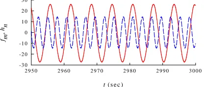
Fig. 4 Cross-flow (solid line) and in-line (dashed line) responses A comparison of cross-flow (fm) and in-line (hn) steady-state responses
due to VIV is displayed in Fig. 4 with Ur≈ 5.385. It can be seen that
the dynamic responses are perfectly periodic, achieving “limit cycles”, with cross-flow amplitudes being greater than in-line amplitudes (Sarpkaya, 2004). The corresponding frequencies are nearly tuned in 2:1 ratio, and there is a clear phase difference between cross-flow and in-line VIV, depending on assigned initial conditions.
Fig. 5 (a) Cross-flow (solid line) and lift force (dotted line) responses; (b) In-line (dashed line) and drag force (dotted line) responses A comparison of riser and associated fluid force responses is displayed in Fig. 5a (cross-flow VIV) and 5b (in-line VIV). A slight phase difference between wake and riser responses occurs more apparently in cross-flow VIV. In any case, the wake displacement parameters (dm,zn)
have greater amplitudes than the riser displacement parameters (fm,hn).
This holds also for the associated velocity parameters (not shown herein), i.e. (em,on) vs. (pm,qn). Overall, Figs. 4 and 5 highlight the
feature of uni-modal wake-riser interaction involving a single response frequency and self-limiting steady response.
Uni-Modal Lock-In Phenomenon
The fundamental lock-in or synchronization phenomenon of SCR in which the uni-modal cross-flow and in-line VIV occur over a wide range of the reduced flow velocity Ur is now highlighted, along with
the predicted maximum response amplitudes A/D. As aforesaid through Eq. 37, Ur can be varied by directly varying either V, ωs or ωm (ωn),
which, in turn, parametrically affects Eqs. 22-29. For the sake of comparison, the results with varying V and system frequencies are presented in Figs. 6 and 8, respectively.
Varying Flow Velocity
In Fig. 6, the flow speed is either increased or decreased in the range 0.1 < V < 0.6 m/s (≈ 3.2x10⁴ < Re < 1.9 x10⁵) with a small increment of 0.01 m/s. Both cross-flow/in-line VIV amplitudes are comparatively plotted vs. Ur. It can be seen that a large-amplitude A/D variation due to
cross-flow (in-line) VIV occurs in between 4 < Ur < 7 (5 < Ur < 6),
with the discontinuity of two response branches owing to a jump phenomenon or hysteresis effect. This highlights the lock-in phenomenon whereby the riser and the fluid are in internally-resonant condition, with the vortex shedding frequency locking into the riser oscillation frequency (Sumer and Fredsoe, 1999). When increasing or decreasing V, overall riser responses are coincident: the sudden jump-down and jump-up critical Ur values are nearly the same, and the
bent-to-right response diagram exhibits a hardening nonlinearity due to the predominant cubic-type restoring forces. The greater response amplitudes – as well as the broader regime of lock-in – correspond to the cross-flow VIV giving rise to the maximum A/D ≈ 1.634, in comparison with maximum A/D ≈ .544 due to in-line VIV. These occur albeit assuming equal empirical properties ( J ≈F, H≈G) for cross-flow and in-line VIV. Overall, the presented theoretical wake-riser t (s e c )
2 9 5 0 2 9 6 0 2 9 7 0 2 9 8 0 2 9 9 0 3 0 0 0
f m
,
hn
-3 0 -2 0 -1 0 0 1 0 2 0 3 0
2 9 1 0 2 9 2 0 2 9 3 0 2 9 4 0 2 9 5 0 2 9 6 0 2 9 7 0 2 9 8 0
f m
,
dm
-5 0 -2 5 0 2 5 5 0
t ( s e c )
2 9 1 0 2 9 2 0 2 9 3 0 2 9 4 0 2 9 5 0 2 9 6 0 2 9 7 0 2 9 8 0
hn
,
z n
-5 0 -2 5 0 2 5 5 0
( a )
( b )
x
0.0 0.2 0.4 0.6 0.8 1.0
N
o
rm
a
li
z
ed
a
m
p
li
tu
d
e
-1.0 -0.5 0.0 0.5 1.0
x
0.0 0.2 0.4 0.6 0.8 1.0
N
o
rm
al
iz
e
d
a
m
p
li
tu
d
e
-1.0 -0.5 0.0 0.5 1.0
horizontal
vertical out-of-plane
[image:5.595.47.272.399.499.2] [image:5.595.51.259.536.625.2]interaction model provides good qualitative agreement with theoretical and experimental literature of cross-flow/in-line VIV, in view of the maximum attainable amplitudes (up to A/D ≈ 2 for flexible cylinders) and the uni-modal lock-in prediction (Blevin, 1990; Sarpkaya, 2004).
Fig. 6 Maximum response amplitudes due to cross-flow (circles) and in-line (stars) VIV with increasing V (filled) or decreasing V (open)
Fig. 7 Comparison of cross-flow VIV with (solid line) and without (dashed line) geometrical nonlinearities
The effect of SCR geometrical nonlinearities on the prediction of cross-flow VIV is now highlighted in Fig. 7, with D = .6 m, ∆≈ 90 and the excited 3rd in-plane mode. The dynamic responses of fm are plotted
corresponding to the Ur at maximum A/D during the lock-in when
increasing V. By considering either linear or nonlinear equations of riser motion (Eqs. 22-25), the comparison reveals a noticeable amplitude and phase difference although both steady-state time histories are based on the same assigned initial conditions. In turn, there is a difference in the relative phase between riser (fm) and wake (dm)
motion. The predicted maximum A/D is about 1.22 (1.48) by linear (nonlinear) model. To circumvent such discrepancies, the geometrical nonlinearities – which indeed play a crucial role in evaluating a new riser equilibrium caused by mean drag – should be accounted for.
Varying System Frequencies
Considering now the fixed v = 0.35 m/s and with this flow speed the potential vortex-excited modes are the same as in Fig. 3. By varying ωs
or ωm (ωn) through the corresponding frequency detuning parameter (σ
or ε) within the range of [-0.8, 0.8], similar response diagrams exhibiting the lock-in phenomenon are obtained in Figs. 8a (cross-flow VIV) and 8b (in-line VIV). The in-line vibration response and the
associated lock-in bandwidth (Fig. 8b) seem to be more sensitive to the frequency variation. Yet, overall achievable amplitudes when varying
ωs or ωm (ωn) are comparable, being approximately equal to those
predicted in Fig. 6 for the varying V case. This similarity of Figs. 6 and 8 may be attributed to that lock-in (4<Ur<7) occurs in the range about
1.3 > ωm/ωs > 0.7 (2.2 > ωn/ωs > 1.7) for cross-flow (in-line) VIV,
rather than being at ωm/ωs =1 (ωn/ωs = 2) or Ur = 5 for stationary riser.
Fig. 8 Maximum response amplitudes due to (a) cross-flow and (b) in-line VIV with varying ωs (filled symbols), ωm and ωn (open symbols)
VIV of SCR vs. TTR
[image:6.595.310.563.160.278.2]A comparison of VIV responses between SCR and TTR having the same flexural tensioned-beam parameter ∆≈ 272 is now highlighted in Fig. 9 with the case of increasing V. From Fig. 2, the potentially excited modes for TTR correspond to the third cross-flow (ωm≈ 1.095 rad/s)
and sixth in-line (ωn≈ 2.194 rad/s) modes, whose shapes are perfectly
symmetric and anti-symmetric with respect to middle span with three and six half-sine waves, respectively.
[image:6.595.42.269.350.454.2]
Fig. 9 Maximum response amplitudes due to (a) cross-flow and (b) in-line VIV: SCR (filled symbols), TTR (open symbols) Based on the same given parameters, empirical coefficients and initial conditions, the response comparison in Fig. 9a highlights that the cross-flow VIV of TTR entails smaller A/D (≈ 1) with respect to the cross-flow VIV of SCR. The lock-in ranges and corresponding response jumps appear similar. Such amplitude difference is attributed to the effect of riser geometry because TTR (SCR) has zero (non-zero) sag and has one (two) displacement component in the cross-flow VIV. The cross-flow amplitudes of TTR tend to be comparable to those of straight spring-mounted cylinders reported in the literature. On the contrary, the in-line VIV amplitudes for both TTR and SCR in Fig. 9b are nearly comparable. Again, this is physically reasonable because the in-line modes of SCR and TTR are the same sixth mode (Fig. 3b) and the in-line VIV of SCR subject to flow normal to the curvature plane is not significantly affected by the riser curvature or sag.
Ur
2 3 4 5 6 7 8 9
A
/D
0.0 0.2 0.4 0.6 0.8 1.0 1.2 1.4 1.6 1.8
Ur
2 3 4 5 6 7 8 9 0.0
0.2 0.4 0.6 0.8 1.0 1.2 1.4 1.6 1.8
(a) (b)
Ur
2 3 4 5 6 7 8 9
A
/D
0.0 0.2 0.4 0.6 0.8 1.0 1.2 1.4 1.6 1.8
Ur
2 3 4 5 6 7 8 9 0.0
0.2 0.4 0.6 0.8 1.0 1.2 1.4 1.6 1.8
(a) (b)
U r
2 3 4 5 6 7 8 9
A
/D
0.0 0.2 0.4 0.6 0.8 1.0 1.2 1.4 1.6 1.8
jum p ph enom enon
t (sec)
1920 1930 1940 1950 1960 1970 1980 1990 2000
f m
[image:6.595.313.564.424.543.2]Influence of Vortex-Excited Modes
It is interesting to understand how the vortex-excited modes having different spatial shapes affect the VIV responses. For a given ∆≈ 272 (see Fig. 2), the cross-flow and in-line VIV modes whose frequency values are in 1:2 ratio are the 1st (2nd, 3rd, 4th,…) in-plane and 4th (6th,
8th, 10th,…) out-of-plane modes, respectively. Note that, due to the SCR in-plane configuration, the spatial shape profiles of odd (1st, 3rd) or even (2nd, 4th) in-plane modes are not perfectly anti-symmetric or symmetric (e.g., Fig. 3a), whereas the spatial shape profiles of even out-of-plane modes are perfectly anti-symmetric (e.g., Fig. 3b). With the same given parameters and empirical coefficients, the analysis of lock-in regime is performed in the case of increasing V, and the maximum A/D results are compared in Table 1 for different potentially-excited modes. Table 1. A comparison of predicted maximum A/D for different excited VIV modes of SCR sample
Cross-flow : In-line
Modes Cross-flow A/D In-line A/D
1 : 4 1.043 0.518
2 : 6 1.634 0.544
3 : 8 1.142 0.564
4 : 10 1.768 0.599
It can be seen that the in-line A/D amplitude tends to slightly increase with the corresponding mode order. This is in contrast to the case of cross-flow VIV, where different excited in-plane modes entail different maximum A/D, depending on the horizontal/vertical shape functions affecting overall coefficients in Eqs 22-29. Again, such difference between cross-flow/in-line VIV is due to the influence of initial sag or curvature of SCR on the in-plane vibration. The even (2nd, 4th) modes seem to be the most dangerous case for this SCR (∆≈ 272) example. Influence of Tensioned-Beam Parameter (Sag/Inclination)
In practical design, the inclinations and sags of SCRs are variable, depending on the geometry (e.g., water depth, horizontal offset, seabed-free length) and the stiffness (e.g., bending and axial rigidity). This influences the beam-cable behaviour of risers. To appreciate the combined effect of riser sag and inclination on the VIV, we now consider three SCRs having different values of water depth YH or
inclination angle θr. With given α≈ 1669, these SCRs have different
[image:7.595.47.276.253.332.2]sag-to-span values and tensioned-beam parameters (∆). For the sake of comparison, the 2nd in-plane (cross-flow) and 6th out-of-plane (in-line) modes are fixed in the VIV analysis of each SCR. With increasing V, the predicted maximum A/D amplitudes during cross-flow and in-line lock-in are comparatively reported in Table 2.
Table 2. A comparison of predicted maximum A/D for different flexible inclined sagged SCRs
θr (deg.) ∆ Sag/span Cross-flow A/D In-line A/D
30 272 0.08 1.634 0.544
45 367 0.10 1.836 0.574
60 615 0.14 1.911 0.624
It can be seen that both maximum cross-flow and in-line amplitudes increase with increasing ∆, increasing θr and increasing sag-to-span
ratio. This highlights that, when the cable behavior (higher ∆) prevails
over the beam behavior (lower ∆), the VIV of SCR becomes more critical. This is physically reasonable because the cable-like (larger sag) SCR is more slender and flexible than the beam-like (lower sag) SCR, potentially leading to larger vortex-induced displacements. This prediction is meaningful as deepwater SCRs tend to behave like marine cables according to the increasing aspect ratio and sag.
Influence of Mass-Damping Parameter
The mass-damping parameter (e.g., SG) plays a very significant role in
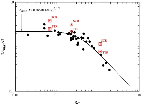
the VIV analysis and prediction (Sarpkaya, 2004) because it affects empirical coefficients, vortex-shedding modes (Williamson and Roshko, 1988) and overall VIV response behaviors. As a matter of fact, many experimental VIV studies of elastically-mounted rigid or long flexible cylinders subject to normal flow depend on the measured mass and damping values. Therefore, it is worth making a comparison of analysis results with a series of experimental data. In this study, we compare the predicted maximum amplitudes during lock-in (Amax/D)
with those gathered by Skop and Balasubramanian (1997), as shown in Fig. 10 which is the so-called Griffin plot (Williamson and Govardhan, 2004). Three SG values (.068, .227, 1.133) are considered for both
SCRs (θr = 30o) and corresponding TTRs, and results of the 2nd (SCRs)
[image:7.595.314.557.320.499.2]and 3rd (TTRs) cross-flow VIV modes are displayed.
Fig. 10 A comparison of predicted cross-flow VIV amplitudes of SCRs and TTRs (crossed squares) with experimental data of spring-mounted cylinders, pivoted cylinders, cantilevers and taut cables (filled circles),
solid line denotes least-squares fit of experimental data Overall, the maximum cross-flow amplitudes of both SCRs and TTRs decrease with increasing SG. This is true if the structural damping or the
structural mass increases (see, e.g., Khalak and Williamson, 1999). It is also worth mentioning that the corresponding in-line VIV response significantly decreases as SG increases and it possibly disappears when
further increasing SG. For TTRs, the predicted Amax/D amplitudes
provide good qualitative, and possibly quantitative, agreement with experimental Amax/D amplitudes. For instance, Moe and Overvik (1982)
considered a riser based on an elastically-mounted rigid cylinder model and reported that, for SG = 0.23, 2Amax/D ≈ 2.18, whereas our study
predicts that, for SG = 0.227, 2Amax/D ≈ 2.17. For SCRs, the inclined
flexible cylinders with sags tend to have greater Amax/D than straight
cylinders such as TTRs, pivoted tubes, cantilevers or taut cables. This prediction needs further experimental confirmation based on real SCR vs. TTR measurement data, with the same controlled SG parameters and
environmental flow conditions.
SG
0.01 0.1 1 10
2
Am
a
x/
D
0.1 1 10
Amax/D = 0.385/(0.12+SG2)1/2
SCR
TTR
SCR
TTR SCR
CONCLUSIONS
A computationally-efficient reduced-order model describing the fluid-catenary riser interaction due to VIV has been developed. The riser model is based on nonlinear equations of 3-D motion of a pinned-pinned beam-cable subject to a steady uniform current flow whose direction is perpendicular to the riser plane of initial equilibrium curvature. The hydrodynamic model is based on the recently-refined nonlinear wake oscillators describing the fluctuating lift/drag forces corresponding to cross-flow/in-line VIV. Overall effects of bending, extensibility, sag, inclination and in-plane/out-of-plane modal coupling are fully taken into account.
A series of parametric studies have been carried out by making use of direct numerical time integrations, which entail nonlinear dynamic responses of marine riser coupled with fluid wake. The spatially and temporally maximum amplitudes due to cross-flow/in-line VIV of risers are predicted, depending on the vortex-excited in-plane/out-of-plane modes. Results highlight the uni-modal lock-in phenomenon when varying the reduced flow velocity parameter, along with some fundamental features of VIV. The comparative analysis of catenary risers and corresponding straight top-tensioned risers has also been performed. Depending on modal shape functions, tensioned-beam (sag/inclination) and system mass-damping parameters, and estimated empirical coefficients, the predicted maximum amplitudes due to cross-flow (in-line) VIV of catenary risers are greater than (nearly comparable to) those of straight risers, due to the influence of initial curvatures of catenary risers. With respect to the cross-flow VIV, the riser amplitude results provide good qualitative agreement with experimental data of rigid/flexible cylinders in the literature. In some cases, the effect of riser geometric nonlinearities is pronounced. Due to the capability of predicting the uni-modal lock-in regime and the associated maximum amplitudes due to cross-flow/in-line VIV, the presented reduced-order hydrodynamics-riser interaction model and analysis may be extended to account for the cases of multi vortex-excited modes, which are theoretically and practically meaningful when the flow is aligned with the catenary riser plane of curvature and/or the flow is spatially sheared. Moreover, the associated development of finite element-based modeling, in conjunction with the improvement of nonlinear wake oscillators based on the computational fluid dynamics, looks very promising.
ACKNOWLEDGEMENTS
The authors gratefully acknowledge the support from the Knowledge Transfer Partnerships (KTP).
REFERENCES
Blevins, RD (1990). Flow-Induced Vibrations, Van Nostrand Reinhold, New York, USA.
Chaplin, JR, Bearman, PW, Cheng, Y, Fontaine, E., Graham, JMR, Herfjord, K, Huera Huarte, FJ, Isherwood, M, Lambrakos, K, Larsen, CM, Meneghini, JR, Moe, G, Pattenden RJ, Triantafyllou, MS, Willden, RHJ (2005). “Blind predictions of laboratory measurements of vortex-induced vibrations of a tension riser,” J Fluids Str, Vol 21, pp 25-40. Currie, IG, Turnbull, DH (1987). “Streamwise oscillations of cylinders near
the critical Reynolds number,” J Fluids Str, Vol 1, pp 185-196.
Hover, F, Davis, JT, Triantafyllou, MS (1997). “Vottex-induced vibration of marine cables: experiments using force feedback,” J Fluids Str, Vol 11, pp 307-326.
Khalak, A, Williamson, CHK (1999). “Motions, forces and mode transitions in vortex-induced vibrations at low mass-damping,” J Fluids Str, Vol 13, pp 813-851.
Kim, WJ, Perkins, NC (2002). “Two-dimensional vortex-induced vibration of cable suspensions,” J Fluids Str, Vol 16, pp 229-245.
Larsen, CM, Halse, KH (1997). “Comparison of models for vortex-induced vibrations of slender marine structures,” Marine Str, Vol 10, pp 413-441. Miliou, A, De Vecchi, A, Sherwin, SJ, Graham, JMR (2007). “Wake dynamics of external flow past a curved circular cylinder with the free stream aligned with the plane of curvature,” J Fluids Mech, Vol 592, pp 89-115.
Moe, G, Overvik, T (1982). “Current-induced motions of multiple risers,” Proc BOSS-82, Behaviour Offshore Str, ed. Chryyostomides, C, Conner, JJ, Vol 1, pp 618-639.
Okajima, A, Nakamura, A, Kosugi, T, Uchida, H, Tamaki, R (2004). “Flow-induced in-line oscillation of a circular cylinder,” European J Mech B/Fluids, Vol 23, pp 115-125.
Ricciardi, G, Saitta, F (2008). “A continuous vibration analysis model for cables with sag and bending stiffness,” Eng Str, Vol 30, pp 1459-1472. Sarpkaya, T (2004). “A critical review of the intrinsic nature of
vortex-induced vibrations,” J Fluids Str, Vol 19, pp 389-447.
Skop, RA, Balasubramanian, S (1997). “A new twist on an old model for vortex-excited vibrations,” J Fluids Str, Vol 11, pp 395-412.
Skop, RA, Griffin, OM (1975). “On a theory for the vortex-excited oscillations of flexible cylindrical structures,” J Sound Vib, Vol 41, pp 263-274.
Srinil, N, Rega, G, Chucheepsakul, S (2007). “Two-to-one resonant multi-modal dynamics of horizontal/inclined cables. Part I: Theoretical formulation and model validation,” Nonlinear Dyn, Vol 48, pp 231-252.
Srinil, N, Rega, G (2007a). “Two-to-one resonant multi-modal dynamics of horizontal/inclined cables. Part II: Internal resonance activation, reduced-order models and nonlinear normal modes,” Nonlinear Dyn, Vol 48, pp 253-274.
Srinil, N, Rega, G (2007b). “The effects of kinematic condensation on internally resonant forced vibrations of shallow horizontal cables,” Int J Nonlinear Mech, Vol 42, pp 180-195.
Sumer, BM, Fredsoe, J (1997). Hydrodynamics around Cylindrical Structures, World Scientific, Singapore.
Triantafyllou, MS, Gopalkrishnan, R, Grosenbaugh, MA (1994). “Vortex-induced vibrations in a sheared flow: a new predictive method,” In Hydroelasticity in marine Technology, Rotterdam, pp. 31-37.
Vandiver, JK (1993). “Dimensionless parameters important to the prediction of vortex-induced vibration of long, flexible cylinders in ocean currents,” J Fluids Str, Vol 7, pp 423-455.
Williamson, CHK (1996). “Vortex dynamics in the cylinder wake,” Annu. Rev. Fluid Mech, Vol 28, pp 477-539.
Williamson, CHK, Govardhan, R (2004). “Vortex-induced vibrations,” Annu. Rev. Fluid Mech, Vol 36, pp 413-455.