City, University of London Institutional Repository
Citation
: Kloukinas, C. and Issarny, V. (2001). SPIN-ning Software Architectures: A
Method for Exploring Complex Systems. In: UNSPECIFIED (pp. 67-76). IEEE Computer
Society. ISBN 0-7695-1360-3
This is the unspecified version of the paper.
This version of the publication may differ from the final published
version.
Permanent repository link:
http://openaccess.city.ac.uk/2898/
Link to published version
: http://dx.doi.org/10.1109/WICSA.2001.948409
Copyright and reuse:
City Research Online aims to make research
outputs of City, University of London available to a wider audience.
Copyright and Moral Rights remain with the author(s) and/or copyright
holders. URLs from City Research Online may be freely distributed and
linked to.
City Research Online:
http://openaccess.city.ac.uk/
[email protected]
S
PIN
-ning Software Architectures:
A Method for Exploring Complex Systems
Christos Kloukinas and Val´erie Issarny
INRIA - Domaine de Voluceau - Rocquencourt
B.P. 105 - 78153 Le Chesnay CEDEX - France
E-mail:
[email protected], [email protected]
Abstract
When designing complex systems that provide multiple non-functional properties, it is usual to try to reuse (and finally compose) simpler existing designs, which deal with each of these properties in solitude. This paper describes a method for automatically and quickly identifying all the different ways one can compose such designs, with the aid of a model checker.
Keywords: architectural composition, architecture trans-formation, architecture discovery, architectural debugging.
1. Introduction
Complex software systems need to provide multiple non-functional properties such as security, reliability, persis-tency, etc.. When designing and building them, it is only logical to try to reuse existing proven designs/solutions for each one of the requested properties [20]. In this way, one can gain both in completion time for a first version of the system and, more importantly, in maintenance efforts later on, since reusable components and general solutions for a particular property tend to be a lot more stable, and errors in them are found and corrected sooner than those built ex-plicitly for a particular system.
This, in particular, is the reason for the growing interest in component based software engineering [4, 8, 29] and in
middleware solutions [18, 22, 25, 26, 30, 31, 36]. Currently
there exists quite a large set of reusable components, often referred to as middleware in the setting of distributed sys-tems, and an equally large set of architectural/design
pat-terns, i.e., of architectures that use such reusable
compo-nents in order to provide a particular property to an applica-tion.
Since no architectural pattern can be expected to provide all the different kinds of properties a real system requires,
the designer must either create a new pattern from scratch or try to reuse existing ones and to compose them. Given the costs in developing a completely new pattern and compo-nents, and the benefits of reuse, it is only regrettable that de-signers have no available methods and tools for easing their task of composing different architectural patterns. Cur-rently, one has to investigate different combinations of so-lutions, e.g.,security solution
i
withreliability solutionj
,in order to find the ones that can best cooperate with each other. In addition, one has to explore the different ways of combining/composing a set of particular designs, since there is more than a single way to compose architectures, when these are indeed composable. This multitude of dif-ferent ways to compose two patterns is due to the fact that middleware/reusable components have general enough in-terfaces, to allow for their reuse in as many different settings as possible. Thus, designers cannot sufficiently constrain the space of possible solutions by taking into account only the interfaces of the various components; not to mention the insufficiency of interfaces to communicate the correct ways one can use a component, see for example [5, 15]. To make things worse, even after having found a set of solu-tions that can indeed cooperate, one has to continue inves-tigating combinations of other existing solutions as well, so as to find the set that optimizes other requirements, such as system throughput, cost of obtaining the required compo-nents, cost of training in-house developers at using them,
etc..
dif-ferent possible solutions should be thoroughly investigated, in order to avoid common fallacies that lead to sub-optimal solutions.
In the following, we present a method for discovering all the possible architectural configurations with which dif-ferent architectural patterns can be composed, i.e., identify the particular bindings between the inputs and outputs of the components of a system, that allow the system to of-fer the properties of all the patterns used. Thus, we show how one can identify sets of existing solutions that can be used together, as well as, all the allowable patterns of use (configurations) for each particular set.
This method can also be used by the designer of a new architectural pattern or reusable component/middleware so-lution, to search for incompatibilities and insufficiencies by trying to compose with other already existing patterns. Thus, problems of architectural mismatch [15] can be iden-tified and corrected early on in the design phase and the development of the specific components can later be based upon more mature models than usual. Since such architec-tural mismatches are the hardest ones to solve when build-ing a system out of reusable components, we believe that this method can help ease (and increase) the application of component based software engineering.
The paper is divided into the following sections: Sec-tion 2 presents the proposed method for composing archi-tectural patterns, Section 3 shows how it can be applied in a more concrete setting, Section 4 discusses some of the issues arising, while Section 5 makes a comparison with related work. Finally, we present our conclusions in Sec-tion 6.
2. A method for composing architectural
pat-terns
When composing two architectural patterns, we have the following information available:
the generic components, i.e., those that a designer can
substitute with components from the application that will make direct use of the pattern. In the patterns themselves, their behavior is left largely unspecified, usually acting just as sources and sinks of data.
The specific components, i.e., those specified in detail
and which correspond to the reusable part of the pat-tern.
The architectural configuration, i.e., the bindings of
input and output ports of the various components.
In order to maximize reuse, we refrain from altering ei-ther kind of components. Thus, the only part of the archi-tectures that we can modify is their configurations, i.e., try
different bindings among the components to obtain a new pattern. This leads to a combinatorial algorithm: if there are
N
components in total, with each one having one in-put and one outin-put port, then we would obtainN
!differentpatterns.
To guide us through this huge number of possible cases, we use the initial configurations as sources of constraints. That is, we only want to construct patterns where by re-moving all the components of the second pattern one would obtain the first pattern and vice versa. Thus the data-flows of the original architectures are preserved, i.e., if a com-ponentAwas directly sending a message to a component
B in one of them, then such a communication link would
also exist in the resulting compositions, possibly with some components of the other architecture being in the middle.
The patterns obtained in this manner do not necessarily provide the property the designer wishes to obtain. There-fore, one must still verify each one independently to find the ones that are indeed useful. The above can be easily au-tomated with the use of a model checker. These are tools that can deal with vast search spaces and, in contrast to the-orem provers, they can be used without requiring much user intervention/guidance. Their primary use is to identify
er-rors in a model, i.e., to expose series of events that can lead
the modeled system in an undesired state, such as deadlock, message loss, out-of-order message reception, etc.. The un-desired behavior/states are symbolically described by the user using some variant of Temporal Logic, such as a linear-time logic (Linear Temporal Logic - LTL) or a branching-time logic (Computational Tree Logic - CTL), see [10] for a comparison of them and [7] for more about model checking.
2.1. Composing with a modeling language
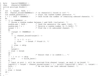
In order to automate the composition process, one has to change the models of the components so that they fol-low a certain set of rules. First, components should com-municate through channels that they receive as arguments at run-time and are not hard-coded into their models, so that it is possible to change them at run-time while trying different configurations. These configurations are created by a new component, hereafter called the Binder; Table 1 shows the code for binding in a random manner. The code in Table 1 stores in the arrayInputsa permutation of the indexes to the channelsarray. Then, we assume a specific ordering of the architectural elements (compo-nents/connectors), e.g., that elementA is element No. 1,
B is No. 2, etc.
. We also assume an ordering of the input and output ports, i.e., channels, of each element, so that we can refer to the ports of elementAas input ports
I
[1n
], and to those ofBasI
[(n
+ 1)(n
+m
)](respec-tively for their output ports
O
[1k
]andO
[(k
+1)l
]),
Table 1. Random binding of input and output ports inPROMELA
1 byte Inputs[CHANNELS] ; 2 chan channels[CHANNELS]; 3 active proctype Binder() 4 {
5 int i, target, UnCh, r ;
6 bit channel_bound[CHANNELS]; /* Is channels[i] bound or not? */ 7 run random_generator() ; /* Start the random number generator. */
8 i = 1 ; UnCh = CHANNELS ; /* UnCh holds the number of remaining unbound channels. */ 9 do
10 :: (i <= CHANNELS) ->
11 /* Choose a random number between 1 and UnCh (inclusive). */
12 random_gen ! UnCh ; /* Send the generator the upper limit. */ 13 random_gen ? r ; /* Receive a random number in [1,UnCh]. */ 14 target = 0 ; /* Find the r-th unbounded channel. */
15 do
16 :: (target <= CHANNELS) ->
17 if
18 :: (! channel_bound[target]) ->
19 if
20 :: (r > 1) ->
r--21 :: else -> break /* Found it. */
22 fi
23 :: else -> skip
24 fi ;
25 target++ 26 :: else -> break 27 od ;
28 if /* Ensure that r is indeed 1... */ 29 :: ( 1 == r) -> skip
30 :: else -> block_here() 31 fi ;
32 /* Input on port i, will be received from channel target; we mark it as bound. */
33 Inputs[i] = target ; channel_bound[target] = 1 ; printf("Inputs[%d] = %d\n", i, target) ; 34 UnCh-- ; /* We now have one less unbound channel. */
35 i++ ;
36 :: else -> break 37 od ;
38 ... 39 }
where
n;m
(respectivelyk;l
) are the number of input (re-spectively output) ports of Aand B. Using these arrays,an element can then access its ports using the expres-sion channels[
O
[element id]]for its output ports andchannels[Inputs[
I
[element id]]]for its input ones.In other words, the
i
thoutput port is always the
i
thchan-nel, while the
i
thinput port is chosen in a non-deterministic wayy
. Finally, after having completed the assignments of channels to input and output ports, the Binder proceeds with spawning the processes that correspond to the architectural elements, to verify the requested property.
As aforementioned, however, the number of configu-rations thus created is
N
!. Therefore, it is evident thatwe must constrain the possible combinations at this stage. Unfortunately, the modeling language of SPIN, PROMELA, does not allow us to easily express the full set of constraints we need. Therefore, we use a weaker set of constraints at this stage: when choosing among channels for an input port, we only consider channels corresponding to output ports of components that belong to the other architecture, or of com-ponents that were directly sending data to that input port in the initial architecture. The changes needed in the code of
y
The interested reader can find out more by visiting html:// www-rocq.inria.fr/˜kloukina/Code/Spin/.
the Binder for this are minimal; it suffices to add an array of booleans, channel_constrained[CHANNELS], which we use right after line 10 in Table 1 to mark, for the current input port, those output ports which are allowed to bind to it. We subsequently use it in line 18 to constrain the choice of channels, by changing the condition to
(! channel_bound[target]) && ! channel_ constrained[target]. Then, for enforcing the full constraints arising from the data-flows in the initial con-figurations, each component should add to messages it is sending, its signature, i.e., a value identifying the particular component. It should also check that the signatures in the messages it is receiving are those of the components that “preceded” it in its initial architectural pattern and only those. In this way, if a component receives a message that has not passed through all the components that were supposed to treat it in its initial architecture, or that has passed from some component(s) that should not have treated it yet, then the signatures will be incorrect and so we can dismiss this as an invalid composition of the two configurations.
Finally, when composing architectural patterns Arch 1
withArch 2 (
Arch 1
Arch
2), we must take into
outputs and thus multiple paths are formed after it. Then it may be the case that, for the composition to work, one needs to introduce components fromArch
2 in more than
one of these paths, so that the property provided by the sec-ond pattern holds for all of them. To be able to do so we calculate the degree of multiplicity (()) of Arch
1, i.e.,
the sum of the number of outgoing connections, over the components ofArch
1that have multiple outgoing
tions, or 1 if all components have a single outgoing connec-tion. Then, we provide the model checker with the compo-nents ofArch
1and (Arch
1
)copies of the components of Arch
2. This allows us to have enough components of the
second architecture available for placing them at the differ-ent paths. These copies are handled specially by the Binder, in the sense that they are the only ones allowed to receive input from themselves, effectively removing them from the rest of the system when they are not really needed.
When executing the model, the Binder will randomly pick a configuration and then start the rest of the compo-nents. When it starts a component it passes to it as argu-ments the channels from which it will receive input and those to which it will send output.
By asking a model checker to verify that the property required never holds, i.e.,:E:bound^
A(bound^
p
)where
p
is the property we want our system to provide, we can force it to report to us the exact configurations (if any) for which it does indeed hold, that is, find a path (E) where,after () having bound the components,
p
always holds ()for all paths (A).
From the above discussion, it is evident that we are as-suming an order among the architectures to be composed. This order is given by the user and is needed for two rea-sons: first, for knowing whether to consider (Arch
1 )
copies ofArch
2or vice-versa and, secondly and most
im-portantly, for knowing that we will be using the generic components ofArch
1 and not those of Arch
2. This latter
information is needed since we are constraining the bind-ings of the generic components as well, just as we are doing for the specific ones.
3. Experiment
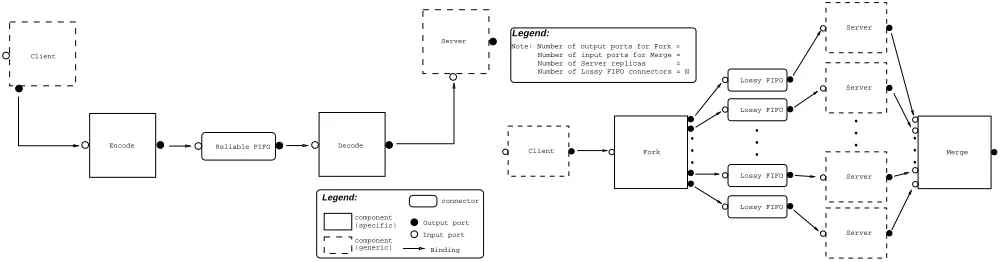
In this section we describe how one can apply the com-position method on two particular architectural patterns. These were chosen because of their relevance to middle-ware architectures. The first pattern provides secure com-munication between a client and a server by using pairs of encoders/decoders (hereafter referred to as Encode-Decode - see Fig. 1(a)). It is a classic example of a middleware architecture, effectively implementing a network stack just like a CORBA ORB does. The second architectural pat-tern provides reliability for an application server and a com-munication medium by replicating them and introducing a
component that forks (multicasts) the client’s requests to the server replicas over an unreliable medium and a com-ponent that merges the replicas’ replies and returns a re-sult to the client (hereafter referred to as Fork-Merge - see Fig. 1(b)). Even though this one deviates from the clas-sic network stack paradigm, it is of particular importance to distributed systems, since their complexity is partially due to the possibility of communication/component faults. Additionally, it is a pattern whose configuration contains components with multiple outputs and thus allows us to test our method with a pattern whose degree of multiplicity is greater than one.
In the case of Fork-Merge, only Fork has multiple outgo-ing connections, so(Fork-Merge)=
N
, i.e., the numberof the Fork component’s outgoing connections. In Encode-Decode no component has multiple outgoing connections, so its degree of multiplicity is equal to1.
Both patterns were validated with respect to the property that all messages sent by the client are eventually received (and in the correct order) by the server (or at least by one of them in the case of Fork-Merge). This non-lossy, FIFO receipt of messages has different meanings for each one of the architectures; for Encode-Decode it means that the en-coding of messages works correctly, while for Fork-Merge that the system is fault-tolerant (up to a certain number of faults).
The property that we want the composed patterns to pro-vide is the conjunction of the two initial properties. Even though the wording of the property remains the same, its meaning now is that the system will be both secure (at some parts of it) and fault-tolerant (at some parts of it). To simplify the property and the model, we removed the clients and the servers altogether and replaced them with
Env sourceandEnv sink. The former provides a data stream to test the pattern against and the latter consumes the data stream at the end and checks the signatures of the messages to assure that all components of both architec-tural patterns have been used. This is the same as if we had left the clients and servers in the model and consid-ered the Env sourceandEnv sink processes as non-obstructive observers right after the client and right after the last component. Thus, the property becomes that all mes-sages sent fromEnv sourcewill be eventually received (and in the correct order) byEnv sink. For this kind of property it suffices that messages can take three distinct val-ues [2, 39], which allows us to validate the model without suffering from state explosion due to the infinitely possi-ble values a message may take. So given the three different message types white, red and blue, the property
p
is: (sentred ) receivedred) ^ :(:receivedredU
receivedblue)
(1)
Reliable FIFO
Binding Input port Output port
connector component
(generic) component (specific) Encode Decode Client
Server
Legend:
(a) Encode-Decode: A pattern for secure communication in a client-server system
Client
...
Fork
...
Merge Server
Server
Server Server
...
Lossy FIFO Lossy FIFO
Lossy FIFO Lossy FIFO
...
Note: Number of output ports for Fork = Number of Lossy FIFO connectors = N Number of Server replicas = Number of input ports for Merge =
Legend:
[image:6.612.55.555.66.197.2](b) Fork-Merge: A pattern for augmenting the reliability of a server and a communication medium in a client-server system
Figure 1. Two software architectural patterns
second demands that blue messages are received after red ones which is the FIFO order, since they are emitted in that order.
The model checker we are using is SPIN [16, 17, 35] which was specifically developed for the verification of asynchronous models, as are the middleware architectures we are interested in; it is freely available and attracts interest from a large group of researchers. The particular features of SPINthat make it interesting for our method is its support of channels, its ability to report all the errors in a model and not just the first one, as well as the resemblance of its mod-eling language, PROMELA, to a programming language.
SPIN is used by providing a model of the system in PROMELA, as well as a formula in LTL that codifies er-roneous behaviors of the system. Then it checks that the different behaviors/traces the model can produce do not be-long to the erroneous ones.
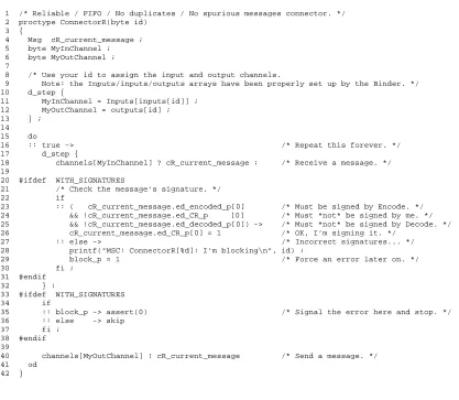
Table 2 shows the model of the reliable FIFO connec-tor component of the Encode-Decode architecture as it was used in this experiment. Lines 8–13 show the passing of in-put/output channels at run-time to the component and lines 20–31 and 33–38 the checking of signatures.
Both orderings for the composition of the architectures were considered in the experiment, i.e., Fork-Merge
Encode-Decode as well as Encode-DecodeFork-Merge.
Each composition was done in two phases. In the first, we used the Binder component to identify all different con-figurations of the available components and in the second we verified each one of those with respect to
p
(see prop-erty (1)) to obtain the solutions. The reason for which we did not verify the models against:E:bound^
A(bound^
p
)but did a two step verification, is that SPINdoes notsupport branching-time temporal formulæ. If we had tried to verify them against : (:bound ^
(bound ^
p
)),then SPIN would have reported all the different traces for which
p
always holds for each configuration, which arein-finitely many. Note, however, that a method was proposed in [38] for allowing SPINto verify CTL* formulæ, which is a superset of both LTL and CTL.
In the first phase, we obtained 90 different configura-tions for Fork-MergeEncode-Decode, down from12!=
479001600 z
which we would get if Binder did not use constraints. For Encode-DecodeFork-Merge the initial
9!=362880 x
configurations were reduced to just 28 in the first phase.
For the second phase, we remarked that while SPIN man-aged to reveal problems in configurations that are invalid quite quickly (usually in less than 3 seconds), it needed about 3 hours to validate the correct ones. Therefore, we first run SPINon each of the configurations with a timeout of 1 minute and then collected the cases that had not fin-ished and verified them all together, which thanks to SPIN’s partial-order reduction took about the same time.
The 90 different configurations for Fork-Merge
Encode-Decode were obtained in less than 4 seconds. Us-ing the 1 minute timeout, we retrieved 5 cases in 21 minutes which we subsequently verified in 3 hours and 10 minutes. The 28 configurations for Encode-Decode Fork-Merge
were obtained in less than 6 seconds. Then, we retrieved 4 cases in 8.5 minutes and verified them in 2 hours and 48 minutes. Thus, the time for obtaining 9 different solutions was 29.5 minutes and another 5 hours and 58 minutes were needed to fully verify them.
Some of the obtained solutions are shown in Fig. 2. Components of Encode-Decode are drawn using boxes, those of Fork-Merge using ellipses andEnv sourceand
Env sink using trapeziums. The Encode 2 and
De-z
We haveEnv source,Env sink,N Encoders,NDecoders,N reliable Connectors, 2 lossy Connectors, Fork and Merge, for a total of 12 components, whenN=2as was the case in this experiment.
x
Table 2. A reliable FIFO connector modeled in Promela
1 /* Reliable / FIFO / No duplicates / No spurious messages connector. */ 2 proctype ConnectorR(byte id)
3 {
4 Msg cR_current_message ; 5 byte MyInChannel ; 6 byte MyOutChannel ; 7
8 /* Use your id to assign the input and output channels.
9 Note: the Inputs/inputs/outputs arrays have been properly set up by the Binder. */ 10 d_step {
11 MyInChannel = Inputs[inputs[id]] ; 12 MyOutChannel = outputs[id] ; 13 } ;
14 15 do
16 :: true -> /* Repeat this forever. */
17 d_step {
18 channels[MyInChannel] ? cR_current_message ; /* Receive a message. */ 19
20 #ifdef WITH_SIGNATURES
21 /* Check the message’s signature. */
22 if
23 :: ( cR_current_message.ed_encoded_p[0] /* Must be signed by Encode. */ 24 && !cR_current_message.ed_CR_p [0] /* Must *not* be signed by me. */ 25 && !cR_current_message.ed_decoded_p[0]) -> /* Must *not* be signed by Decode. */ 26 cR_current_message.ed_CR_p[0] = 1 /* OK, I’m signing it. */
27 :: else -> /* Incorrect signatures... */
28 printf("MSC: ConnectorR[%d]: I’m blocking\n", id) ;
29 block_p = 1 /* Force an error later on. */
30 fi ;
31 #endif 32 } ;
33 #ifdef WITH_SIGNATURES
34 if
35 :: block_p -> assert(0) /* Signal the error here and stop. */ 36 :: else -> skip
37 fi ; 38 #endif 39
40 channels[MyOutChannel] ! cR_current_message /* Send a message. */ 41 od
42 }
code 2 components in Fig. 2(b) are shown short-wired because they are not really supposed to be used by the ar-chitecture; these are the second copies of theEncodeand
Decodecomponents due to Fork-Merge’s degree of multi-plicity which throughout the experiment was assumed to be 2.
We should note here that for larger architectural patterns than the two used in this experiment, a model checker may be unable to cover all the candidate configurations in phase one of this method. One solution to this problem is to add additional pseudo-constraints for some components. That is, assume that component
c
i
cannot receive input from componentsc
j
;c
k
and in subsequent runs change these con-straints, i.e., allow it to receive input fromc
j
;c
k
but disal-low it to receive input fromc
l
;c
m
, where allj;k;l;m
are different.4. Discussion
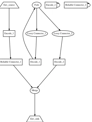
The configurations obtained from the first phase could be diminished even further, if we could use the whole ini-tial connection graphs to constrain the configurations ob-tained, by insisting that a component has before it in a path
all the components it had in its initial architecture and in the correct order. However, this is not easy to program us-ing PROMELA. That is why we chose to use a weaker set of constraints, which allow the creation of some completely strange and obviously wrong configurations, e.g., see Fig. 3.
In parallel to this work, we are working on a method which uses the initial connection graphs to create the differ-ent configurations that are then verified with SPIN[21], thus removing SPIN from phase one of this architectural iden-tification method. By using all the structural information contained in the initial configurations, we are trying to cre-ate candidcre-ate configurations that already adhere to all of the constraints discussed so far. This would allow us to remove the current first phase and to dispense with the imposed con-straints altogether, those of the first phase evidently, as well as those in the form of signatures. Thus the state space of the models would be reduced and the verification of the can-didate configurations with respect to the required property would be sped up even further.
Env_source
Fork
Env_sink Encode_1
Reliable Connector_1
Encode_2
Reliable Connector_2
Decode_1
Merge Decode_2 Lossy Connector_1 Lossy Connector_2
(a)
Env_source
Encode_1
Env_sink Fork
Encode_2
Decode_1
Decode_2
Reliable Connector_1
Merge
Reliable Connector_2 Lossy Connector_1 Lossy Connector_2
[image:8.612.102.230.64.511.2](b)
Figure 2. Two of the solutions for Fork-Merge
Encode-Decode
also the question of how to merge the different data tures used by the initial architectures to obtain data struc-tures that can be used by a combined architecture.
In this experiment, both architectures used the same ab-straction technique to map the possibly infinite values of a message to just three distinct values, which made it possible to easily verify the FIFO reception of data without suffering from state explosion.
As far as the data structures are concerned, we were able to just glue them together, thus having messages where one part of them was processed only from components of the Encode-Decode architecture, while the other was processed
Env_source
Encode_1
Env_sink Reliable Connector_1
Encode_2
Decode_1 Fork
Decode_2
Merge
Reliable Connector_2
[image:8.612.353.505.69.270.2]Lossy Connector_1 Lossy Connector_2
Figure 3. One of the (wrong) configurations obtained from phase one
by Fork-Merge’s components. This was the reason (plus the rather na¨ıve model of Merge) why we obtained solu-tions like the one shown in Fig. 2(b) where Merge (and the fictitious Servers before it) are assumed to be processing en-coded messages (the decoding of these is done just after the merging of the Servers’ replies). Even though the validity of such a solution can be defended theoretically, see for ex-ample [1] for a discussion of processing encoded data, it is something rarely expected to be seen in practice and a sign that the model(s) of some component(s) does not closely reflect reality.
It is therefore quite possible that one would have to do a considerable amount of work in order to bring both initial architectures at the same level of abstraction before com-posing them. The resulting state space might, however, be substantially big for a tool to check it all; automatic model abstraction [6, 14, 33, 37] and/or model slicing [27] may prove to be quite helpful in that case.
However, in the case of middleware architectures such as those proposed by the CORBA Services [30, 31], we ex-pect the models of the different architectures to be using a rather common set of abstractions, making them easier to compose. In fact, we believe that the (possible FIFO) even-tual reception of data suffices as a validation property for most of the middleware architectural patterns. Indeed, in the aforementioned experiment, Fork-Merge used this property to express that the pattern provided reliable communication, while Encode-Decode used the same property for express-ing secure communication.
mes-sage types and a small set of properties one should verify, thus causing the models of the components of these patterns to be at equivalent abstraction levels.
Finally, we should mention that this method could also be used for creating more reusable architectures. This can be achieved by trying to compose an architecture with exist-ing, more or less standard, architectures. Then, by studying the possible solutions obtained and even more importantly, the expected but not obtained solutions, one can identify the particular points of the architecture that caused these in-compatibilities and correct the architecture early on in the design phase, before even having started to implement its components. This way one can avoid unpleasant surprises having to do with incompatible components and communi-cation protocols. In the example mentioned, one would thus be incited to rework the models of the components so as to disallow results such as the one shown in Fig. 2(b).
5. Related work
To the best of our knowledge, the computation of com-posite configurations has not been examined in the past. Related work is mainly concerned with the composition of software systems at the specification level, hence leaving few opportunities for automating the process. The work that is the most related to ours is [28]. There, two complemen-tary kinds of composition were identified: vertical and
hor-izontal. The former relates to the top-down refinement
pro-cess. Horizontal composition is used to compose instances of architectures to form one large composite architecture. It is handled by the developer on a case-by-case basis ac-cording to a simple syntactic criterion, e.g., the composed architectures can share only components.
From the perspective of identifying a middleware con-figuration meeting application requirements, vertical com-position serves refining those requirements into a concrete middleware configuration. This is the approach that is actu-ally used in the Aster project [3] for promoting design and
software reuse by allowing the systematic construction of
customized middleware systems that are shown to match an application’s nonfunctional requirements. However, verti-cal composition falls short when applications require dif-ferent types of non-functional properties, as already sug-gested by the case-by-case approach to horizontal composi-tion proposed by Moriconi et al..
In the work appertained to software development pro-cesses, one finds multiple architectural views of software systems, each one addressing a concern of one of the var-ious stake-holders (e.g., end-users, managers, developers). In this direction, we find the work of [23] that introduces the “4+1” views of a software system architecture. The four system views (logical, process, development and phys-ical) are then loosely linked together through use-case
sce-narios (i.e., the “+1” view). Multiple-view descriptions of a software system were also considered in [12, 13]. This area of research work relates to ours in that it is concerned with the decomposition of the system’s software specifica-tion in terms of various architectural views. However, the architectural views we consider are at a higher level of de-sign, and all relate to the middleware architectural styles un-derlying the execution of distributed applications. Specifi-cally, the software system “views” we focus on prescribe the middleware configurations to be used for enforcing given types of non-functional properties, which is to be composed with similar “views”. In general, our work is complemen-tary to the above references in that it offers methods and tools for helping the designer in reusing existing middle-ware platforms for the design of a softmiddle-ware system com-plying with the architectural views that are set up during the design phase and that integrates non-functional consid-erations (e.g., the process and physical views in the “4+1” views approach).
Composing components offering various properties (or
features) has also been investigated in [40] for the specific
case of telecommunication applications, where components can be assembled according to the pipe-and-filter architec-tural style. Even though features are usually self-contained and independent from the others, inconsistencies do arise and these are left to be resolved by the developer. Our context, however, is broader and cannot be reduced to sim-ple horizontal compositions chaining middleware configu-rations. In fact, pipe and filter compositions rarely appear to be middleware compositions of much interest.
Finally, we should mention [24] where the authors dis-cuss the unification of architectural fragments. In contrast to our method, they are able to unify similar components be-tween different architectures, even when these are partially defined. However, in the kind of patterns we are consider-ing, i.e., fully described reusable-specific components plus partially defined generic components (called real compo-nents/placeholders respectively in that work), it is unclear whether they can obtain similar results, i.e., different inter-weavings of the components of the two architectures.
6. Conclusions
Designing complex systems demands the use of many kinds of architectural patterns in order to provide the multi-ple non-functional properties these systems require. These different architectural patterns cannot be used in isolation but must be composed together and collaborate.
it to automatically obtain all possible compositions of two architectures in less than 30 minutes.
In addition, it can be used to early debug and guide the architecture development process of highly reusable com-ponent solutions that are to be used along with already ex-isting middleware solutions.
We are currently working on substituting the process of identifying candidate solutions (which we later on verify to ascertain that they indeed provide the requested properties) by a graph-based algorithm that fully utilizes the structural information of the architectures that we want to compose,
i.e., their configurations, so that we can substitute the rather
na¨ıve combinatorial method used now. That would highly reduce the cases passed on to verification and speed up the verification itself since now we could dispense with the sig-natures on the messages currently needed to discard cases. It would also highlight some cases where the models of the components do not allow a certain utilization, even though it is meaningful from a structural point of view, which may sometimes be a reason to revise the models themselves.
Acknowledgments: This work is partially funded by the
IST DSoS{
research project. The authors would also like to acknowledge the help provided by Dr. Apostolos Zarras and the anonymous reviewers at WICSA2001 through their criticism and suggestions for improvement.
Figures 2 and 3 were created by the tool Dot from AT&T Labs’ Graphviz packagek
.
References
[1] M. Abadi, J. Feigenbaum, and J. Kilian. On Hiding Infor-mation from an Oracle. Journal of Computer and System
Sciences, 39(1):21–50, 1989.
[2] S. Aggarwal, C. Courcoubetis, and P. Wolper. Adding
Live-ness Properties to Coupled Finite-State Machines. ACM
Transactions on Programming Languages and Systems,
12(2):303–339, 1990.
[3] Aster project. Aster project’s Home Page,
Soli-dor group, INRIA-Rocquencourt. [Online] Available
athttp://www-rocq.inria.fr/solidor/work/
aster.html[2001, Feb. 2]., 2001.
[4] A. W. Brown and K. C. Wallnau. The current state of CBSE.
IEEE Software, 15(5):37–46, Sept./Oct. 1998.
[5] M. B¨uchi and W. Weck. A Plea for Grey-Box Components. In G. T. Leavens and M. Sitaraman, editors, Proceedings of
the First Workshop on the Foundations of Component-Based Systems, Zurich, Switzerland, September 26 1997, pages
39–49, Sept. 1997. Also available athttp://www.cs.
iastate.edu/˜leavens/FoCBS/index.html.
{
DSoS project home page: http://www.newcastle. research.ec.org/dsos
k
Graphviz’s home page: http://www.research.att.com/ sw/tools/graphviz/
[6] E. Clarke, O. Grumberg, S. Jha, Y. Lu, and H. Veith. Counterexample-Guided Abstraction Refinement. In Emer-son and Sistla [11], pages 154–169.
[7] E. Clarke, Jr., O. Grumberg, and D. Peled. Model Checking. MIT Press, Cambridge, MA, 2000.
[8] P. C. Clements. From Subroutines to Subsystems:
Component-Based Software Development. The
Amer-ican Programmer, 8(11), Nov. 1995. Also available
fromhttp://www.sei.cmu.edu/publications/
articles/cb-sw-dev.html. This journal is now called “The Journal of Information Technology
Manage-ment”, and can be found athttp://www.cutter.com/
itjournal.
[9] D. Dams, R. Gerth, S. Leue, and M. Massink, editors.
Theoretical and Practical Aspects of SPIN Model Check-ing - 5th and 6th International SPIN Workshops, volume
1680 of Lecture Notes in Computer Science, Trento, Italy & Toulouse, France, July & Sept. 1999. Springer-Verlag. Also
available from http://link.springer.de/link/
service/series/0558/.
[10] E. A. Emerson and J. Y. Halpern. “Sometimes” and “Not Never” Revisited: On Branching versus Linear Time Tem-poral Logic. Journal of the ACM, 33(1):151–178, Jan. 1986. [11] E. A. Emerson and A. P. Sistla, editors. Computer Aided
Verification - 12th International conference, CAV 2000,
vol-ume 1855 of Lecture Notes in Computer Science, Chicago, IL, USA, July 2000. Springer-Verlag.
[12] A. C. W. Finkelstein, D. M. Gabbay, A. Hunter, J. Kramer, and B. Nuseibeh. Inconsistency handling in multiperspec-tive specifications. IEEE Transactions on Software
Engi-neering, 20(8):569–578, Aug. 1994.
[13] P. Fradet, D. Le M´etayer, and M. P´erin. Consistency check-ing for multiple view software architectures. In Proceedcheck-ings
of the joint 7th European Software Engineering Conference (ESEC) and 7th ACM SIGSOFT International Symposium on the Foundations of Software Engineering (FSE-7),
Lec-ture Notes in Computer Science, Toulouse, France,
Septem-ber 1999. Springer-Verlag. Also available fromftp://
ftp.irisa.fr/local/lande/.
[14] M.-d.-M. Gallardo and P. Merino. A Framework for Auto-matic Construction of Abstract Promela Models. In Dams et al. [9], pages 184–199.
[15] D. Garlan, R. Allen, and J. Ockerbloom. Architectural
Mismatch or Why it’s Hard to Build Systems out of Existing Parts. In Proceedings of the 17th International
Conference on Software Engineering, pages 179–185, Apr.
1995. Also available fromhttp://www.cs.cmu.edu/
afs/cs.cmu.edu/project/able/www/paper_ abstracts/archmismatch-icse17.html.
[16] G. J. Holzmann. Design and Validation of Computer
Protocols. Prentice-Hall, Englewood Cliffs, N.J., 1991.
Also available from http://cm.bell-labs.com/
cm/cs/what/spin/Doc/Book91.html.
[17] G. J. Holzmann. The Spin Model Checker. IEEE
Transactions on Software Engineering, 23(5):279–295, May
1997. Also available from http://cm.bell-labs.
[18] IBM Corporation. MQSeries Version 5. [Online]
Available at http://www-4.ibm.com/software/
ts/mqseries/v5/[2000, Mar. 4], Mar. 2000.
[19] ISAW98 - Proceedings of the 3rd International Software
Ar-chitecture Workshop, Orlando, FL, USA, Nov. 1998.
[20] V. Issarny, T. Saridakis, and A. Zarras. Multi-View Descrip-tion of Software Architectures. In ISAW [19], pages 81–84. Also available from [3].
[21] C. Kloukinas and V. Issarny. Automating the Composition of Middleware Configurations. In Proceedings of the 15th
IEEE International Conference on Automated Software En-gineering (ASE-2000), pages 241–244, Grenoble, France,
Sept. 2000. Also available from http://www-rocq.
inria.fr/solidor/doc/doc.html.
[22] D. Krieger and R. M. Adler. The Emergence of Distributed Component Platforms. Computer, 31(3):43–53, Mar. 1998.
[23] P. B. Kruchten. The 4+ 1 View Model of
Architec-ture. IEEE Software, 12(6):42–50, Nov. 1995. Also
available from http://www.rational.com/uml/
resources/whitepapers/dynamic.jtmpl? doc_key=350.
[24] R. Melton and D. Garlan. Architectural Unification. In
Proceedings of CASCON’97, Ontario, Canada, Nov. 1997.
Also available from http://www.cs.cmu.edu/
afs/cs.cmu.edu/project/able/www/paper_ abstracts/unification.html.
[25] Microsoft Corporation. COM: Technical Overview.
[Online] Available athttp://www.microsoft.com/
com/wpaper/[2001, Mar. 14], Mar. 2001.
[26] Microsoft Corporation. DCOM: Technical Overview.
[Online] Available athttp://www.microsoft.com/
com/wpaper/[2001, Mar. 14], Mar. 2001.
[27] L. I. Millet and T. Teitelbaum. Slicing Promela and its Ap-plications to Model Checking, Simulation, and Protocol Un-derstanding. In 4th International SPIN Workshop, pages 70–
78, Paris, France, Nov. 1998. Also available fromhttp:
//netlib.bell-labs.com/netlib/spin/ws98.
[28] M. Moriconi, X. Qian, and R. Riemenschneider. Correct Architecture Refinement. IEEE Transactions on Software
Engineering, 21(4):356–372, Apr. 1995. Also available
from http://www.csl.sri.com/dsa/publis/
tse95.ps.gz.
[29] O. Nierstrasz, S. Gibbs, and D. Tsichritzis. Component-Oriented Software Development. Comm. ACM, 35(9):160– 165, Sept. 1992.
[30] Object Management Group. The Common Object
Re-quest Broker: Architecture and Specification - Revision
2.3.1. [Online] Available at http://cgi.omg.org/
library/c2indx.html [2001, Mar. 14], Oct. 1999.
Documentformal/99-10-07.
[31] Object Management Group. CORBA Services.
[Online] Available at http://www.omg.org/
technology/documents/formal/corba_
services_available_electro.htm [2001,
Mar. 14], Oct. 2000.
[32] POPL86 - 13th ACM Symposium on Principles of
Program-ming Languages, St. Petersburg Beach, FL, USA, Jan. 1986.
[33] J. Rushby. Integrated Formal Verification: Using Model
Checking with Automated Abstraction, Invariant Genera-tion, and Theorem Proving. In Dams et al. [9], pages 1–11.
[34] SPIN98 - 4th International SPIN Workshop, Paris, France,
Nov. 1998. Also available from http://netlib.
bell-labs.com/netlib/spin/ws98.
[35] SPIN’s Home Page. URL: http://netlib.
bell-labs.com/netlib/spin/whatispin. html, 2000.
[36] SUN Microsystems. Enterprise JavaBeans
Technol-ogy. [Online] Available at http://java.sun.com/
products/ejb[2001, Mar. 14], Mar. 2001.
[37] M. Vaziri and G. Holzmann. Automatic Generation of
Invariants in SPIN. In SPIN [34], pages 124–133.
Also available from http://netlib.bell-labs.
com/netlib/spin/ws98.
[38] W. Visser and H. Barringer. CTL* Model
Check-ing for SPIN. In SPIN [34], pages 32–51. Also
available from http://netlib.bell-labs.com/
netlib/spin/ws98.
[39] P. Wolper. Expressing Interesting Properties of Programs
in Propositional Temporal Logic (extended abstract). In
POPL86 [32], pages 184–193.
[40] P. Zave and M. Jackson. A component-based approach to telecommunication software. IEEE Software, XV(5):70–78,
September/October 1998. Also available fromhttp://