SIMULATIONS OF RAREFIED AND CONTINUUM HYPERSONIC FLOW OVER
RE-ENTRY OBJECTS
Thomas J Scanlon (1), Rodrigo C Palharini (2), Craig White (3), Daniel Espinoza (4), Vincent Casseau (5) (1) Centre for Future Air-Space Transportation Technology, Department of Mechanical and Aerospace
Engineering, University of Strathclyde, Glasgow G1 1XJ, UK: [email protected]
(2) Institute of Aeronautics and Space, Division of Aerodynamics (DCTA/IAE/ALA), Praça Mal. Eduardo Gomes, 50, 12228-904, São José dos Campos – SP – Brazil: [email protected]
(3) School of Engineering, Division of Aerospace Sciences, James Watt South Building, University of Glasgow, Glasgow G12 8QQ, UK: [email protected]
(4) Centre for Future Air-Space Transportation Technology, Department of Mechanical and Aerospace Engineering, University of Strathclyde, Glasgow G1 1XJ, UK: [email protected]
(5) Centre for Future Air-Space Transportation Technology, Department of Mechanical and Aerospace Engineering, University of Strathclyde, Glasgow G1 1XJ, UK: [email protected]
ABSTRACT
Numerical simulations of high-speed, high-altitude flow over re-entry objects have been carried out for a variety of flow conditions corresponding to test cases proposed for the 1st Spacecraft Demise Workshop. In the continuum regime, conventional computational fluid dynamics (CFD) has been employed to characterise the aerothermodynamic loads acting on the bodies and to predict the shock structures in the surrounding flow fields. In the upper atmosphere, transition-continuum regime the direct simulation Monte Carlo (DSMC) approach has been applied using the quantum-kinetic (Q-K) chemistry model to account for the dissociation of nitrogen. Both CFD and DSMC approaches have been applied within the framework of the open-source CFD toolbox OpenFOAM.
1. INTRODUCTION
As spacecraft enter and traverse a planetary atmosphere, they may encounter widely varying flow regimes. The rarefied flow at high altitudes may be characterized by low density and thermochemical non-equilibrium while, after a transition zone, the spacecraft will encounter continuum flow where conventional Computational Fluid Dynamics (CFD) can be utilized. In both flow regimes, the gas environment is characterised by a detached bow-shock upstream of the body followed by a high temperature region immediately downstream of the shock. In this searingly hot region, chemical reactions may take place involving dissociation, exchange and ionization while surface chemistry is also possible.
1.1 Rarefied Gas Flows
The extent of gas rarefaction is traditionally gauged by a parameter known as the Knudsen number, Kn, defined
as the ratio of the mean free path of the gas molecules to a characteristic length scale of the vehicle. As the Knudsen number increases, the non-continuum, particulate-like behaviour of the gas becomes more important. In highly rarefied environments (Kn > 0.1) accommodation of the thermochemical non-equilibrium effects that occur in the flow away from surfaces remains a challenging problem. For this reason, analysis of gas flows in the non-continuum regime is most naturally conducted using specialised computational techniques that are derived from a statistical mechanical representation of the behaviour of the individual particles comprising the flow.
1.2 Continuum Gas Conditions
Conventional Computational Fluid Dynamics (CFD) solutions become appropriate as Kn decreases (Kn < 0.1) and the linear relationships between stress-rate of strain and heat flux-temperature gradient are re-established in the continuum flow. Once more, the OpenFOAM CFD code has been adopted for the simulations of high-speed compressible flow and the capture of the detached and attached shock structures evident in the flow field. Specifically, the OpenFOAM compressible solver called rhoCentralFoam [6] has been employed. This solver uses semi-discrete, non-staggered, Godunov-type central [7] and central-upwind [8] schemes, with these schemes being based on the exact evolution and averaging over Riemann fans such that the requirement for a Riemann solver is avoided, resulting in simple, efficient and universal schemes [8]. The rhoCentralFoam solver has been validated successfully against various analytical solutions [9].
2. METHODOLOGY
2.1 DSMC Studies
[image:2.595.312.538.320.540.2]The algorithm for a DSMC computation is shown in Fig. 1.
Figure 1. DSMC algorithm.
A summary of this algorithm would be as follows; create an initial particle distribution based on the macroscopic free-stream density, temperature and velocity. Next, particle fluxes are introduced at inlets and outlets based on the free-stream conditions. The DSMC particles are then streamed ballistically,
followed by the processing of collisions, wall interactions and chemical reactions. Steady-state conditions are assumed when the number of particles in the system and the global particle kinetic energy are invariant with time. At this point, we begin the time-averaging process to build up a statistical picture of the flow-field. Following a sufficient number of samples, we may then derive macroscopic fields such as density, velocity and temperature from a knowledge of the time-averaged microscopic fields of mass, momentum and energy.
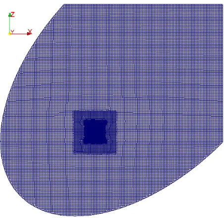
Space discretisation is carried out in a similar manner to that of conventional CFD using a computational mesh. However, good DSMC practice dictates that individual cell sizes should be a fraction of the gas mean-free path, while the time-step magnitude should be less than the mean-free time. Generation of the computational mesh has been executed using the OpenFOAM meshing utility snappyHexMesh and is shown in Figs. 2, 3 and 4 for the case of 45o flow over a hollow cylinder.
[image:2.595.92.249.375.633.2]Figure 2. Overall dsmcFoam computational mesh.
[image:2.595.343.509.571.699.2]Figure 4. Surface mesh on the hollow cylinder.
Tab. 1 shows the free-stream conditions for all of the rarefied gas, DSMC cases.
Parameter Value
Mach number (Ma) 24.64
Velocity (V∞) 7364 m/s
Temperature (T∞) 222 K
Pressure (p∞) 0.00749787 Pa
Density (ρ∞) 1.18!10-7kg/m3
Mass fraction N2 (mN2) 1.0
Mass fraction O2 (mO2) 0.0
[image:3.595.325.524.81.290.2]Wall temperature (Tw) 200 K
Table 1. Free-stream conditions for the DSMC cases.
Half-symmetry conditions were employed for the 45o case, while a quarter-symmetry mesh was used for the 0o and 90o studies.
In addition, two dissociation reactions were activated, namely;
N
2+
N
2!
N
2+
N
+
N
(1)
N
2+
N
!
N
+
N
+
N
(2)and resolved using the Quantum-Kinetic (Q-K) approach [5].
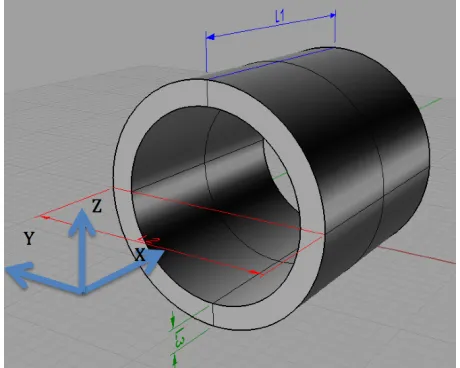
Finally, Tab. 2 provides details of the 9 DSMC test cases considered and Fig. 5 shows the geometry parameters.
Case
No. (m)L1 (m)L2 (m)L3 Angle of attack (o)
X007 1.0 1.0 0.1 0
X008 1.0 1.0 0.5 0
X009 1.0 1.0 0.25 0
X010 1.0 1.0 0.1 45
X011 1.0 1.0 0.5 45
X012 1.0 1.0 0.25 45
X013 1.0 1.0 0.1 90
X014 1.0 1.0 0.5 90
[image:3.595.310.540.324.508.2]X015 1.0 1.0 0.25 90
Table 2. Geometry and flow angles for the DSMC cases.
Figure 5. Geometry parameters for the DSMC and CFD test cases.
2.2 CFD Studies
Two CFD studies were undertaken using the rhoCentralFoam solver. The geometries were identical to the hollow cylinder DSMC test cases X009 (0o angle of attack) and X015 (90o angle of attack) described in Tab. 2. Mach 9, non-reacting flow of air as a perfect gas was considered using the discretisation schemes outlined in section 1.2, in conjunction with a Van Leer limiter [10]. This corresponded to free-stream flow conditions of velocity 2888.66 m/s, temperature 256.26 K, pressure 272.72 Pa, density 3.71!10-3 kg/m3 and a wall temperature of 700 K.
[image:3.595.58.282.350.516.2]100µm. This corresponded to a structured mesh of 347,304 cells for the 0o case and 1,486,508 cells for the 90o study. Both meshes were created using the open-source mesh generator Gmsh [11] and Fig. 6 shows details of the space discretisation. The 0o case was modelled using a 3D wedge, while the 90o case was modelled with ¼ symmetry. Finally, with rhoCentralFoam being a transient solver, time step sizes of 3.1!10-9 s (maximum Courant number 0.75) and 4.7!10-8 s (maximum Courant number 0.25) were employed for the 0o and 90o cases, respectively.
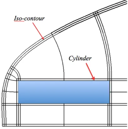
[image:4.595.70.276.319.527.2]In order to improve computational accuracy and stability, attempts were made to align our meshes as much as possible with the bow shock wave. To do this, a simulation was firstly performed using a non-aligned mesh. The bow shock location was then extracted as a Mach number 8.5 iso-contour. This iso-contour was then smoothed and offset around the body to generate near-shock mesh regions that would allow enhanced mesh control around the shock. These structured cell refinement regions are shown in Fig. 6.
Figure 6. Mach 8.5 iso-contour and structured mesh refinement regions around the 0o hollow cylinder.
In addition, the off-set furthest away from the body was set to be the new inlet for the next simulation. Once the mesh had been generated, the flow variables from the previous run were mapped onto the new mesh and a new simulation executed. This shock-alignment process was carried out twice.
3. RESULTS AND DISCUSSION 3.1 DSMC Cases
The overall aerothermodynamic loads acting on the cylinder are presented in Tab.3. The drag force for the 45o cases corresponds with the flow direction while the lift force is perpendicular to the flow.
Case No.
Drag force (N)
Lift force
(N)
Total heat load (W)
Angle of attack
(o)
X007 3.585 0.0 1.327!104 0
X008 5.662 0.0 1.674!104 0
X009 5.242 0.0 1.762!104 0
X010 6.924 0.279 2.386!104 45
X011 7.021 -0.734 2.296!104 45
X012 7.023 -0.399 2.374!104 45
X013 6.252 0.0 1.988!104 90
X014 6.278 0.0 1.999!104 90
X015 6.272 0.0 1.996!104 90
Table 3. Aerothermodynamic results for the DSMC cases (full cylinder).
The aerodynamic results in Tab.3 demonstrate that the maximum drag is seen to occur for the 45o flow cases, these having the maximum surface area exposure to the oncoming flow. For the 45o cases, the maximum drag occurs for the thickest of the hollow cylinders and the optimum heat flux among all cases is found for the 45o cylinder with the thinnest shell. As this case has the maximum internal and external surface area exposure it is anticipated that the heat transfer will be at an optimum.
For reasons of brevity, images are presented of the 45o flow cases only. Figs. 7-9 show the contours of heat flux, temperature and streamlines in the vicinity of the cylinder.
[image:4.595.313.539.536.717.2](b)
[image:5.595.274.533.79.512.2](c)
Figure 7. Surface heat flux contours for the 45o DSMC cases: (a) X010, (b) X011, (c) X012
(a)
(b)
[image:5.595.57.284.539.727.2](c)
Figure 8. Translational temperature contours for the 45o DSMC cases: (a) X010, (b) X011, (c) X012
[image:5.595.331.519.544.709.2]heat transfer occurs in the vicinity of the stagnation regions on the cylinders. The temperature profiles in Fig.8 highlight flow fields containing a distinctly diffuse bow shock accompanied by a compression region in the lee of the body. This is followed by a long, comet-like tail formation in the wake. Interestingly, from a fluid mechanics viewpoint, inside the cylinder with the thinnest shell (case X010), there appears to be a complex, three-dimensional vortex formation occurring, this originating from the lower lip of the cylinder, as shown in Fig. 9.
3.2 CFD Cases
The overall aerothermodynamic loads acting on the cylinder are presented in Tab.4.
Case Drag force
(N) force Lift (N)
Total heat load (W)
0o
1.567!104 0.0 4.077
!105
90o
1.826!104 0.0 3.575!105
Table 4. Aerothermodynamic results for the CFD cases (full cylinder).
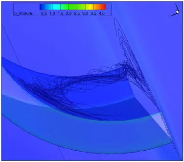
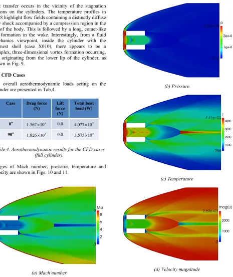
Images of Mach number, pressure, temperature and velocity are shown in Figs. 10 and 11.
(a) Mach number
(b) Pressure
(c) Temperature
[image:6.595.311.541.67.590.2](d) Velocity magnitude
[image:6.595.70.271.261.345.2](a) Mach number
(b) Pressure
(c) Temperature
[image:7.595.318.536.84.207.2](d) Velocity magnitude
Figure 11. CFD results for the 90o case.
The results for both the 0o and 90o cases demonstrate that a detached bow shock envelops the body. In comparison with the higher altitude, diffuse-shock DSMC results, the lower altitude CFD-predicted shocks are quite distinct and relatively thin. For the 0o case, the flow exterior to the cylinder contains a series of oblique shocks, expansion waves and recompression zones. A distinct bottle-shock is evident immediately downstream of the cylinder, terminating in a shock represented as a Mach disk.
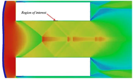
[image:7.595.317.535.482.613.2]Several interesting flow features are observed inside the 0o cylinder including a series of attached oblique shocks, recompression waves and Mach disks. There is evidence of shock wave – boundary layer interaction that produces a small recirculation bubble close to the cylinder wall. The effect of this phenomenon is to create a double oblique shock emanating from start and end of the recirculation zone as shown in Figs. 12 and 13.
[image:7.595.317.537.640.715.2]Figure 12. Shock-boundary layer interaction region.
These twin oblique shocks run to the cylinder centre-line where they form two shocks in the form of Mach disks. The resulting recompression waves are seen to reflect from cylinder surface to form two further, weaker Mach disks on the centre-line at the exit of the cylinder interior.
4 CONCLUSIONS
DSMC and CFD predictions of re-entry flows have been conducted using open-source codes. Several interesting flow features have been observed including diffuse, high altitude, rarefied shocks and, at lower altitudes in the continuum regime, shock-boundary layer interaction that produces double-shock structures. Our results demonstrate that it is now possible, using non-proprietary, open-source software to capture the complex physics involved in a complete re-entry trajectory from low-planetary orbit to ground level, including shock capture, high enthalpy, non-equilibrium effects and chemical reactions.
5 ACKNOWLEDGEMENTS
The authors would like to acknowledge the financial support provided by Conselho Nacional de Desenvolvimento Científico e Tecnológico under Grant No. 200473/2010-7. The dsmcFoam and rhoCentralFoam results were obtained using the EPSRC funded ARCHIE-WeSt High Performance Computer (www.archie-west.ac.uk) - EPSRC grant no. EP/K000586/1.
6 REFERENCES
1. Bird, G.A. (1994) Molecular gas dynamics and the direct simulation of gas flows, Clarendon, Oxford, 1994.
2. www.openfoam.com
3. Scanlon, T. J., Roohi, E., White, C., Darbandi, M. and Reese, J. M. (2010) An open source, parallel, DSMC code for rarefied gas flows in arbitrary geometries, Computers and Fluids, 39, 2078-2089.
4. Scanlon, T. J., White C., Borg, M. K., Palharini, R. C., Farbar, E. , Boyd I. D., Reese, J. M. and Brown, R. E. (2015) Open Source DSMC Chemistry Modelling for Hypersonic Flows, AIAA Journal (accepted).
5. Bird, G. A. (2011) The Q-K model for gas phase chemical reaction rates, Physics of Fluids, 23, 106101.
6. Greenshields, C.J., Weller, H. G., Gasparini, L. and Reese, J. M. (2009) Implementation of semi-discrete, non-staggered central schemes in a collocated, polyhedral, finite volume framework,
for high-speed viscous flows, International Journal For Numerical Methods In Fluids, 63, 1, 1-21.
7. Kurganov, A. and Tadmor, E. (2000) New High-Resolution Central Schemes for Nonlinear Conservation Laws and Convection-Diffusion Equations, Journal of Computational Physics, 160.1, 241-282.
8. Kurganov, A., Noelle, S., and Petrova, G. (2001) Semi-discrete central-upwind schemes for hypersonic conservation laws and Hamilton-Jacobi equations, SIAM J. Sci. Comput., 23, 3, 707-740.
9. Gutiérrez-Marcantoni, L.F., Tamagno, J. P. and Elaskar, S. A. (2012) High Speed Flow Simulation Using OpenFOAM, Asociación Argentina de Mecánica Computacional, 31, 2939-2959.
10. Van Leer, B. (1979). Towards the ultimate
conservative difference scheme V. A second order
sequel to Godunov's method, J. Comp. Phys. 32,
101–136.