City, University of London Institutional Repository
Citation
:
Lockett, R. D. and Greenhalgh, D. A. (2010). The optical characterisation of spray and soot formation in a diesel engine. Paper presented at the InternationalConference on Sustainable Combustion (SPEIC'10), 06 - 09 June 2010, Canary Islands.
This is the unspecified version of the paper.
This version of the publication may differ from the final published
version.
Permanent repository link:
http://openaccess.city.ac.uk/2071/Link to published version
:
Copyright and reuse:
City Research Online aims to make research
outputs of City, University of London available to a wider audience.
Copyright and Moral Rights remain with the author(s) and/or copyright
holders. URLs from City Research Online may be freely distributed and
linked to.
City Research Online: http://openaccess.city.ac.uk/ [email protected]
The optical characterisation of spray and soot formation in a diesel engine
1
R.D. Lockett*, 2D.A. Greenhalgh
1
School of Engineering & Mathematical Sciences, City University London, EC1V 0HB, UK
2
School of Engineering & Physical Sciences, Heriot-Watt University, Edinburgh, EH14 4AS, UK
*Corresponding author email: [email protected]
Abstract
Laser sheet drop-sizing (LSD) measurements of a Diesel spray and simultaneous laser induced incandescence/Mie scattering measurements of soot have been performed in an optically accessible, common rail, 1.9 litre, turbo-charged, direct injection Diesel engine. The diesel fuel injectors employed in this study were prototype five hole injectors, supplied by R. Bosch. An oxygenated surrogate Diesel fuel with an estimated cetane number of 54 was employed in order to reduce the amount of soot formed during combustion.
The prototype five-hole injector employed produced spray jets that were distinguishable in terms of the liquid volume fraction, drop-size distribution and spray penetration distance produced. The soot volume fraction formed during combustion was found to be correlated with drop-size distribution, and local soot particle size distribution was observed to be inversely correlated with local soot volume fraction
Keywords
Laser sheet dropsizing, laser induced fluorescence, Mie scattering, laser induced incandescence, laser diagnostics, diesel, spray, soot, engine, combustion fuel.
1. Introduction
Diesel soot formed during steady-state and transient engine operation remains an unresolved engineering problem. Multiple diesel injections, turbo-charging, exhaust gas recirculation, and diesel particulate filtration have been employed separately, and in combination, in order to reduce and manage exhaust-out particulate emissions [1].
A number of experimental diagnostics have been developed in order to investigate diesel fuel-air mixing, combustion, and emissions formation. Phase Doppler Anemometry (PDA), laser induced fluorescence (LIF), and laser sheet dropsizing (LSD) have been developed and employed to determine drop size distributions, liquid volume fraction and spray droplet velocity in diesel sprays [2]. LIF has been employed to characterise diesel combustion [2, 3]. Laser and light extinction, and variations of laser induced incandescence (LII) have been employed to characterise global and local soot properties during and after diesel combustion [2].
2. Experimental
2.1 The Engine
A turbo-charged 1.9 litre common rail direct injection diesel engine, modified in order to provide optical access into the cylindrical piston bowl, was employed in the study. The piston bowl geometry employed to facilitate optical access, resulted in an engine compression ratio of approximately 14.5. The engine was run at part load at 1200 rpm. The 800 bar common rail fuel injection system supplied an oxygenated surrogate fuel to the engine through prototype five-hole injectors in order to reduce the amount of soot formed during combustion.
2.2 The Surrogate Diesel
2.2.1 Laser Sheet Dropsizing in the Diesel Spray
A 70/30 mixture by volume of tetra-ethoxy-propane and tetraethylene glycol dimethyl ether was employed as a surrogate diesel fuel during the optical investigation of the diesel spray. This mixture had an estimated cetane number of 56. This surrogate fuel was selected for use in this experiment due to the relatively small amount of soot formed during combustion, facilitating the use of optical diagnostics for spray characterisation in the piston bowl for an extended period between cleaning cycles.
2.2.2 Laser Induced Incandescence (LII)/Mie Scattering from Diesel Soot
The second part of the experiment involved the use of simultaneous LII/Mie scattering from soot formed during combustion in the piston bowl. A small quantity of hepta-methyl nonane was added to tetra-ethoxy propane surrogate diesel in order to accurately control the amount of soot formed during combustion. This follows the use of tetra-ethoxy propane as a surrogate diesel fuel by Dec [5].
2.3 The Fuel Injection System
The fuel injection system was comprised of a Bosch high pressure pump and common rail, arranged to operate with a common rail pressure of 800 bar. The pump was modified, involving the replacement of conventional seals with viton seals. This was done in order to prevent pump failure, caused by absorption of oxygenated fuel into fuel seals.
The common rail supplied the surrogate diesel to prototype five-hole injector. The injector nozzles were located in the centre of the diesel piston bowls, approximately 0 mm to 5 mm below the top of the piston. The nozzles were angled downward, producing five spray jets, all with an angle of 15 deg below the horizontal.
2.4 Laser Sheet Dropsizing Measurements
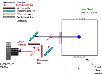
Right angle Mie scattering at 355nm, and the fluorescence obtained from the fluorescent seed in the diesel spray, passed through the base of the transparent piston bowl, onto a 45o angled mirror in an extended crankcase. The mirror reflected the light through a two-channel imaging system (LIF/Mie scattering) onto an ICCD camera, using a Nikon 50mm f1.2 lens, magnified with a Nikon 1.4x converter. The two channel optical imaging system for 355 nm laser sheet dropsizing is shown in Figure 1.
Figure 1: Layout of Two-Channel Imaging System Employed for Laser Sheet Drop-Sizing
The timing of the laser and ICCD camera were externally controlled using a multi-channel electronic timing system connected to the engine. The fuel injection was timed to begin at 5o before top dead centre (BTDC), and to last for a duration of 1.4 ms, to finish at 5o after top dead centre (ATDC). The simultaneous LIF/elastic scattering measurements were obtained from the diesel spray at top dead centre (TDC). 200 single shot images were obtained, together with a background, and a set of 10 laser profile images. The laser sheet dropsizing experiment described here has been presented and published elsewhere [2, 4].
2.5 Simultaneous LII/Mie Scattering Measurements
An Nd:YAG laser producing 532 nm radiation was formed into a 2-d sheet of width 30 mm, and thickness 0.2 mm. The 2-d laser sheet was directed through a fused silica window providing optical access to the transparent piston bowl, as described above. The energy of the laser pulses exiting the engine were measured during fuel injection, in order to determine the amount of laser energy absorbed during the fuel injection. The LII emission and elastic Mie scattering emitted from the soot in the piston bowl perpendicular to the laser sheet and towards the base of the piston bowl was imaged simultaneously onto an ICCD camera, using a two-channel optical imaging system similar to that shown in Figure 1.
Laser Sheet (Nd:YAG 355nm) Fused Silica Window Fluorescence signal Interference filter Mie signal 355nm bandpass Broadband mirror (Al)
335nm refle. mirror
PI ICCD 600x400 CAMERA
Fluorescence Filter
DUAL Imaging Setup
Fused silica windowThe LII signal was filtered using a broadband band-pass optical filter, in order to eliminate contamination of the LII signal by optical emission from the burning gases and soot formed in the piston bowl. The fuel injection was timed to begin at 5o BTDC, and to last for a duration of 1.4 ms, to finish at 5o ATDC. Simultaneous LII/Mie scattering measurements were obtained from combustion soot at crankshaft angles 12o ATDC to 19o ATDC.
3. Processing of Image Data
The two-channel imaging system (Figure 1) employed in the laser sheet dropsizing measurements and the simultaneous LII/Mie scattering measurements from in-cylinder soot produced elastic scattering images and inelastic scattering images that were optically mismatched relative to each other. This was a consequence of directing the two signals along different optical paths towards the camera. The different optical paths produced various optical distortions that required correction.
Processed single shot images were obtained by (1) subtracting mean backgrounds, followed by (2) dividing by a laser calibration image. Mean processed images were then obtained from the processed single shot images. In order to provide pixel-to-pixel matching of the elastic versus inelastic scattering mean images, one mean image was chosen to be the master image, while the other mean image was chosen to be the slave image. Both mean images were converted to binary images using a 5 % intensity threshold. The slave mean image was then modified and compared with the master mean image using an eight degree of freedom optimization. The eight degrees of freedom matched up (1) the co-ordinates of the origin (2), (2) the horizontal and vertical axis scales (2), (3) the horizontal and vertical axis relative angles (2), and (4) the horizontal and vertical axis image distortion through image shear (2).
The eight factors derived from the eight degree of freedom optimization were then employed to obtain a set of optically matched single shot images from the set of processed slave images.
4. Results
Figure 2 below shows false colour images of (a) mean relative liquid volume fraction (LIF) and (b) mean elastic Mie scattering, obtained from the diesel spray at TDC.
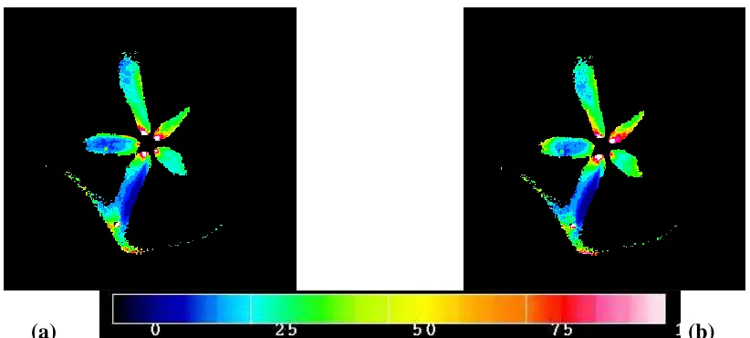
Figure 3 below shows the relative drop size distribution (Sauter mean diameter d32), derived
from the laser sheet dropsizing measurements obtained from the diesel spray at TDC, from two sets of 100 processed images.
Figure 4 below shows (a) false colour images of instantaneous relative soot volume fraction (LII) and (b) elastic Mie scattering obtained from in-cylinder diesel soot at 12o ATDC.
Figure 5 below shows (a) instantaneous soot particle number density, and (b) soot particle size distribution (d63) determined at 12o ATDC.
(a) (b)
Figure 2: (a) Mean relative liquid volume fraction in diesel spray (LIF), and (b) Mean elastic Mie scattering image, obtained at TDC.
[image:6.595.105.512.84.269.2](a) (b)
Figure 3: Relative drop size distribution (Sauter mean diameter d32) obtained in the diesel
[image:6.595.101.512.445.630.2](a) (b)
Figure 4: (a) Instantaneous relative soot volume fraction (LII) and (b) elastic Mie scattering, obtained from in-cylinder diesel soot at 12o ATDC.
(a) (b)
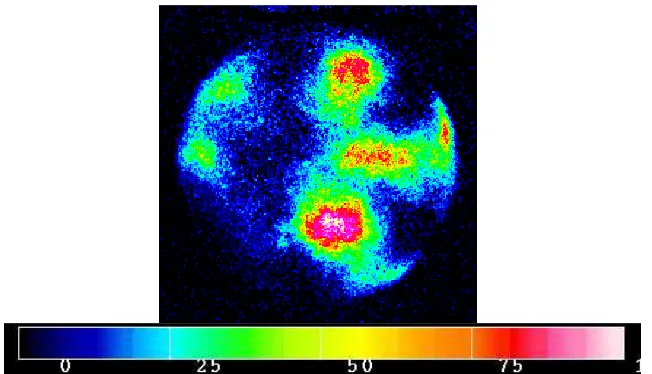
[image:7.595.105.507.84.271.2] [image:7.595.102.510.449.638.2]Figure 6: Mean relative soot volume fraction formed in the piston bowl at 12o ATDC
5. Discussion
Figure 2 (a) reveals that the individual fuel jets emitted from the injector exhibit different behavior. Defining the azimuthal angle anti-clockwise relative to the horizontal axis, the jets located at π/6 and 11π/6 evaporate before reaching the wall of the piston bowl. The jets located at 3π/5, π, and 7π/5 appear to exhibit deeper penetration.
Figure 3 (a) and (b) show that the fuel jets exhibit different drop-size distributions. The fuel jets located at π/6, 3π/5 and 11π/6 have similar drop-size distributions, except for the region near the tip of the 3π/5 spray jet. The fuel jets located at π and 7π/5 contain smaller droplets relative to the other three fuel jets.
Considering Figure 4 (a) together with Figures 5 (a) and (b), it can be observed that in regions with large local soot volume fraction, the soot present appears to be comprised of a large quantity of small soot particles, while regions with low soot volume fraction, the soot appears to be comprised of a small number of large soot particles, or of course, no soot particles at all.
Figure 6 shows the mean soot volume fraction in the plane of the laser sheet, obtained at 12o ATDC. The regions where soot appears seem to be unconnected with the position of the spray jets, observable in Figures 2 (a) and (b). It should be remembered however, that the air flow in the piston bowl is subject to swirl. Soot formed during combustion at approximately TDC to 5o ATDC is transported in a clockwise direction by the swirling flow at an approximate rate of 4o per crankshaft degree (~ 30o /ms). When time is reversed by 1.7 ms (12o CA), the location of the soot regions observable in Figure 6 coincide with the location of the fuel jets observable in Figures 2 (a) and (b).
6. Conclusions
1. The prototype injector produced fuel jets with varying internal liquid volume fraction, drop size distribution, and fuel jet penetration into the surrounding air flow.
2. Local soot particle size distribution correlates inversely with local soot volume fraction. This suggests that in regions with relatively large local soot volume fraction, the soot present is comprised of a large number of small soot particles. Conversely, in regions where the local soot volume fraction is small, but non-zero, the soot present appears to be comprised of a small number of large soot particles.
3. Local soot volume fraction formed during combustion correlates with mean droplet size in the spray. This suggests that spray jets containing relatively smaller droplets evaporate and mix more effectively than spray jets containing larger droplets, hence producing less combustion soot.
Acknowledgements
This work was funded through the EU-ZODIAC programme.
References
1. T.V. Johnson, SAE 2006-01-0030, SAE Technical Paper Series (2006).
2. Applied Combustion Diagnostics, eds. K. Kohse-Hoinghaus and J.B. Jeffries, Taylor and Francis 2002, ISBN 1-56032-938-6.
3. T. Lachaux and M.P.B. Musculus, Proc. Comb. Inst. 31 (2007) 2921 – 2929.
4. R.D. Lockett, J. Richter, D.A. Greenhalgh, CWC2, Proc. CLEO/Europe IEEE Cat. No. 98TH8326 (1998).