UNIVERSITI TEKNIKAL MALAYSIA MELAKA
EFFECT OF ACETONE VAPOR ON MECHANICAL
PROPERTIES OF FUSED DEPOSITION MODELING
PRINTED PART
This report is submitted in accordance with the requirement of the Universiti Teknikal Malaysia Melaka (UTeM) for the Bachelor of Manufacturing Engineering
Technology (Product Design) with Honours.
by
NURUL SHAHIRA FARHANA BINTI FADZLI B071410410
950401-06-6078
UNIVERSITI TEKNIKAL MALAYSIA MELAKA
BORANG PENGESAHAN STATUS LAPORAN PROJEK SARJANA MUDA
TAJUK: Effect of Acetone Vapor on Mechanical Properties of Fused Deposition Modeling Printed Part
SESI PENGAJIAN: 2017/18 Semester 1
Saya NURUL SHAHIRA FARHANA BINTI FADZLI
mengaku membenarkan Laporan PSM ini disimpan di Perpustakaan Universiti Teknikal Malaysia Melaka (UTeM) dengan syarat-syarat kegunaan seperti berikut:
1. Laporan PSM adalah hak milik Universiti Teknikal Malaysia Melaka dan penulis. 2. Perpustakaan Universiti Teknikal Malaysia Melaka dibenarkan membuat salinan
untuk tujuan pengajian sahaja dengan izin penulis.
3. Perpustakaan dibenarkan membuat salinan laporan PSM ini sebagai bahan pertukaran antara institusi pengajian tinggi.
4. **Sila tandakan ( )
SULIT
TERHAD
TIDAK TERHAD
(Mengandungi maklumat yang berdarjah keselamatan atau kepentingan Malaysia sebagaimana yang termaktub dalam AKTA RAHSIA RASMI 1972)
(Mengandungi maklumat TERHAD yang telah ditentukan oleh organisasi/badan di mana penyelidikan dijalankan)
Alamat Tetap:
NO. 18 Jalan Kerdau Impian 2, Taman Kerdau Impian,
Temerloh, Pahang.
Tarikh: ________________________
Disahkan oleh:
Cop Rasmi:
DECLARATION
I hereby, declared this report entitled “EFFECT OF ACETONE VAPOR ON MECHANICAL PROPERTIES OF FUSED DEPOSITION MODELING PRINTED PART” is the results of my own research except as cited in references.
Signature :
Author’s Name : NURUL SHAHIRA FARHANA BT FADZLI
APPROVAL
This report is submitted to the Faculty of Engineering Technology of UTeM as a partial fulfillment of the requirements for the degree of Bachelor of Manufacturing Engineering Technology (Product Design) with Honours. The member of the supervisory is as follow:
………
MADAM NURUL AIN BINTI MAIDIN
i
ABSTRAK
ii
ABSTRACT
This project entitled Effect of Acetone Vapor on Mechanical Properties of Fused Deposition Modeling Printed Part is focus on the Rapid Prototyping (RP) technologies with Fused Depostion Modeling (FDM) technique. RP has the benefit being capable to create very complex geometries, which could be impossible with traditional methods or fabricated at high cost. For material cost properties, the cost of RP parts is mostly related to the size of the product. The project will be used polymer-based material specifically Acrylonitrile Butadiene Styrene (ABS). However, the FDM technique suffers from poor surface roughness, restricting it application on some areas requiring high surface integrity. Therefore, a post processing stage is required to improve the surface roughness of the FDM printed part. In this study, an acetone vapor post process will be employed to improve the surface roughness of the part but the scope of the study will focus on the effect of mechanical properties of the printed part. Mechanical anisotropy behaviour of the specimen will be investigated via tensile test, flexure test and microstructural arrangement. As conclusion, the results of implementation of acetone vapor as post processing of FDM printed part will be compared to the original printed part regarding the mechanical properties.
iii
DEDICATION
iv
ACKNOWLEDGEMENT
It has been an adventure journey for me while completing this final year project report. However, with the helps from beneficent people, I am successfully completed this report. I am so grateful that now I can express my gratitude to all of them.
I am thankful and would like to express my sincere gratitude to my supervisor Madam Nurul Ain binti Maidin for her precious guidance, continuous encouragement and constant support in making this research possible. I really appreciate her guidance from the beginning to the end that enabled me to develop an understanding of this report project thoroughly. Without her advice and assistance it would be harder for me to complete this report. Sincerely thanks too for the time spent proofreading and correcting my mistakes.
My truthful appreciation goes to all lecturers and members of the Manufacturing Engineering Technology Department, UTeM, who helped me in any ways and made my education journey in UTeM pleasant and unforgettable. Many thanks go to BETD group members for their excellent co-operation, inspirations and supports during this study.
v
TABLE OF CONTENT
Abstrak i
Abstract ii
Dedication iii
Acknowledgement iv
Table of Content v
List of Tables vii
List of Figures viii
List Abbreviations, Symbols and Nomenclatures x
CHAPTER 1: INTRODUCTION 1
1.1 Research Background 1
1.2 Problem Statement 2
1.3 Objectives 3
1.4 Scopes 3
CHAPTER 2: LITERATURE REVIEW 6
2.1 Rapid Prototyping 6
2.1.1 Solid Freeform Fabrication 8
2.1.2 Fused Deposition Modeling (FDM) 9
2.1.3 Material 11
2.1.4 STL File Format 14
2.1.5 Fused Deposition Modeling Rapid Prototyping
Machine (UP Plus 2) 15
2.2 Mechanical Properties 17
2.2.1 General Definition of Mechanical properties 19
2.2.2 Mechanical Properties of ABS 20
2.2.3 Mechanical Properties of Investigation 20
2.3 Acetone 23
vi
CHAPTER 3: METHODOLOGY 27
3.1 Project Planning 27
3.2 Experimental Design 29
3.2.1 Specimen Preparation 29
3.2.2 Tensile Test 32
3.2.3 Flexure test 35
3.2.4 Microstructural Arrangement 37
CHAPTER 4: RESULT AND DISCUSSION 38
4.1 Tensile Test 38
4.2 Flexure test 43
4.3 Microstructural Arrangement 47
4.4 Final Result 49
CHAPTER 5: CONCLUSION AND RECOMMENDATION 51
6.1 Conclusion 51
6.2 Recommendation 52
REFERENCES 53
vii
LIST OF TABLES
2.1 2.2 2.3 2.4
Comparison of solid freeform fabrication method
Comparison of thermal properties for ABS and PLA filaments Specification of UP Plus 2 FDM RP 3D printer
General definition for type of mechanical properties
9 12 16 19
2.5 Mechanical Properties of ABS 20
4.1 Data collection of tensile test 39
viii
LIST OF FIGURES
2.1 Schematic diagram of FDM machine 10
2.2 2.3 2.4 2.5 2.6 2.7
Fused deposition modeling: 1 - nozzle ejecting molten plastic, 2 - deposited material (modelled part), 3 - controlled movable table
Example of ASCII STL file
Fused Deposition Modeling RP Machine (UP Plus 2) Beam of material under bending. Extreme fibers at B (compression) and A (tension)
Full structural formula of acetone with dimensions Skeletal formula of acetone
11 14 15 22 23 24
3.1 Flowchart of the development of the study 28
3.2 Parameter setup for printing part 29
3.3 Printing process for specimens’ part 30
3.4 Complete printed specimens’ part 30
3.5 Paper towels line inside the metal can and secured with magnets
31
3.6 Specimen hanged inside the metal can with a thread and magnet that stacked to the metal lid
31
3.7 Marking process for flexure test 32
3.8 Marking process for tensile test 32
3.9 Tensile test 33
3.10 Mechanism of tensile test 33
3.11 Dimensional geometry for tensile test 34
3.12 Flexure test 35
3.13 Mechanism of flexure test 36
3.14 Dimensional geometry for flexure test 36
3.15 Microstructural arrangement check 37
4.1 Graph of maximum load versus specimens for tensile test 40
ix 4.3 Graph of average tensile strength versus type of part 42 4.4 Graph of maximum load versus specimens for flexure test 44
4.5 Graph of flexural strength versus specimens 45
4.6 Graph of average flexural strength versus type of part 46
4.7 Microstructure arrangement of original part 47
x
LIST OF ABBREVIATIONS, SYMBOLS AND
NOMENCLATURE
ABS - Acrylonitrile Butadiene Styrene AM - Additive Manufacturing
ASCII - American Standard Code for Information Interchange ASTM - American Society for Testing and Materials
CAD - Computer Aided Drawing CAM - Computer Aided Manufacturing CNC - Computer Numerical Control
CT - Computerized Tomography
FDM - Fused Deposition Modeling MIG - Metal Inert Gas
NEMA - National Electrical Manufacturer Association PLA - Polylactic Acid
RP - Rapid Prototyping
SFF - Solid Freeform Fabrication STL - STereoLithography
3D - Three-dimensional
σt - Tensile strength
1 This chapter mostly presents the background of the project. Besides that, this chapter would be included with problem statement, objectives, and scopes of the project. The background describes about the overview of the project. Meanwhile the problem statement states the reason of conducting this project. The aim of the project describes by the objectives and the scopes would be the limitations of the project implementation.
1.1 Research Background
Mechanical properties of materials are important to be considered in order to make the parts that produced has a good quality. Thus, mechanical properties are also used to help classify and identify material. The properties can be defined as the ability of the material to undergo any stress of deflection which will affect the parts physically or mechanically. Mechanical properties can be classified to many types such as tensile strength, flexural strength, shear strength, toughness, hardness and elasticity. The mechanical properties that will be studied for this projects are tensile strength, flexural strength and microstructural arrangement of the material.
Rapid prototyping (RP) consists a set of techniques that used to manufacture a measure model of a physical part or assembly by using three dimensional computer aided design (CAD) data in a short time. The creation of the part or assembly is commonly completed the use of three-dimensional printing or ‘additive manufacturing’ technology. One of the commonly used techniques of rapid prototyping is Fused Deposition Modeling (FDM) which works by a heated nozzle
INTRODUCTION
2 laying down molten material in layers to produce a desired part. The nozzle is heated to melt down the material and can be relocated in both parallel and perpendicular directions by a numerically controlled mechanism which will directly structure by a computer-aided manufacturing (CAM) software package. Therefore, the type of machine that will be used to produce the specimens for this project is FDM RP machine. There are a few materials that can be used for this FDM technique. For examples, Acrylonitrile Butadiene Styrene (ABS), Polycarbonate (PC), Polyamide (PA), Polystyrene (PS), Polylactic acid (PLA), lignin and rubber. The materials can be used with different trade-offs between strength and temperature properties. Thus, the selected material that will be used for this project is ABS which is a thermoplastic that is malleable when heated. Besides that, ABS allow the post-processing process to be easier which suitable for this project that will undergo a post-processing for the printed part. The material exists in plastic filament or metal wire form that is compatible with FDM machine.
Acetone is a colorless, volatile and flammable liquid used as a solvent and antiseptic. It is can be dissolved with water and serves as an important solvent which is typically for cleaning purposes in the laboratory. Acetone is the best solvent for many plastics and some synthetic fibres. Therefore, an acetone will be used in the phase of post-processing for this project printed part. An acetone vapor will be applied to the complete printed part. The acetone vapor will be produced by a simple and safe method. The vaporing process of printed part will be applied with in a set duration of time. The results will show the effect of acetone vapor on the mechanical properties of the FDM printed part.
1.2 Problem Statement
3 roughness of the printed part. The printed part that suffers from poor roughness restricting its application in some areas requiring high surface integrity. Therefore it is required a post-processing stage for the printed part in order to improve the surface finish, thus will affect the mechanical properties of the part. The mechanical properties for finished printed part are important in order ensure the part produced with a good quality and can undergo any stress or deflection at a certain range of conditions. There are many post-processing solutions can be applied for improving the mechanical properties of the printed part. Therefore, it can be differentiate the mechanical properties of the original part with the part that undergo post-processing process.
1.3 Objectives
To improve the mechanical properties of a printed FDM part, it is necessary to perform the work study needed precisely and accurately so that an improvement of mechanical properties for a FDM printed part can be obtained. The purposes of this research writing is:
a) To study the effect of acetone vapor on mechanical properties of Fused Deposition Modelling (FDM) printed part.
b) To conduct a test in order to differentiate the mechanical properties of the original printed part with the acetone vapor part.
c) To optimise the mechanical properties of ABS fused deposition modeling printed part for tensile test and flexure test.
1.4 Scopes
4 that can be used to create robust plastic objects for everyday use. Besides that, ABS filament is better malleable with easier post-processing. Therefore it is suitable for the project as the part will undergo post-processing process. Besides that, the printed part can be cut, filed, sanded, painted and bonded. Even though the material is not biodegradable but it can be easily recycled.
The project will also cover the mechanical properties of the FDM printed part. Mechanical properties are important to ensure the part produced in a good quality. Therefore the mechanical properties will focus on the tensile strength, flexural strength (bending) and microstructural arrangement of the material. In order to improve the surface roughness, the printed part will undergo post-processing process which is acetone vaporing process. The acetone vapor will be produced by a simple and safe method from an acetone solution. Then, the printed specimen part will be vapored with the acetone vapor in a range of time.
Therefore, the design of the specimen for tensile strength test will be a dog bone shape. The specimen is a regular sample cross-section. It consist of two shoulders and a gage section in between. The shoulders are big so they can be freely gripped, whereas the gauge section has a smaller cross-section so that the deformation and failure can occur in that area. Meanwhile, the design of specimen for flexure test will be a simple rectangular block. The specimens can be divided to five types of part which were the original without undergo the vaporing process and the part that undergo vaporing process of four different set duration of time. The set duration of time were 15 minutes, 30 minutes, 45 minutes and 1 hour. Each type of part will be prepared by two samples. The designs will be done by using Solidwork software as the computer-aided design. Then, the design was converted to STL file before proceed with fabricating the specimens by 3D printing process of FDM technique for rapid prototyping machine modeled Up Plus.
6 While the first chapter of the project describes background, problem statement, objectives as well as the scopes of the project, this chapter proceeds with referenced review from the relevant literature. Generally, this chapter contains a literature review on rapid prototyping of fused deposition modelling technique which includes the materials used. Sources of information were obtained from secondary sources which are books, journals, reports and electronic-media publications. The primary objective of this review is aiming at searching the current status and history of mechanical properties for a FDM printed part. Hence, this chapter will narrow the topic into the element that commonly used for improving the mechanical properties of the FDM printed part. It also explains elements related to the testing for the mechanical properties. After explaining the studies, this chapter enlightened the tools that will be used for this project.
2.1 Rapid Prototyping
The term Rapid Prototyping or Additive Manufacturing (AM) is used in a variety of industries to describe a process which rapidly creates the representation of a system or part prior to final release or commercialization. Additive manufacturing is a layer-based automated fabrication process for making scaled three-dimensional physical objects directly from 3D-CAD data, without using part-dependent tools. It was originally called 3D printing, and this term is still frequently used, however other
LITERATURE REVIEW
7 terms used in this technology include additive layer manufacturing, rapid prototyping, and direct manufacturing (Gibson et al., 2010). Nowadays, rapid prototyping are being used for a wide range of applications and also used to manufacture production quality parts in rather small numbers if needed. The technology being used by some modern sculptors in the process to produce complex shapes for fine art exhibitions.
Briefly, rapid prototyping takes virtual design from CAD or animation modeling software that converts them into cross sections but still virtual, and then form each cross section in physical space, one after the next until the model is finished.
In the area of prototyping fabrication, the machine reads in data from a CAD drawing and the lays down successive layers of liquid or powdered material, then builds up the model from a long series of cross sections. These layers which correspond to the digital move segment from the CAD model are glued together or fused commonly the use of a laser automatically to create the final shape. The primary advantage to additive manufacturing is the ability to create almost any kind of geometry excluding trapped negative volumes. The standard interface between CAD software and rapid prototyping machines is the STL file format (Wikipedia, 2017).
As stated in (Wikipedia, 2017) the word ‘rapid’ is relative to construct a model with contemporary machines typically takes three to seventy two hours, depending on the machine type and model size. The usage in micro rapid technologies is correct, the products made are ready very fast and the machines can build the parts in parallel.
Advances in technology allow the machines to use multiple materials in the manufacturing of the parts. It is important as it can use one material with a high melting point for the completed part while another material with low melting point as filter to separate individually moving parts within the model. As the model is finished, it will be heated to the point where the undesired material melts away. Even though the traditional injection molding is required a low cost in plastic manufacturing, rapid prototyping can be used to produce finished good in a single phase soon.
8 machine. The techniques could consider to reduce the cost of prototyping machine in the future.
2.1.1 Solid Freeform Fabrication
Solid freeform fabrication is a collective term for production techniques for the manufacture of a physical object by sequentially delivering energy and material to a specific point in space. SFF is also referred as rapid prototyping, rapid manufacturing, layered manufacturing or additive fabrication. The usage of soli freeform fabrication is less time consuming because SFF techniques require less post-processing for the same complex shapes and do not use product-specific tools, such as a mold , which must first be made before can be produced. Besides that, the machine does not have to be changed over for each product series and does not require fixation of the product, which also gives it time savings.
Techniques of solid freeform fabrication (Wikipedia, 2017): a) Fused deposition modeling
Fused deposition modeling extrudes hot plastic through a nozzle, layer by layer builds up a model.
b) Laser engineered ne shaping
A laser is used to melt metal powder and deposition it on the part directly. The advantage that the part is fully solid and the metal alloy composition can be dynamically changed over the volume of the part.
c) Laminated object manufacturing
Sheets of paper or plastic film are attached to previous layers by either sprayed glue, heating or embedded adhesive and then the desired outline of the layer is cut by laser or knife. The finished part typically looks and acts like a wood.
d) Selective laser sintering (SLS)
9 Stereolithography is using a laser to liquid substances polymerize
f) Shape deposition manufacturing
Alternatingly deposing sacrificial or part material by a printhead and machining it in shape.
g) 3D printing
Layers of a fine powder are attached by printing a water-based adhesive from an inkjet printhead that includes thermal phase change inkjet and photopolymer phase change inkjet.
h) Solid ground curing
Same as stereolithography, uses solid wax for support.
Table 2.1: Comparison of solid freeform fabrication method (Source: <https://en.wikipedia.org/wiki/Solid_freeform_fabrication> 15/03/2017)
2.1.2 Fused Deposition Modeling (FDM)
After 20 years of research, additive manufacturing (AM) continues to grow with the addition of new technologies, methods and applications (Lee et al., 2004). Fused deposition modeling which is normally referred by its initials FDM, is a type of additive manufacturing techniques for rapid prototyping technology that commonly used in engineering design. The technology was
Techniques Accuracy
(mm/mm) Maximum part size (mm) Process time (hh:mm) Fused deposition
modeling 0.005 254 x 254 x 254 (Stratasys) 12:39 Laminated object
manufacturing 0.01 (Cubic Technologies) 812 x 558 x 508 11:02 Selective laser
sintering 0.005 381 x 330 x 457 (3D Systems) 4:55 Solid ground
curing 0.006 508 x 355 x 508 (Cubital) 11:21 Stereolithography 0.003 990 x 787 x 508
10 evolved through S. Scott Crump within the late 1980s and commercialized in 1990. The FDM system has been commercially developed by Stratasys Inc. USA (Garg and Singh, 2013).
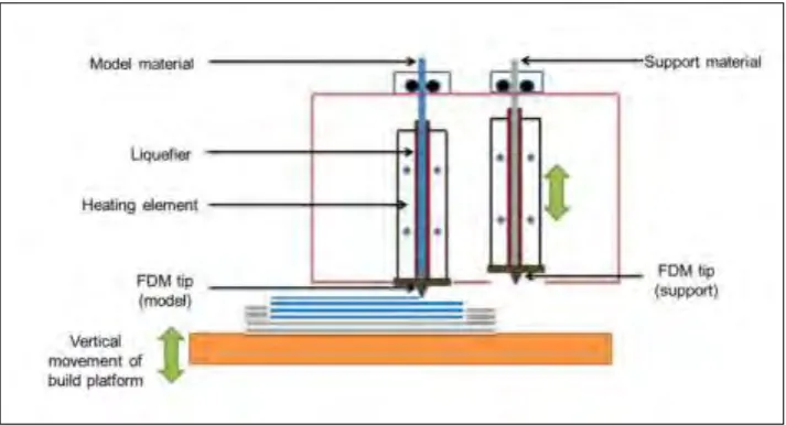
[image:24.595.159.516.479.672.2]According to Lee et al. (2007), the operating principle of FDM techniques is possibly most different additive manufacturing techniques including 3D printing and stereolithigraphy which is by using laying down material in layers. In this process, FDM materials like ABS, elastomers, polycarbonates, polyphenol sulphones and investment casting wax feeds into the temperature-controlled FDM extrusion head, where it is heated to a semi-liquid state. A plastic filament or metal cord is unwound from a coil and supplies material to the extrusion nozzle that can turn the flow on and off(Lee et al., 2007). The nozzle is heated to melt the material and can be moved in each horizontal and vertical axes through a numerically managed mechanisms, directly managed with the aid of a computer-aided manufacturing (CAM) software package. The head extrudes and deposits the material in thin layers onto a fixtureless base. The head directs the material into place with precision, as each layer is extruded it bonds to the previous layer and solidifies. The designed object emerges as a solid three-dimensional part without the need for tooling.