Thesis by
James Nelson Shoolery
In Partial Fulfillment of the Requirements For the Degree of
Doctor of Philosophy
California Institute of Technology Pasadena, California
It is a great pleasure to acknowledge the constant friendly advice and helpful discussions of Professor Don M. Yost,. with whom my association has been a never failing source of inspirati.on. I am also grateful to Professor William D. Gwinn of the University of California for introducing me to the field of microwave spectroscopy and for his continued encourage-ment throughout the course of this work.
For the enthusiastic cooperation of Dr. Robert G. Shulman in the task of recording and interpreting the spectral data I wish to express my sincere appreciation. Tb..anks are also due Professors W. H. Pickering and H. V. Neher and Mr. Bart Locanthi, who contributed to the success of this venture through valuable counsel concerning electronic problems.
I am deeply grateful to the Research Corporation, without whose
The theory of microwave spectroscopy is first presented in some de-tailo Following this, sources of errors in structure determinations based on moment of inertia data are considered, and approximate equations for estimating their effects are derived.
A microwave spectroscope has been assembled and its design, construe-tion, and operation are discussed. Microwave spectra in the region from 20 to 25 kmc have been obtained for HN14cJ.2ol.6, HN15cl2oJ.6, and DN14cl2
ol6o
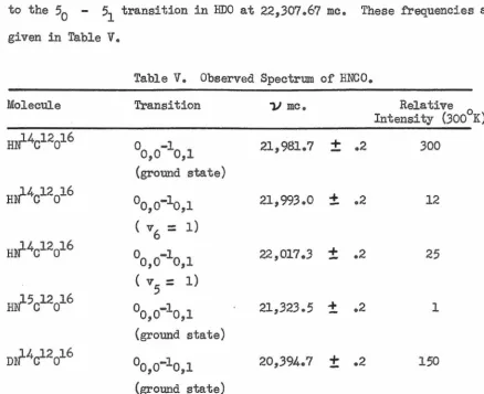
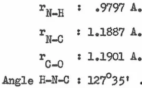
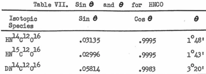
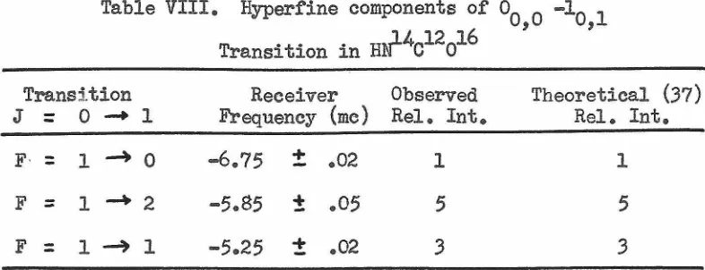
A rotational constant obtained from an infrared study of HNCO by L. H. Jones is combined with the microwave data to yield the interatomic dis• . tances and bond angle. High resolution studies of the spectra of HNCO and HNCS permit evaluation of their electric quadrupole coupling constants and qualitative deductions concerning their structures to be made. The molecular species cF3-c:c-H, CF3-cl3!C-H, cF3-c:cl3_H, and cF3-c;c-D have been observed to absorb in the microwave region, and from the frequencies of these absorptions the C!C and C-H distances are determined. In ad.di-tion, the measured moments of inertia are employed to calculate consist-ent sets of the remaining three parameters in CF
3
-c:c-H.
The application of the electron diffraction data ofw.
F. Sheehan, Jr., to this problem to determine which set of parameters actually represents the structure is described. Stark effect measurements are presented which determine the dipole moments of HN14cl2ol6 in three vibrational states and of DNCO, OCS, HPART
I.
II.
III.
IV.
v.
VI.
VII.
VIII.
APPENDJX I.
PROPOSITIONS.
TITLE
General Theory of Pure Rotational Spectra.
Discussion of Errors in Microwave Structure Determinations.
Design, Construction, and Operation of the Microwave Spectroscope.
The Determination of the Structure of Isocyanic Acid in the Vapor Phase.
The Structure of CF3-C5C-H from Microwave and Electron Diffraction Data.
Electric Dipole Moments from Stark Effect Measurements.
Other Substances Which Were Studied.
References
PAGE
1
27
31
46
68
77
92
94
97
I. GENERAL THIDRY OF PURE ROTATIONAL SPECTRA.
Pure rotational spectra for only a few very light molecules had been
observed prior to World War II. The development of microwave radar during
the war had a profound effect on the field of spectroscopy, because it
opened up a new region of the spectrum which had been reached previously
only by the pioneering work of Cleeton and Williams (1), who used
semi-optical methods to detect a broad absorption band in ammonia at 1.25 cm.-1
Insofar as the term is applied to pure rotational spectra, microwave
spectroscopy has come to mean the detection and measurement of a sharp
line absorption spectrum due to molecular transitions from one allowed
state to another, during which only the mode of rotation changes.
Detec-tion is accomplished by passing microwave energy through the substance
contained in a rectangular cell and measuring the attenuation as a
func-tion of frequency. A monochromatic, single phase source of energy allows
the use of a tuned detector and results in a resolving power 100,000 times
better than that of the best infrared grating instrument. Frequency
measurements can be made electronically to one pa.rt in 107.
During its brief but eventful existence, the field of microwave spectroscopy has become a beehive of activity. No less than thirty
spec-troscopes were in operation at the last count, and untold numbers were
under construction. Spectra have been obtained for several score of
com-pounds, and from most of these it has been possible to obtain useful
structural information. A description of early work in the field is
con-tained in two excellent reviews (2,3) of the subject. The remainder of
this section will be concerned with the systematic treatment of the pure
1. THE RIGID ROTOR.
Let us consider a rigid, rotating molecule consisting of two atoms
a fixed distance, r , apart. For a system with no external forces, for example, a molecule suspended in free space, the axis of rotation passes
through the center of mass. The kinetic energy of the molecule is given
by
T =
t
lc.l- :.
P2
/21 , (1-1)where w is the angular velocity of the molecule with respect to a
prin-cipal axis through the center of mass, I is the moment of inertia about
this axis, and P is the angular momentum about the same axis. Since the
potential energy of such a rigid rotor may be set equal to zero, the wave
equation for the system is
{ P2
/2I }\.JI (
8 >~)
=
·E\f' (
6 >~)
(1-2)in which "/'(8~</>) is a probability amplitude function for finding the line joining the atoms oriented at angles
8
and(>
with respect to space fixed axes. The square of the total angular momentum 11).8.y be written in operatorform as
Therefore,
- 1i2
21P2 :: -11.2 {
1O
(sin 8_l_ )
+
1d
2 ) (1-3)op sin 8 (}8 dB sin2g
JP •
{
1
J
sin 8 ()9
(sin 8
d
't
)
+
1a
2'i' } =
J
8 sin2 9a
</> 2E
'f' •
(1-4)Equation (1-4) can be solved by separation of the variables and subsequent
application of the polynomial method, The final result is that the series
namely
E
=
ii
2 J( J+l )/2I. J :: 0,1,2, •••••The quantity h/811" 2cr is conventionally called B, and
E/hc (cm-1)
=
BJ( J+l) • The complete, normalized, rotational wave function is(1-5)
(1-6)
'f' (
8,~)
:f-2._)Ji
{(2J +1) (J+
IMJ!) ]t
PM (cos 6)e
iM¢>, (1-7)l
21T 2(J+IMI)! JM
where the PJ (cos 8) are the associated Legendre f'unctions,and J and M
are quantum numbers.
Eigenvalues of
:r2
and Pz are easily obtained. The square of thetotal angular momentum,
P2,
is given byp2
=
J ( J + 1 )-ii
2 • (1-8)The component of angular momentum along the space fixed Z axis is
2. THE SYMMETRIC TOP.!..
p
=
Mh •z
A symmetric top molecule is one in which two of the principal
(1-9)
moments of inertia are equal. The kinetic energy of rotation of a
sym-metric top is given by
T P 2/;2I
+
P 2/;21+
P 2/;21x xx y yy z zz ' (2-1)
where x, y, z are the directions of the principal axes. Let us designate
the x direction as the one for which the moment of inertia is unique. The
projection of angular momentum along the x axis is quantized and is
K
=
0,1,2, •••• • .(2-2)p2
+
P2
+
p2=
J(J+
1)11
2 •x y z (2-3)
If I :. I
zz' then
yy
T :: K2112/2I
+
{ J(J+
1)-
K2}..fi
2 /2I •:xx zz
(2-4)
The three principal axes in molecules are labeled the a, b, c axes in
order of increasing moment of inertia. The quantities A ~ B Q C are
de-fined as
A
=
h 1811' 2 cl • B=
h/8 11 2 c\b ; C :: h/8 1'1 2 cI •cc
1' aa '
If x corresponds to a, then C equals B, the rotor is prolate, and
E/hc
=
BJ(J+
1)+
(A-B)K2 •If x corresponds to c, then A equals B, the rotor is oblate, and
E/hc ::: BJ(J
+
1)+
(C-B)K2•(2-5)
(2-6)
By writing the Hamiltonian for the symmetric top in terms of a set
of Eulerian angles defining the orientation of principal axes in the body
with respect to axes fixed in space, we can solve the wave equation, H "I-'
:=. E
'¥
,
for the symmetric top eigenfunctions. Such a calculationyields the following expression for
'+' :
o/
JKM :: NJKM F(x) x}fK-MI (l-x)ifK+
Ml
exp(iM y, + iK;) '(2-7)
where x
=
i(l - cos 8 ) , and F(x) and NJKM are defined in Pauling andWilson (4), p. 278. The angle 8 is the angle between the S!11Ce fixed Z
and molecule fixed z axes, ¢ is the angle between the space fixed X axis
and the line of nodes, and }t- is the angle from the line of nodes to the
molecule fixed x axis •
.2_, THE ASYMMETRIC ROTOR.
called asymmetric rotors. The energy levels of the asymmetric rotor
can-not be represented by an explicit formula analogous to that for the
sym-metric top. Qualitatively, the energy levels of the asymmetric rotor may
be considered to lie somewhere between the levels for the limiting prolate
symmetric top (B ~ C) and those for the limiting oblate symmetric top
(B ~A). This is shown quite clearly on p. 45 of Herzberg II (5). There
are J
+-
1 levels having the same value of J but with different valuesof K in the symmetric top, each level except K ::: 0 being doubly
de-generate. This degeneracy is removed in the asymmetric rotor and 2J ~ 1 levels appear for each value of J. For slightly asymmetric rotors the
quantum number K still is approximately defined, and the levels appear as
essentially symmetric top energy levels, each split into two levels except
for K
=
0. As the degree of asymmetry increases, the quantum number Kloses all physical meaning and the 2J
+
1 levels are denoted simply bya subscript '1' , which runs from -J to
+
J in order of increasing energy.1' is defined as K(prolate) minus K(oblate) and the asymmetric top levels
are designated by the notation JK K • '( • Thus, for J ::. 3, the level
p, o'
connecting KP : 1 in the limiting prolate rotor with K0 :: 2 in the
lim-iting oblate rotor is 31 , 2;-l ; this is the third level from the bottom on
the energy scale for J
=
3.In order to obtain the energy levels of the asymmetric rotor we
must solve the wave equation
H~: E\f-'. (3-1)
The wave function,
'f'
,
may be expanded .in terms of a complete orthonormalset of functions. The symmetric rotor eigenfunctions are s~ch a set.
Hence
where the ~ represent the symmetrical top eigenfunctions for the
JKM
appropriate limiting symm:tric top.
2=
a JKM ( H-E )'¥
~
:
0 •JKM
Substitution of (3-2) in (3-1) yields
J ::.
K
=
M ::
0,1,2, ••••• 0 1 2
, ,
'
•• •J.-J • • • • • J. (3-3)
o o*
From the orthonorma.lity of the
'¥
1s, multiplication by ~ J'K'M' and in-tegration over the space of the function givesL
aJKM ( HJ1K1M1 ; JKM - E&
J'K'M'JKM
•JKM): O.
'
(3-4)
If the set of equations
(3-4)
is to have a non-trivial solution for theaJKM' the determinant of the coefficients must equal zero. Wang (6) has given the Hamiltonian operator for an asymmetric rotor in the Euleria>n
angle system previously defined. On carrying out the integrals HJ'K'M';JKM
he found that the only integrals which are not zero are those for which J'
=
J and M1=
M; therefore, the secular equation factors into an infinite number of finite determinants, each 2J-+
1 on a side. The general form of the secular equation isJ=O J=l J
=
2J :::: 0
Hoo-w
K=
1 K=
0 K=
-1K=l 11_1-W HlO
11.,-1
J ::: 1 K=O
HOl H00-W H 0,-1
K=-1 H H H
-w
K=
2 K=
-1.1 -1,0 -1-1
K= 2 H -W H
22 21
K
=
1H
H -W12 11
J
=
2Furthermore, Wang found that only diagonal and two off the diagonal terms 1
'
'
are different from zero. The energy levels of the asymmetric rotor are given by
E/hc - t(B
+
C)J(J+
1)+
{A - t(B+
C)} W;t ,(3-5) where the W 'f 1 s are the 2J+
l solutions to the secular determinant forthe particular J value. These secular determinants have been factored still further by Nielsen (7) into algebraic equations (four f'or J
>
2) and listed by Herzberg(5,
p.46)
up to J=
6.
4. SYMMETRY f'ROPERTIFS OF THE ROTATIONAL EIGENFUNCTIONS.
A. The Rigig~Rotor,
A pirity operator, R, may be introduced in quantum mechanics; it
is defined as an operator that reflects all coordinates of all particles
through the origin. Since the Hamiltonian is left llllchanged by such a reflection for the case of rotating molecules in field free space, the
operators R and H commute; consequently, the energy eigenfunctions are
simultaneously eigenfunctions of R, and R is a constant of the motion. Hence
R ~ :
r2
=
1and
A reflection is obtained by replacing 8 by 71 - 8 and ¢ by 11'
+
</J •The rigid rotor eigenfunctions remain unchanged if J is even and change
sign if J is odd. For
2:;
electronic states the total eigenfunction hasthe symmetry of the rotational eigenfunction, and the levels of even J
are labeled
+
,
while those of odd J are labeled - •Symmetry selection rules for dipole radiation are obtained by
ca.1-culating the matrix elements of the dipole moment. These are of the form:
f
~*M
'¥
d1".Since Mx, M
1, and M3 change sign upon reflection at the origin, the
pro-i~ ll,,
duct of
Y-'
and T must also change sign if the transition is to haven m
a non-vanishing intensity. We obtain the selection rules:
+
++++,
++-+-
-~+ + 4 +-'
'
•In the case of a homonuclear diatomic molecule we could define an
operator which interchanges only the identical nuclei. As before, the
total eigenfunction either remains unchanged or changes its sign for such
a synunetry operation; it is said to be symmetric or antisymmetric in the
nuclei. The Pauli exclusion principle requires that the total wave
func-tion (including nuclear spin) be symmetric or antisymmetric in the nuclei,
depending upon whether the nuclei follow Bose or Fermi statistics. For
~~electronic
states the wave fUnction (exclusive of nuclear spin) for levels with even J is symmetric and for those with odd J is antisymmetric.In the case of spinless nuclei the nuclear spin wave f'unction is symmetric
and the nuclei follow Bose statistics; consequently, only levels of.even
J appear. If the nuclei have spin I, the ratio of symmetric to
anti-symmetric spin functions is (I
-+
1)/I; therefore, states with even andodd J have different statistical weights. A very strict selection rule
prohibiting transitions between states other than those with the same
symmetry in the nuclei results in an alternation of intensities of the
ob-served spectral lines. Since homonuclear diatomic molecules do not
pos-seas a dipole moment, they do not absorb microwave or infra.red radiation,
so that the phenomenon would appear to be of little interest. However, an
entirely analogous but more complicated situation arises in symmetric top
same J and different K, the statistical weights of the different K levels
depending upon the symmetry of the molecule and the spin of the identical
nuclei interchanged by the rotation about the symmetry axis.
B, The S~etric Top.
As in linear molecules the total eigenfunctions have the symmetry
properties -f- or - • However, in a non-planar molecule an inversion at
the center of mass produces a configuration which cannot also be obtained
by a simple ro.tation. There are two modifications of the molecules which
cannot be transformed into one another except by passage through a
po-tential barrier, If, as in most molecules, this barrier is very high, the molecules will remain for the most part in one or the other of the
configurations. However, there is a certain probability of finding a
given molecule in either of the two configurations, and this gives rise
to a slight splitting into two energy levels. The eigenfunctions for
the system are symmetric and antisymmetric linear combinations
contain-ing equal contributions of the eigenfunctions for the left.and right handed forms; therefore, the symmetric top energy levels are split into two closely spaced levels, one of which is -+- and the other This splitting is nearly always unresolved and the symmetry property is of little consequence, since there are always
+
and - levels nearly coin-cident.C. The Asymmetric Top
Es.ch level of the asymmetric rotor has an overall symmetry
designa-tion of
+
or - The usual symmetry selection rule, + - . - , holdsbut is not very important in molecules with inversion doubling. It is
part of the asymmetric rotor eigenfunctions. Mulliken (8) has used group
theory to obtain the following results.
There exists an internal rotation group due to the symmetry of the
momental ellipsoid. Two fold rotations of the internal axis system, x,
y, z, about the three principal axes, a, b, c, result in eigenfunctions
which are unchanged or change sign. The character table for the internal
rotation group, known as the Group V, is given below.
Table I. Character table for the Group
v.
E
c
2 cc
2 b C a 2 Symmetry0 eration
A 1 1 1 1
B
c 1 1 -1 -1
Bb 1 -1 1 -1
Ba 1 -1 -1 1
Here, a, b, c are the usual labels for the principal axes.
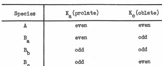
All asymmetric rotor eigenfunctions belong to one of the species of
the Group V. They may be correlated with the evenness or oddness of the
quantum numbers Ka and Kc in the limiting prolate and oblate rotors, as
shown in Table II below.
Table II. Classification of Asymmetric Rotor Levels.
Species K (prolate)
a Kc(oblate)
A even even
B even odd
a
a,,
odd odd [image:14.618.127.523.264.413.2] [image:14.618.179.504.581.713.2]The orientation of the permanent electric dipole moment with respect
to the principal axes determines between which levels transitions may
oc-cur. The matrix elements of the transition will be zero unless the
pro-duct of the characters for the initial and final wave functions and the
component of the dipole moment be ~ 1 for each of the group operations.
The components of the dipole moment along the axes a, b, and c belong
re-spectively to the species Ba, ~' and Bcof the Group
v.
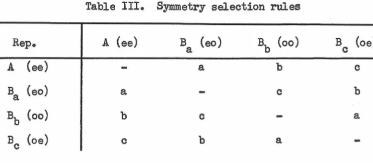
Table III gives the direction of the electric moment permitting transitions between statesbelonging to the various representations of the Group
v.
Rep.
A (ee)
Ba (eo)
Bb (oo)
Bc (oe)
Table III. Symmetry selection rules
A (ee)
a
b
c
B (eo)
a
a
c
b
Bb (oo)
b
c
a
5. SELECTION RULES FOR J, K, AND M.
B (oe)
c
c
b
a
The electric moment of a diatomic molecule is directed along the
line joining the two atoms. If M is the constant dipole moment, the
0
three components along the space fixed axes X, Y, Z are: M x
=
M0 sin 8 sin </> , and Mz
=
M0 cos 9 • The matrix elements of the dipole moment for the transition J1M1 -+ J"M" areaccordingly
RxJ'
,M'
;J" ,M" - M0
J
'f'
[image:15.615.145.521.305.469.2]J I M1 ·J" M"
R y ' ' ' M
I
JI M'*
0
\.f-"
'
sin 9 sin <:/>J"
,M"
rl.Y-.t
sin 8 d 9 d 'I',. J I M ' • Jlt M"
R z ' ' ' M
f
'f'
J''
M'*
cose
0
"I-'
J" ,M" sin 9 d 6 d </> •
The integrals involving <P vanish unless M11 - M1 for Rz and M" M'
:t 1 for
Bx
orRy•
This leads to the selection rule.6 M
=
o,
1: 1 •The integrals involving 8 can be shown to vanish except when J"
J'
±
1; therefore~J=
:t
1 .Similar considerations for the more complicated case of a symmetric
top yield the result that for an accidentally symmetric top the selection '
rules are
o,
:±
l ; ~ Ko,
+
-
1 ; .A M :. O, T l •The quantum number K has lost its significance in asymmetric tops.
However, transitions for which .6 K (prolate), AK (oblate), or both are
greater than
+
1 generally occur with reduced intensities. Theselec-tion rules
A J
=-
o,
±
1 ; AM -o,
±
1still hold as in symmetric tops.
6,, THE NON-RIGID ROTOR:
Molecules are capable of executing vibrations which, al though not
strictly a simple harmonic motion, are to a good approximation simple
har-monic vibrations. A generally satisfactory description which takes
ac-count of the slight deviation from harmonicity is the Morse function (9)
U (r) :. D { 1 - exp (-a (r - re) ) } 2 •
(6-1)
If the wave equation for the diatomic rotor is solved with the Morse
function for the potential energy the following expression for the term
values is obtained.
(6-2)
- D
.f
(J+
1)2 -o<
(v+
t)J(J+
1)+
• • • • •
e e
in which some higher terms have been neglected. The vibrational quantum
number, v, may take all positive integral values including zero. The first
two terms of
(6-2)
are the vibrational term value for a harmonicoscilla-tor and the anharmonic correction term. We shall not be concerned with
these in the pure rotation spectra. The remaining three terms represent
respectively the rotation of a non-rigid rotor at the equilibrium distance,
the correction for centrifugal distortion of the rotor, and the
correc-tion for the interaction of rotation and vibration. D can be shown to e
be 4B .3
/J,
where w is the energy of the vibration expressed in cm-1 • It eis generally so sma11 that its effect on the energy levels is nearly
neg-ligible. We may rewrite
(6-2)
asE/hc
=
F(J)=
BVJ(J+
1)where 0( e(v
+
i) ,
(6-4)and the terms involving only vibration have been dropped.
Bv represents an average value of the reciprocal moment of inertia
over a complete vibration. Even for a harmonic vibration the mean value
2 2
Actually, 1/r2 is slightly greater than l/re2• In addition, if the
vibration is anharmonic, we must expect
Bv
to be slightly smaller thanBe' since the average nuclear separation will be greater. In actual
physical cases the anharmonic term is greater than the harmonic one.
In a symmetric or asymmetric rotor we exp~ct the following
re-la tions to hold to a first approximation:
A(v) : A
2=
O('. A(v.+
d1./2) ,
e i 1 i
B(vl
=
Be
Lt</<v
1 T d/2),c[v}
=
c
eL.
i°' .
1c (
v. 1+
d1. /2) 'where we have lumped together the effect of the different vibrations, each
of degeneracy di' and let (v] stand for the value of all vibrational
quantum numbers.
In a non-rigid symmetric top there are terms due to the individual
effect on the B values of centrifugal stretching caused by rotation about
the axis of intermediate moment and about the figure axis. Slawsky and
Dennison (10) have given the following equation for the energy levels:
F(J,K)
B J(J+
1)v
+
(6-5)
Strictly speaking, equation
(6-5)
only represents the energy levels of asymmetric top when it is in a non-degenerate vibrational state. For a
molecule vibrating in one mode of a degenerate vibration, the rotation
to excite the other component or the vibration. This results in a net
vibrational angular mmentum about the symmetry axis of the top. Since
the vibrational angular momentum may add to the molecular angular
momen-tum in either a parallel or anti-parallel way, equation
(6-5)
must bemodified to include such a term.
F(J,K,
?
)
=
F(J,K) + 2~ ~ K -1 ~ ~ ~ 1 (6-6)For the pure rotation spectrum A~
=
O.For symmetric top molecules the magnitude of the energy shifts in
consequence of the centrifugal distortions due to non-rigidity depends
upon J and~ as well as the force constants of the molecule., E. B.
Wilson, Jr. (11) has devised a method of introducing this dependence into
the secular equation for the energy levels. For all but the simplest
molecules this method requires more knowledge than is usually available.
In general, a correction for centrifugal distortion will not be necessary
except in very light rotors for which the velocity of rotation is high,
or, in the case of heavier molecules, for very high values of J.
From equations (6-3) and (6-5) and the selection rules ~ J
=
+
1,~ K
=
o,
we predict transitions from J' --+ J at the followingfre-quencies:
V (me)
=
2B(v]JIJ)r
(linear molecules).11 (me)
=
2B[v]J - 2DJKJI? -4Di?
(symmetric tops).Typical values of Bv which give spectra in the easily accessible microwave
regions range from 2,000 to 15,000 me. DJ and DJK usually have values of
only a few kilocycles.
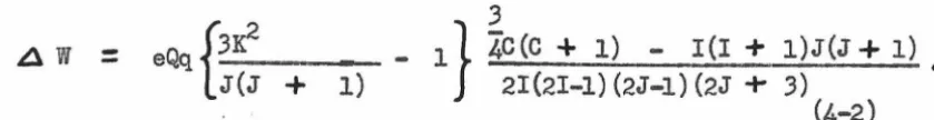
7, ELECTRIC QUADRUPOLE EFFECTS.
angular momentum
rli.
At low values of electric field strength thenu-clear and rotational angular momenta add together in the following way
to give the total angular momentum, F. F :: J
+
I, J+
I - 1,J
+
I - 2, •••I
J - II.
Different values of Fare associated withdifferent orientations of the nuclear spin with respect to the rotational
angular momentum of the molecule; therefore, different average values of
the interaction energy arising from the electric quadrupole moment
pos-sessed by the nucleus and the gradient of the electric field along the
internuclear axis of the molecule occur. Casimir (12) has treated the
shift of the energy levels as a perturbation problem; for a molecule
with one quadrupolar nucleus and with a symmetry axis he obtains
.6 V
=
-eQ /d
2v\ 2,Xc(c
+
1) - I(I+
;!Jir(J+
1) , (7-1)\ c) z2/ 4 2IJ(2I - 1) (2J - 1)
J
where the various quantities are defined as follows:
Q represents the departure of the nuclear charge from spherical
symmetry and is called the quadrupole moment.
~~~is
the second derivative of the potential due toelec-J
trons and other nuclei, taken along the space fixed Z axis, averaged over
the rotational state J, and evaluated at the quadrupolar nucleus.
C : F(F
+
1) I(I+
1) J(J+
1).The entire term eQ
La
2v)may be regarded as a\a
z
2 J .the splitting or an energy level. It varies from a fraction of a
mega-cycle to several hundred megamega-cycles according to the quadrupole moment
or the nucleus and the particular electronic and nuclear configuration
in the molecule. The spectral frequencies or absorptions are computed
by applying the selection rule AF
obtained from equation
(7-1).
--
o,
+ 1 to the energy levelsThis treatment is based on the assumption that only elements or the
perturbation matrix are important that are diagonal in J. This is a .first
order treatment. If the hyperfine splittings are not small compired with
the separation of the unperturbed levels, then second order correction
terms must be computed, using the perturbation theory.
Townes and Dailey
(13)
have presented an argument that only the pelectrons in the bonds adjacent to the quadrupolar nucleus are important
contributors to/
O
2V).
This appears to be a useful concept leading to\-a
z
2qualitative conclusions about the nature of the chemical bonding
(14)
inmolecules for which the hyper.fine structure can be resolved •
.§.& THE STARK EFFECT.
A. Linear Molecµles.
In the presence of an electric field along the space fixed Z axis
the energy levels of a linear molecule are shifted, and the degeneracy
between states with different values of the quantum number M is removed.
The perturbation operator is - .)-<Ecos 9 , withµ the permanent dipole
moment directed along the molecule fixed z axis, E the electric field,
and
8
the angle between the two axes. The perturbation operator is aaccount; instead, the problem may be solved by the usual first order
treatment for each value of M. The first order correction to the energy
is given by
w
(1)
JM
J
Ll.J ~ ll.J (8-1)
T JM ( - )-A E cos 8 ) T JM sin (J d 8 d
1' •
The properties of the associated Legendre functions which appear in the
'f'
JM require the integral to vanish.Second order perturbation theory (15) gives for WJM.(2)
w
(2)=
L If
~M•
(-fAE cos 9 )If'
J'M sin 6dB df>l
2JM JI -:/; J •
(8-2)
If the electric field is parallel to the electric vector of the microwave
radiation the quantum number M does not change.
Ll '21
J-+ J
+
13?1(16/
+
32J+
10) - 8J(J+
1)2(J+
2) µ 2E2- J(J
+
2)(2J - 1)(2J+
1)(2J+
3)(2J+
5) h2J10 •(8-3)
If )A E, the product of dipole moment and electric field, and "ll0 , the
unperturbed frequency, are known in megacycles, then ~1J , the shift in
frequency of the spectral line, will also be given in me. The conversion
factor from the usual units is: µ E (me)
=
•
5032 ,}A E (Debye uni ts)(volts/cm).
B. Symmetric Top Molecules.
Symmetric top molecules possess a dipole moment directed along the
unique symmetry axis. The perturbation operator is again - ,,(A Ecos 9 ,
and on account of the form of the symmetric top wave functions it is a
matrix diagonal in K and M. Therefore, the degeneracy of the energy
perturbation theory (15) has yielded the result
w
JKM
(1)
-
(p
E) KM/J(J+
1)Coles (3) has given the result of the second order calculation.
(8-4)
w
JKM(2) E2
.f:
2{lJ(J
r
3Jc2
+
1)-
lJ
[
J(J
3rt-
+
1)-
1
]
_r.f-i{-
J
8-S)2B · (2J - 1)(2J
+
3) .J3(J
+
1)3 •Levels with K or M equal to zero have no first order Stark effect.
C. Asymmetric top molecule§,
A perturbation operator is defined in the following way.
E is the electric field along the spa.ce fixed Z axis; g refers to the
molecule fixed inertial axes, x, y, z; µg are components of the dipole
moment along the principa.l axes;
~
Z are the direction cosines betweeng .
space fixed Z axis and molecule fixed inertial axes.
In the non-degenerate case, the wave functions of the asymmetric
rotor belong to the representations of the Group
v.
The direction cosinesbelong to the representation Bx' BY' Bz for g : x, y, and z
respective-ly. Non-vanishing matrix elements are obtained only if the product of
the direction cosine and the wave functions for the connected states
be-longs to representation A. Consequently, therece.n be no first order
Stark effect unless there is accidental degeneracy between two or more
levels.
=
[(~
Zg)J 1" M;J• '1''!llJ
2
0 0 '
W J 'f' - lJll JI '( I
w
J '1' M (2)
JI 'f' I g
) )
where the prime on the summation indicates that it extends only over
those values of J1 'T" 1 for which
w
0 J '1' is not nearw
0 J' '1'1 • Values
of (
~
Zg) may be obtained f'rom Tables of Line Strengths, published byCross, Hainer, and King
(16).
If accidental degeneracy occurs, then the perturbation trea,tment will
result in a simple second degree secular equation to be solved. Golden
and Wilson
(17)
have examined the possible cases of degeneracy and giventhe form of the Stark shifts. For degeneracy between states of the same
J (limiting symmetric rotor degeneracy) they find
AV
+
FIMIE • MBetween states of different J
~VM
=
± {
GVii -
pf-
}E 'where F and G are coefficients independent of M, J1 is the larger of the
th
J's involved, ~ VM is the shift in the frequency of the M Stark
com-ponent from the unperturbed frequency, and E is the electric field.
Stark splittings for the electric fields applied in microwave
spec-troscopy are usually less than 100 megacycles •
.2...
TliE ZEEMAN EFFECT.There are at least three sources of permanent magnetic moments in
molecules. A large magnetic moment of one or two Bohr magnetons may
arise in a small number of stable gaseous compounds and in free radicals,
due to the presence of unpaired electrons. Moments measured in nuclear
arise from the presence of nuclei with intrinsic magnetic moments.
UsU9.lly all electron spins are paired and the nuclear spins are
coupled to the rotation of the molecule. For a single spinning nucleus
we describe the molecule by the quantum numbers JIFM. The application
of a weak magnetic field leads to the total Hamiltonian given by c. K.
Jen (18).
_. _.a.
I • H ,
where gmole is the gyromagnetic ratio or the molecule along J, gN is the
...
g-ractor of the nucleus,
,,,u.
0 is the nuclear magneton, J, I are vectoroperators or J and I, and H is the external magnetic field. The
simil-arity to Russell-3aunders coupling in atomic spectra permits us to take
over the applicable equations and write for the interaction energy
w
=
-M ,.,,Uo H { o(. J gmole+
o(I gN} ' (9-1)where O<J F(F
+
1)
+
J(J+
1) - I(I+
1) /2F(F+
1)'
<XI=
F(F + 1)+
I(I...
1) - J(J -t l) /2F(F+
1) •It is usually most convenient to apply the external field pg.ra.llel to the
E-vector of the r~diation. This leads to o--tra.nsitions for which the
selection rule ~ M
=
+ 1 holds.There are three different possible situations. These are:
(1)
g mo 1 e
<<
gN (2) gN<<.
g mo e 1 (3) gN ~ g 1 mo e • The first twocases lead to a symmetrical splitting or a simple doubling of the
rotation-al levels. Quantitative measurements of the splitting yield vrotation-alues for
the g-factors • . Only a few substances have been examined; for
~
5H
3
arepresentative splitting is about 1.2 me for a field of 1700 oersteds.
gmole is known, it is possible to calculate the unknown g-factor.
·The preceding equations hold only for fields which perturb the lines
by an amount which is small compared to the original separation of the
hyperfine components. Higher fields begin to uncouple the spin from the
rotation of the molecule, and this leads to a Paschen-Back effect between
2000 and 10,000 oersteds in molecules with small ( 1 me ) quadrupole
coup-ling.
10. LINE SHAPF.8 AND INTENSITIES.
A. Line Shapes,
A truly isolated molecular system would possess definite and fixed
energy levels, but certain unavoidable disturbances perturb the energy
levels, giving a width to the spectral lines and varying their center
fre-queneies. These are:
(1) Natural line width
(2) Doppler effect
(3) Pressure broadening
(4)
Collisions with the walls(5) Saturation broadening
Spontaneous emission is responsible for the natural width of
spec-tral lines. Transition probability is proportional to the cube of the
frequency, which, in the case of rotational transitions, is so low that
the natural width of the lines is of the order of 10-7 cycles/sec.
Ir
a molecule is moving with a component of velocity parallel to theshift of 1- ( V ) v/vp occurs, where V is the resonant frequency at
rest, v the molecular velocity, and v the phase velocity of the radiation. p
Usually vp ~ c, the velocity of light in free space, and the fractional
frequency shifts are simply v/c. The velocity distribution in gases is
such that a symmetrical line with half width at half maximum of .6 V :::::
~
\/<2 k T loge 2)/m is obtained. For~
at 300° K. this amounts toc
70 kilocycles. Doppler broadening is smaller for heavier molecules and
can be decreased by lowering the temperature. It is important because
it may sometimes be the limiting factor in line width, and widths
ob-served to be in excess of the Doppler width may indicate removal of
de-generacies in the energy levels.
Van Vleck and Weisskopf (19) have derived an expression for the
shape factor of a microwave absorption line due to collisions of the
.
molecules with one another.
1
(10-1)
i2)
'
where Vo is the resonant frequency and 7' is the average time between
collisions for a molecule.
At atmospheric pressure the absorption lines can become several
thousand megacycles wide. Accurate frequency measurements are impossible
under these conditions; consequently, pressures below 1 mm of Hg are
com-monly employed. At these low pressures the time between collisions
be-comes large compared to the rotational frequency; then the second term in
F( V, V0 ) All
~---
.
(10-2)
( 11 - Vo )2 + ~v2The line half width, All, which is proportional to the number of
col-lisions per second, is directly proportional to the gas pressure at a
fixed temperature. A very rough value of AV for many gases is 15
me/sec for a gas pressure of 1 mm of Hg. At pressures below 10 -2 mm
of Hg the pressure broadening becomes less than the Doppler broadening.
Collisions with the walls introduce a small but not negligible
width to absorption lines. For NH
3 in K band waveguide (l cm by 0.5 cm)
at room temperature, the resulting half width is only 7 kilocycles.
If energy of sui'fieient intensity is absorbed by a gas, the molecules
may be promoted from the lower state to the_ upper state more rapidly
than they can be returned to the lower state by collisions. A
conse-quent drop in the absorption must be expected. Such saturation occurs
first at the resonant frequency since the absorption is highest at this
frequency. The center of the line is depressed and the. line appears
broadened. Since the relaxation time incr.eases at lower pressures,
satu-ration effects set in at lower power levels as .the pressure is reduced.
At lo-2 mm of Hg, saturation can be avoided by keeping the radiation flux
below about l milliwatt per square cm.
B. Line Intensities.
If the microwave power is kept low, the following law of absorption
is valid.
I
=
I exp(-Y" x) •0
(10-3)
I is the intensity of the incident wave at a particular frequency, I is
the intensity of the transmitted wave, and Y' is a constant called the
absorption coefficient, which is a function of the frequency.
If one neglects the 2I + 1 degeneracy in the nuclear statistical
weight factors, which is equivalent to the assumption that the hyperfine
structure is not resolved, the following equation gives the absorption
coefficient at the resonant frequency for a single Stark component of a
microwave transition.
N
=
number of molecules per cc in absorbing path.11
=
frequency of rotational line in cycles/sec.(10-4)
F
vSrgJ
exp{-Wr) I~ kT~g· component of the dipole moment along the principal axes a, b,
and c.
2
I (
P
Fg) J .,. M;J, 'I' 'MI •
squared matrix elemnt of the direction cosines between space fixed axes F • X, Y, Z and moleculefixed axes g • a, b, c.
AV = half width of line at half maximum points.
c,k,T
=
velocity of light, Boltzmann constant, and absolutetem-peratureo
F v
=
~{
exp(-Wv/kT} /~
=
fraction of molecules in the particularvibrational state observed. Wv is the energy above the ground
state, and Q is the vibrational partition function. v
gigJ{exp(-W/kT)} / Qr
=
fraction of molecules in the lowerrotational state of the transition. gigJ is the statistical
The total absorption coefficient of the transition in the absence
of a field is often desired. This quantity is obtained by summing the
squared matrix elements over all M values from -J to
+
J. The threedi-rections
x,
Y, and Z are equivalent in the absence of an external field,hence the summation over x, Y, Z in (10-4) may be replaced by the factor
Two very important conclusions can be drawn from equation (10-4).
2
Since Y is proportional to V , the intensity of absorption lines will
increase rapidly for transitions between higher and higher J values.
However, this advantage is partly offset by the difficulty of obtaining sufficient microwave power at these frequencies.
If the pressure is so adjusted that the line width is determined
by pressure broadening, r is independent of pressure, since both N and
AV are directly proportional to pressure. In order to obtain the
narrowest lines without sacrificing intensity, one should pump out the
cell just to the point where the line width is determined by the Doppler
effect and reduce the temperature as far as possible without condensing
II. DISCUSSION OF ERRORS IN MICROWAVE STRUCTURE DETERMINATIONS.
Several factors limit the ultimate accuracy of molecular structure parameters computed from microwave data.
(1) Uncertainty in Planck's constant. (2) Uncertainty in atomic weights.
(3) Uncertainty in measured frequencies.
(4)
Zero point vibrations.A recent adjustment of the atomic constants (20) has yielded a value of (6.623773 :t: .000180) x lo-27 erg sec for Planck's constant. Any error from, this source will not affect the structure parameters in a significant way.
Most atomic weights for the more common elements have been measured to one part in 105, but a small number are known only to one part in 104• The difference in the weights of various pairs of isotopes may be uncer-tain by 0.1 percent. Measurements of the frequency shift of a rotational line when one isotope is substituted for another may likewise be in error by 0.1 percent. In unfavorable cases these sources of error may intro-duce an uncertainty of 0.1 percent into the structure parameters.
A much more serious error is introduced by the zero point vibrations of molecular systems. Microwave measurements of the rotational constants for molecules in the ground state yield B0 rather than the equilibrium value, Be' where
B
In general, not all of the
o<.
are known; consequently, the equilibrium1
distances, r
r0, the average distance the atoms would have to be separated in order
to give the observed values of B
0• Unfortunately, ma.king an isotopic
substitution changes the
o<.B
at the same time. so that the new B does1 , 0
not correspond to the original average configuration of atoms but
rep-resents a very slightly changed average configuration.
In any molecule with a figure axis, if an atom of mass m on the
axis is replaced by an isotope of mass m', then the distance of these
atoms from the center of mass of the original molecule is given by
z 12 :: (I 1 - I )(M
+
.6 m)/M Ll m •0 0 0
(l-1)
This equation is derived for a vibrating molecule in Appendix I. One or
the other of the quantities I0' and I
0 may be regarded as being in error
by the amount Ll I0 due to neglect of the change in zero point vibration
amplitude. The error introduced in z
0' is given by
6 z ' 0 (1-2)
obtained by differentiating the expression for z0' with respect to I
0' .
The error is largest for atoms which are located nearest the center of
mass.
It is possible to solve for the bond distances directly if enough
measurements of 10 have been made. The bond distances of the linear
mol-ecule OCS have been calculated (21) for several isotopic pairs. Serious
lack of agreement between the different values obtained from different
pairs indicates that before putting too much faith in the results of such
calculations one should investigate them carefully. For this particularly
simple molecule it is possible to write the following expressions for the
For the pair
ocs
-
ocs• only:2
{ (M
+
~ m)I ' mMr
0
J
/m
0m
0(1 ms•
roe
=
0 SI-
_ ) .ms
ms
(1-3)
For the pair OCS
-
o•cs
only:2
{ (M
+
L1 m) I 1 m 'Mlo} /msmc (1 mo') •
rsc
=
0m;-
0-mo (1-4)
Due to neglect of zero point errors, one or the other of the quantities
I
0
1 and I
0 is in error by
Ll roe
=
.A I0• Differentiation with respect to I
0 gives
ll I
0 (M
+
A m)/2r00m011lc
(l ms') ms , (1-5)m A I
0 (M
+
A m)/2r08m
8mc (1 -m:')
•
(1-6)An examination of equations (1-5) and (l-6) shows that for a ratio of
iso-topic masses m 1/m or m 1/m
0 approaching unity, the bond distance becomes
s s 0
catastrophically sensitive to errors in measurement of I • Even for ratios
0
of 34/32 or 18/16 it is easy to see that rather poor values for r
00 and
res are likely to be obtained if the change in ()(:upon isotopic
sub-stitution shifts the absorption line as much as one megacycle. In this
way, an error of one part in 20,000 in a moment of inertia measurement
may show up as nearly a one percent error in a bond distance.
For molecules which are too complicated to analyze in this way, the
application of equation (l-1) has much to recommend it. Even an
under-determined molecule, one for which there are fewer moment of inertia
measurements than structural parameters,
may
permit calculation of someof the bond distances. A just determined molecule may be solved for some
of the distances by equation (1-1), and the simultaneous equations for
selecting a highly sensitive method (with respect to multiplication of
errors) of solving the simultaneous equations is greatly reduced.
Fin-ally, an overdetermined molecule may be solved completely without the
necessity of solving simultaneous equations.
No method of calculation is capable of yielding accurate bond
dis-tances for atoms which are very near the center of mass, since their
,llI. DESIGN, CONSTRUCTION, A.ND OPERATION OF T"tlE MICROWAVE SPECTROSCOPE.
A microwave spectroscope is a device for detecting absorption of
energy in the 1 mm to 2 cm region of the spectrum and for measuring the
frequency of the absorption. The absorbing material is generally a gas,
maintained at a low pressure and exposed to microwave radiation in an
absorption cell capable of transmitting microwaves. The frequency of the
monochromatic source is swept repeatedly through a small region of the
spectrum in a linear way. Absorptions are displayed as deflections on
a synchronized cathode ray oscilloscope trace.
In order to be suitable for the most general applications, a
micro-wave spectroscope must possess the following qualities: high sensitivity,
freedom from spurious responses, and ability to search smoothly over a
large frequency range. It is the task of the designer to produce an
in-strument in which all of these qualities are compatible.
There are three f'undamentally different designs: the
superhetero-dyne, the crystal video, and the Stark modulated microwave spectroscope.
The superheterodyne is extremely sensitive, but it is excessively
compli-cated for use as a s~rch instrument. The crystal video instrument is
recommended only by its simplicity, since the sensitivity is limited by
the low power handling capability, and, in addition, difficulties with
spurious responses and tuning problems are almost overwhelming. Stark
modulation eliminates most of the shortcomings of the other two systems,
but it alters the shape of the absorption lines and introduces troubles
with electrical pickup.
1. The Complete In§trumen!&
The instrument is a 50 kc Stark modulated spectroscope employing lock-in
detection and either oscilloscope or recording meter presentation.
Ap-proximate frequency measurements are made with cavity wavemeters, and
precise measurements are made by comparing the unknown absorption with
the ammonia spectrum, using a crystal controlled secondary frequency
stan-dard. All units of the equipment except the oscilloscopes, radio
re-ceiver, klystron, and certain waveguide components were designed and
con-structed in this laboratory. Several striking metamorphoses occurred
during the construction of the instrument, eventually leading to its
present form.
~-Generation and Propagation of Microwaves.
Microwave energy is generated by a reflex klystron oscillator,
the Western Electric 2K-50, which can be varied in frequency over a range
of about 4000 me about a center frequency of 23 kilomegacycles. The
bend-ing of a bimetallic strip flexes the resonant cavity and controls the
frequency. This thermal element is heated by the plate current in a
triode section of the 2K-50. Grid voltage for this triode is taken from
a ten turn helipot which may be adjusted manually or driven slowly through
the entire spectrum by a synchronous motor at a rate of 40 me per minute.
The beam voltage of the klystron is regulated electronically, and the
re-flector electrode and triode grid voltages are supplied from batteries.
A circuit diagram is given in Fig. 2.
A series of high voltage, mechanically tuned, reflex klystrons
man-ufactured by Raytheon Electronic Co. are on hand for use in investigations
tubes, the QK-289, 2K-33, QK-142, QK-226, QK-227, and QK-.306 cover a
region of the spectrum from 17 to .30 kilomegacycles, and a second region
from .36 to 50 kilomegacycles.
An
electronically regulated, high voltagepower supply was constructed in order to operate this series of tubes.
Figure 3 is a schematic circuit diagram of this power supply.
Microwaves are propagated along the one centimeter rectangular
wave-guide in a transverse electric mode, the TE
01•
An
attenuator (0-10 db)isolates the klystron and prevents reflections from discontinuities in
the wave guide from disturbing the frequency of the klystron. No attempt
is made to eliminate the standing waves set up by these discontinuities.
Approximately one percent of the microwave energy is abstracted by
a 20 db directional coupler and diverted into the wavemeters and the
bar-monic frequency standard. The rest of the energy passes through a tapered
horn into a standard ammonia cell (to be described later) and then into
the main absorption cell.
3. Absorption Cell.
The absorption cell consists of a twelve foot length of three
cen-timeter copper waveguide whose ends are sealed with thin (.010 inch) mica
windows held in place by a hard wax. The cell is connected through a
stopcock to a hj.gh vacuum system and can be evacuated to an estimated
pressure of
io-
6 mm. An R. C, A, thermocouple gauge on the absorptioncell side of the stopcock permits a continuous approximate measurement
of the sample pressure. This is very important, since large adsorption
effects are often observed with the gaseous samples employed in microwave
Provision is made for the introduction of an electric field
pir-allel to the electric vector of the microwave radiation inside of the
absorption cell. A 1/1611 x 3/4" steel bus bar is supported in the exact
center of the cell by slotted te!'lon strips and extends the entire length
of the cell. A flexible electrical connection is made to this electrode
through a glass to kovar seal. Considerable relative movement of
elec-trode and cell must be expected due to exp:l.nsion and contraction with
changes of temperature. A cross section of the absorption cell is shown
in Figure
4.
4.
Mechanism of Stark Modulation!.Modulation of the absorption lines by the Stark effect was first
introduced by Hughes and Wilson (22). If we imagine the source
oscilla-tor tuned to a fixed frequency and the position of the absorption line
moved back and forth by a varying electric field, it is easy to see that
amplitude modulation can be produced. Now, if the line is moved back and
forth by a radiofrequency square voltage waveform impressed on the
elec-trode and the klystron is swept over the absorption line at a rate which
is slow compared to the molecular modulation, the absorption lines can
be displayed on an oscilloscope by amplifying the modulation frequency,
detecting it, and applying the absorption line envelope to the vertical
deflection plates of the oscilloscope. The spot is swept horizontally
across the face of the cathode ray tube by the same sawtooth waveform of
voltage that is simultaneously sweeping the klystron over the absorption
line. This sawtooth voltage is actually generated in the oscilloscope
and is fed to the negatively charged reflector electrode of the klystron
The train of microwaves emerging from the absorption cell is
modu-lated by the square wave frequency which, in turn, is modumodu-lated by the
absorption line envelope. The microwaves are p:i.ssed through a tapered
reducing horn into a one centimeter section of waveguide provided with a
tuning stub and a movable shorting plunger. A probe extends into this
section and is connected to a lN-26 silicon crystal rectifier. In
prac-tice, the shorting plunger and tuning stub are adjusted to yield a
max-imum standing wave of voltage at the pickup probe. The crystal
recti-fier p:i.sses on only the square wave, modulated by the absorption line
envelope.
At this point one of the great advantages of Stark modulation
becomes app:i.rent. If some discontinuity in the waveguide introduces a
frequency sensitive variation in microwave power, this merely shows up
as a shift in the DC output level of the crystal. However, the modulated
absorption signal is unaffected except for a small change in its
ampli-tude. If no modulation were used, the change in power due to the
dis-continuity might completely mask the minute dip in power caused by
mol-ecular absorption.
j. The Modulation Waveform1
A square waveform was chosen for modulation purposes to avoid
smearing the absorption lines. The square waveform is electronically
clamped to a DC voltage which can be varied from zero to one thousand volts.
Since there are only two different values the electric field can assume,
modulation of the microwaves is introduced at only 2 (J of- 1) frequencies,
corresponding to the splitting of the line into its J
+
1 Starktwo different positions corresponding to the top and bottom of the square
wave. Had some other waveshape been employed, absorption would have
oc-curred at all intermediate frequencies, leading to a hopeless smearing of
the absorption line and its Stark components.
The modulation frequency is determined by three conflicting factors.
The first is the difficulty of developing a voltage waveform with high
frequency components across the low impedance presented by the .001
micro-farad capacity of the waveguide and Stark electrode. This consideration
dictates as low a modulation frequency as possible. The second factor
is the dependence of the noise temperature of the silicon crystal
rec-tifier upon frequency. A considerable amount of experimental data has
been obtained by Miller, Greenblatt, and others (23) at the University of
Pennsylvania which shows that the noise of a crystal rectifier is an
in-verse function of the frequency at power levels above a few microwatts.
Since the limiting sensitivity of the microwave spectroscope is deternUa.iied
by the overall noise figure, and since the crystal contributes more noise
than any of the other circuits, one would like to use as high a
modula-tion frequency as possible, in order to·reduce crystal noise to a minimtun.
The third factor is the effect of an uncertainty in the time on the energy
levels of the molecules. If the energy levels are periodically shifted
back and forth and remain in ea.ch state a time t
2:...,
where V isv
the repetition rate of the square wave, then to a first approximation the
energy levels will be broadened by an amount A E given by the equation
~E A t ~
1i..
Therefore, the line acquires a width h v • A rigorous calculation of
the dependence of line shape on 1) has been given by Karplus (24), using
time dependent perturbation theory. A modulation frequency of 50
kilo-cycles was finally chosen as a suitable compromise for all factors.
6. The Sguare Wave Generatou
Figures 5 and 6 represent schematic diagrams of the square wave
gen-erator and its power supply. The frequency is stabilized by a 100
kilo-cycle crystal oscillator which triggers a multivibrator every other kilo-cycle.
The resulting waveform is clipped and amplified before it is applied to
the grids of.two parallel-connected cathode followers. A square wave
with an amplitude of 350 volts and a rise time of about 1 microsecond is
obtained on the electrode in the absorption cell.
7. Prea.mplification,
Modulated signals from the crystal detector are fed directly into
the low noise preamplifier shown schematically in Figure 7. Rectified
microwaves pass through a 0 - 150 microammeter which serves to monitor
th.e power available from the klystron and also indicates whether the
standing wave ratio in the waveguide possesses a maximum at the crystal.
The 50 kc component corresponding to molecular absorption is isolated from
the meter by an inductance and is caj:acitively coupled into the primary
of a specially designed step-up transformer (1:15), which drives the grid
of a low Q tuned amplifier, followed by a resistance coupled stage of
amplification, The voltage gain of the combination is approximately 5 x
io4.
8, Final Detection.
A-heterodyne, or lock-in detector has been employed with marked
the circuit accrue from its narrow bandpl.ss and its ability to
differenti-ate between signals of opposite phase. Figure 8 shows the circuit diagram
for the lock-in detector and associated circuits. Signals from the
pre-amplifier are passed through one more tuned stage of amplification and are
impressed on the control grid of a pentode. The suppressor grid of this
pentode is modulated by a sine wave of sufficient amplitude to switch
the pentode on and off at the exact frequency of the signal on the
con-trol grid. BXact coincidence in frequency is obtained by generating the
sine wave from the same square wave which produces the modulation of the
microwaves. A phase shifter is necessary in order to compensate for the
different phase shifts which the two signals experience in pl.ssing through
their respective circuits. Probably the simplest way to think of the
operation of this